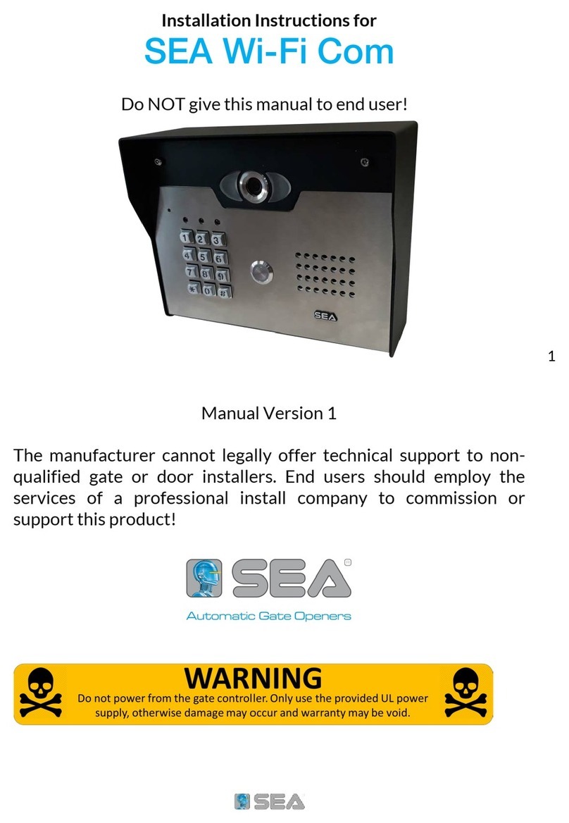
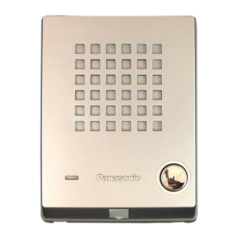
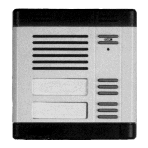
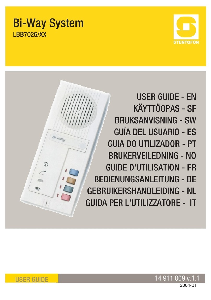
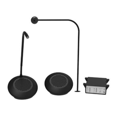
SEA KIT MIRO 6F AK User manual

Videokit anti-vandalo Mono-familiari e Bi-familiari
One Way, Two Way Vandal Resistant Videokit
Norme Tecniche
Owner’s Manual
We recommend
This equipment is installed by a
Competent Electrician, Security or
Communications Engineer.
Si raccomanda
di far installare il presente disposi-
tivo esclusivamente da personale
qualificato.
SEA S.p.A.
Zona industriale 64020 S.ATTO Teramo - (ITALY)
Tel. +39 0861 588341 r.a. Fax +39 0861 588344
www.seateam.com [email protected]
KIT MIRO 6F AK
R
Sistemi Elettronici
di Apertura Porte e Cancelli
International registered trademark n. 804888
Italiano
English
67411820 Rev.00 - 09/2014

2
Rev.00 - 09/201467411820
The KIT MIRO 6F AK is a new range of videokits that use the external door
station, vandal resistant modules (the speaker unit is a specific module while
the camera is a standard module) and the videophone which is specific for this
range of videokit and range.
As a result of using microprocessor technology in the door panel and video-
phone, a number of additional features have been added to enhance the opera-
tion of the videokits and give greater feedback to the visitor and user.
•Disability friendly, visual and acoustic signals from the door panel to inform the
visitor of call status (call made, ringing, speak, door open).
•Programmable door open and conversation time.
•Expandable to 4 entrance panels (requires an additional relay for each en-
trance panel).
•Connections for a push to exit button.
•Two methods of operating the electric lock:- 1) Dry contact relay, 2) capacitor
discharge circuit.
•Facility for the connection of other modules supplied by 12Vdc (300mA max).
•Programmable number of call tone rings from 2 to a maximum of 8.
•Input for local door bell push button.
•Programmable timed privacy function from 15 minutes to a maximum of 8
hours.
•Door open status LED (additional wire required from the door to the video-
phone)
•Up to 4 videophones can be connected in parallel, all with intercommunication
facility.
•Videophones can have a maximum of two additional audio telephone handsets
connected in parallel.
•Camera recall on all systems, with selective recall on systems with multiple
entrances.
•Door panel camera can be adjusted horizontally and vertically (10 degrees).
The kit comprises of.
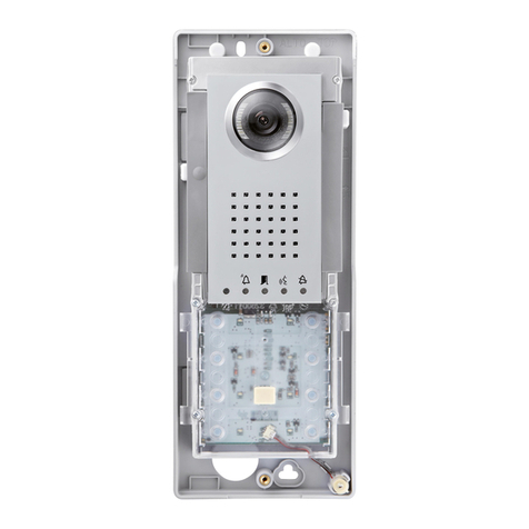
1 B&W Camera module from vandal resistant line. The unit includes a high
quality B&W CCD camera with auto iris lens, infrared LEDs for illumination
1 Specific speaker unit module which includes the audio amplifiers and one
call button;
1 Two module front support with flush mounting box (the surface version of the
kit includes the relevant surface mounting box);
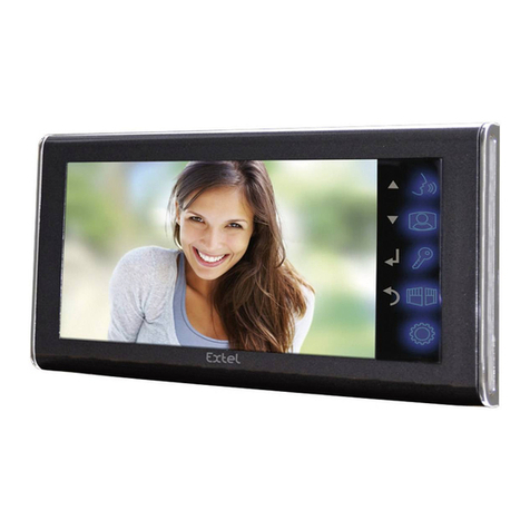
1 Videophone with 3.5” colour TFT flat monitor, “door open/intercommunicating
call”, “camera recall” and “Privacy on/Call reject/Service” push button plus
“on” and “door open” LEDs* and one “privacy on” LED. Electronic call tone
with 3 level adjustable volume. Controls: picture hue and brightness. Com-
plete with wall mount support.
1 Power transformer boxed in 5 Module A Type DIN BOX.
With 3 modules mounting box for flush version or for surface version plus vandal
resistant line stand-alone codelock module. The user can open the door from
outside by typing the relevant access code into the keypad.
As the one way version but with 2 videophones, 2 power supplies and vandal
resistant speaker unit module with 2 call push buttons.
I KIT MIRO 6F AK fanno parte di una nuova linea che utilizza i nuovi moduli (il
modulo portiere elettrico è specifico per il videokit mentre il modulo telecamera
è standard) antivandalo ed il videocitofono (colori).
Grazie all’impiego della tecnologia a microprocessore sia nel modulo portiere
elettrico che nel videocitofono, i kit di questa linea offrono numerose funzioni
innovative tra le quali troviamo:
•Segnalazioni acustiche e visive in merito al funzionamento del sistema in aiuto
degli utenti diversamente abili;
•Possibilità di utilizzo della serratura tramite relè a contatti puliti o scarica ca-
pacitiva;
• Possibilità di collegare un pulsante per l’apertura diretta della porta d’ingresso;
•Possibilità di programmazione dei tempi d’apertura porta e conversazione;
•Possibilità di collegare fino a 4 ingressi con l’ausilio di relè d’asservimento,
•Predisposizione per il collegamento di altri moduli alimentati a 12 volt;
•Possibilità di programmare il numero di squilli da un minimo di 2 ad un mas-
simo di 8;
•Ingresso per chiamata di piano-locale;
•Possibilità di monitorare lo stato d’apertura-chiusura della porta tramite apposi-
to LED presente sul videocitofono (è richiesto un conduttore addizionale dalla
porta verso il videocitofono);
•Possibilità di programmare la funzione privacy da un minimo di 15 minuti ad
un massimo di 8 ore;
•Predisposizione per il collegamento facilitato di un citofono in parallelo (max 2
indipendentemente dal numero di videocitofoni in parallelo);
•Possibilità di collegare fino a 4 videocitofoni in parallelo con funzione di inter-
comunicazione;
•Auto-accensione selettiva in caso di più ingressi;
•Brandeggio telecamera regolabile sia verticalmente che orizzontalmente con
un’escursione massima di 10º.
Il kit comprende:
1 Modulo telecamera colori della linea anti-vandalo che incorpora una teleca-
mera colori CCD autofocus di alta qualità e i LED d’illuminazione ad emis-
sione di luce bianca;
1 Modulo portiere elettrico della linea antivandalo che incorpora la circuiteria di
amplificazione audio e il portiere elettrico con un pulsante di chiamata;
1 Supporto da incasso ad 2 moduli (nella versione da superficie questo articolo
è rimpiazzato dalla relativa scatola da superficie);
1 Videocitofono a colori con monitor LCD TFT da 3.5”, pulsanti di “auto-accen-
sione”, “apri-porta/intercomunicazione” e “privacy/rifiuto chiamata/servizio”,
LED “monitor on”, “door open” e “privacy on” e chiamata tramite nota elet-
tronica con volume regolabile su 3 livelli. Controlli: saturazione e luminosità
immagine. Completo di supporto per l’installazione a parete;
1 Trasformatore di alimentazione (Cont. DIN 5 Moduli tipo A).
Con supporto a 3moduli nella versione da incasso o nella versione da superficie
più modulo tastiera digitale linea anti-vandalo. L’utente può aprire la porta digi-
tando l’apposito codice tramite la tastiera.
KIT MIRO 6F AK
Videokit Monofamiliare con videocitofono e telecamera colore
KIT MIRO 6F AK
One way videoki with colour videophone and camera
KIT MIRO 6F AK - KIT MIRO 6F AK-S
Videokit Monofamiliare colori più tastiera digitale
KIT MIRO 6F AK - KIT MIRO 6F AK-S
One way videokit colour plus a codelock module

3
Rev.00 - 09/201467411820
15,70
60,70
383,40
43,00
15,70
135,00
400,40
MARKINGMARCATURA
La marcatura CE di conformità indica che il prodotto soddisfa i requisiti del-
le Direttive della Comunità Economica Europea in vigore in particolare EMC
2004/108/ECC, LVD 2006/95/ECC e la CE-MARKING 93/68/ECC ad esso appli-
cabili. La marcatura CE, apposta sui prodotti dal fabbricante (o da un suo man-
datario) sotto la propria responsabilità, è stata creata con l’intento di eliminare
gli ostacoli alla circolazione dei prodotti all’interno degli Stati membri dell’Unione
Europea armonizzando diverse normative a carattere nazionale.
CE conformity marking indicates that the product respects the requirements
of the applicable European Community Directives in force specifically EMC
2004/108/ECC, LVD 2006/95/ECC e la CE-MARKING 93/68/ECC.
CE marking is applied by the manufacturer (or party delegated to do so by the
manufacturer) under their own responsibility. It was created to eliminate obsta-
cles to the circulation of products in European Union Member States by harmo-
nising different national standards.
KIT MIRO 6F AK KIT MIRO 6F AK-S

4
Rev.00 - 09/201467411820
VIDEOCITOFONO
Pulsanti, LED, Controlli, Impostazioni e Segnali
VIDEOPHONE
Push Buttons, LEDs, Controls, Settings & Signals
161
178
218
62
46
12
ON
SW2
6 7 8
1235
4
ON
SW1
Pulsanti Push Buttons
Pulsante di auto-accensione.
Sollevare la cornetta e premere il pulsante (una volta per il posto esterno 1,
due volte per il posto esterno 2 e così via fino a 4 ingressi): il relativo LED
si accende insieme al monitor che mostra il video proveniente dall’esterno.
La fonia verso l’esterno è attiva ed è possibile aprire la porta premendo il
pulsante chiave .
Camera recall button.
Pick up the handset then press the button (Press once for door/gate 1, twice
for 2 and so on up to a maximum of 4 entrances): the relevant LED switches
ON and the monitor switches on showing the video coming from the door
panel.
The speech lines are active and you can open the door by pressing the key
button
Pulsante apri-porta. Con la cornetta sollevata a seguito di una risposta o
a seguito di una auto-accensione, premere questo pulsante per aprire la
porta. Se il morsetto 14 del relativo LED è opportunamente collegato, il LED
resta acceso fino a quando resta accesa la porta.
Door open button. With the handset lifted and speech lines open to the en-
trance panel, press this button to open the door. If the terminal 14 is properly
connected the relevant LED remains switched ON until the door is closed.
Pulsante “privacy” ON-OFF / Servizio
•In stand-by, questo pulsante attiva (LED acceso)/disattiva (LED spento) la
funzione “privacy”, in ogni caso la funzione si disattiva automaticamente
allo scadere del tempo programmato. Con il servizio attivo il videocitofono
non riceve le chiamate.
•Durante la conversazione, premendo questo pulsante si attiva la relativa
uscita open collector sul morsetto “17”. L’uscita è attiva per 2 secondi ogni
volta che il pulsante viene premuto.
Privacy ON-OFF button / Service.
•When the system is in stand-by, the pressing of this button activates (LED
switched on) or disables (LED switched off) the “privacy” service. The ser-
vice is automatically disabled when the programmed privacy time expires.
When the service is enabled the videophone does not receive calls.
•During a conversation, the pressing of this button activates the relevant
output (open collector) on terminal “17”. The output is enabled for 2 sec-
onds each time the button is pressed.
LED LEDs
LED ON: è acceso quando il videocitofono è in funzione ON LED: switched ON when the videophone is operating
DOOR OPEN LED: può essere utilizzato per qualsiasi genere di segna-
lazione (di norma lo stato di apertura/chiusura della porta). Richiede una
connessione adeguata al tipo di segnalazione
DOOR OPEN LED: can be used to indicate the status of a door or gate. It
requires a switched 12Vdc connection to terminal 14.
PRIVACY ON/OFF LED:
•Quando il videocitofono è in stand-by segnala lo stato di attivazione (acce-
si) /disattivazione (spento) del servizio privacy;
•Quando il videocitofono è in funzione questo LED si accende per tutto il
tempo che il pulsante resta premuto.
PRIVACY ON/OFF LED:
•When the videophone is in stand-by, this LED signals the privacy service
status (ON = service enabled, OFF = service disabled) ;
•When the videophone is active, this LED indicates the activation of the
output on terminal 17.
Controlli Controls
Regolazione Volume nota dichiamata (3 Livelli) Call tone volume control (3 levels)
Regolazione Colore Hue control
Regolazione Luminosità Brightness control

5
Rev.00 - 09/201467411820
Impostazioni (Dip-Switch) Settings (Dip-Switches)
L’impostazione del videocitofono viene eseguita tramite i 2 dip-switch accessibili
dalla parte posteriore dello stesso.
The videophone setup is carried out by the 2 dip-switches accessible from the
rear of the videophone.
DIP-SWITCH a 8 VIE (SW1) 8 WAY DIP-SWITCH (SW1)
Switch 1 Indirizzo d’Appartamento
OFF 1
ON 2
Switch 1 Apartment Address
OFF 1
ON 2
Switch 2,3 Indirizzo Interno
OFF OFF 1
ON OFF 2
OFF ON 3
ON ON 4
Switches 2,3 Extension Address
OFF OFF 1
ON OFF 2
OFF ON 3
ON ON 4
Switch 4 Intercomunicazione
OFF tra i videocitofoni dei due appartamenti
ON tra i videocitofoni dello stesso appartamento
Switch 4 Intercommunication
OFF Between videophones of the two apartment
ON Between videophones in the same apartment
Switch 5,6 Numero di squilli
OFF OFF 2
ON OFF 4
OFF ON 6
ON ON 8
Switches 5,6 Number of Rings
OFF OFF 2
ON OFF 4
OFF ON 6
ON ON 8
Switch 7,8 Durata Privacy
OFF OFF 15 minuti
ON OFF 1 ora
OFF ON 4 ore
ON ON 8 ore
Switches 7,8 Privacy duration time
OFF OFF 15 minutes
ON OFF 1 hours
OFF ON 4 hours
ON ON 8 hours
DIP-SWITCH a 2 VIE (SW2) 2 WAY DIP-SWITCH (SW2)
Il dip-switch a 2 vie serve per adattare l’impedenza del segnale
video. L’impostazione di default è “ON” per entrambi gli switch
(75 Ohm): in presenza di più videocitofoni collegati in parallelo
(senza distributore video), gli switch devono rimanere entrambi
ad “ON” solo per l’ultimo (in ordine di connessione) videocito-
fono, mentre per tutti gli altri devono essere impostati entrambi
ad “OFF”.
The two way dip-switch adjusts the impedance of video signal.
The default setting is “ON” for both switches (75 Ohm): when
there are more videophones in parallel connection (without
video distributor) both switches must be “ON” only on the last
videophone (looking at the connection order) while for all other
videophones both switches must be set to “OFF”.
Compatibilità Compatibility
Per quanto concerne il funzionamento standard, è perfettamente compatibile
con i corrispondenti modelli KIT MIRO. I morsetti di collegamento corrispondono
esattamente in base al numero fatta eccezione per i morsetti che si riferiscono
ai pulsanti di servizio o ai LED che in base al modello di videocitofono possono
essere presenti o memp.
The videophone is fully compatible with the KIT MIRO. All primary connections
are the same but spare buttons and LED connections are different depending on
the availability of these services on that model of videophone.
Segnali sulla scheda di connessione Signals on connection board
Uscita fonia proveniente dal microfono della cornetta e segnale dati (12V
circa in stand-by, 5V circa in conversazione) 1Speech line output from handset’s microphone and data signal (About 12V
in stand-by, about 5V in conversation)
Ingresso fonia verso l’altoparlante della cornetta (12V circa in stand-by, 3V
circa in conversazione) 2Speech line input toward the handset’s loudspeaker (About 12V in stand-by,
about 3V in conversation)
Ingresso fonia verso l’altoparlante del citofono collegato in parallelo (12V
circa in stand-by e 3V circa in conversazione) 3Speech line input toward the loudspeaker of the parallel telephone (About
12V in stand-by, about 3V in conversation)
Segnale video bilanciato 1 sinc.- 4Balanced video signal 1 sync.-
Segnale video bilanciato 2 sinc.+ 5Balanced video signal 2 sync.+
Ingresso d’alimentazione – riferimento di massa 6Ground
7
Ingresso/Uscita 20Vdc (come ingresso 16÷20Vdc 0,5A – come uscita 20Vdc
0,5A max) 820Vdc Input/Output (As input 16÷20Vdc 0,5A – as output 20Vdc 0,5A max)
Ingresso d’alimentazione 24Vac 1A max 924Vac 1A max power input
Ingresso d’alimentazione 0Vac 10 0Vac power input
Uscita riferimento di massa citofono in parallelo 11 Output ground for parallel telephone
Uscita tono di chiamata per citofono in parallelo 12 Output call tone for parallel telephone
Ingresso comando apri-porta citofono in parallelo 13 Input for door-open command from parallel telephone
Ingresso 12Vdc per LED di segnalazione porta aperta 14 12Vdc input for door-open LED
Ingresso per chiamata locale (5V stand by, 0V in funzione) 15 Local call input (5V in standby, 0V to trigger)
16
Uscita pulsante di servizio di tipo attivo basso abilitata dalla pressione del
pulsante 17 Service button (open collector) active low output. The button goes active
when the button is pressed during a conversation

6
Rev.00 - 09/201467411820
135cm
a
a
a
b
c
c
f
ff
f
g
e
d
bb
b
a
A
B
h
il
m
m
m
m
cn
Fig.1 Fig.2
Fig.3 Fig.4
•Dovendo passare attraverso la fessura “e” (fig.2A) della placca di fissaggio
a parete, consigliamo di canalizzare i conduttori in maniera tale da lasciare
135cm circa tra la parte inferiore della scheda di fissaggio ed il pavimento finito
come mostrato in figura 1;
•Appoggiare la piastra di fissaggio “c” alla parete facendo passare il gruppo di
fili “d” attraverso l’apertura “e” della stessa e prendere i riferimenti per i fori di
fissaggio “a” (fig.2A);
•Eseguire i fori “a”, inserire al loro interno i tasselli ad espansione “b” e dopo
aver fatto passare il gruppo di fili “d” attraverso l’apertura “e” fissare la piastra
“c” alla parete tramite le viti “f” fornite a corredo (Fig.2A);
•Agganciare la scheda di connessione “g” alla placca di fissaggio “c” come mo-
strato in figura 2B e procedere alla connessione dei fili alla morsettiera (in
accordo con lo schema fornito) tramite il giravite (lama lato a taglio) fornito a
corredo;
•Collegati i fili, agganciare il videocitofono “h” alla piastra “c” come mostrato in
figura 3:
- inserire il connettore “i” del cavo flat che fuoriesce dal retro del videocitofono
nel connettore “l” della scheda di connessione (Fig.3);
- avvicinare il videocitofono alla placca di fissaggio facendo corrispondere le
aperture “n” (Fig.4) ai ganci “m” (Fig.3) quindi spingere il videocitofono verso
il basso fino all’aggancio come suggerito dalle frecce in figura 3.
•Per rimuovere il videocitofono, tenendolo saldamente spingerlo verso l’alto fino
allo sblocco.
•Cables must be fed through the opening “e” (Fig. 2A) of the mounting plate
“c”, which should be fitted approximately 135cm from finished floor level as
shown in Fig 1;
•Place the mounting plate “c” against the wall feeding the wire group “d” through
opening “e” of the mounting plate and mark the fixing holes “a” (Fig. 2A)
•Drill the fixing holes “a”, insert the wall plugs “b” then with the cables threaded
through opening “e” fix the mounting plate “c” to the wall with the 4 screws
provided “f” (Fig. 2A).
•Hook the pcb connection board “g” to the mounting plate “c”as shown in Fig2B
and connect the wires (using the screwdriver provided) to the terminals as
shown in the diagram provided;
•Once the wires are connected, hook the videophone “h” to the Mounting plate
“c” as shown in Fig.3.
-Connect the Plug “I” on the ribbon cable from the videophone to the plug “l”
on the PCB connection board “g”;
-Place the videophone “h” against the 4 hooks “m” on the mounting plate “c”
(in line with the 4 openings “n” on the rear side of the videophone Fig. 4) and
push down as suggested by the pointers in Fig.3, the videophone will lock
into place;
•To remove the videophone, hold it firmly and push the unit in an upward direc-
tion until the videophone “h” unlocks from the mounting plate “c”

7
Rev.00 - 09/201467411820
LED LEDs
Si accende quando l’utente chiamato risponde Yellow
Giallo
Illuminates during the conversation.
Si accende quando il portiere elettrico è in funzione o quando sono in funzio-
ne i portieri collegati nello stesso sistema segnalando lo stato di occupato.
Red
Rosso
Illuminates when the speaker unit is operating or when other speaker units
in the same system are operating to signal the busy state of the system.
Si accende all’apertura della porta per tutto il tempo di apertura porta Green
Verde
Illuminates when the door opens for the duration of the door opening time.
Controlli (volume microfono e speaker) Controls (speaker & microphone volume)
Trimmer di regolazione del volume dello speaker. Ruotare in senso orario
per aumentare o antiorario per diminuire.
Trimmer to adjust the speaker volume. Rotate clockwise to increase or anti-
clockwise to decrease.
Trimmer di regolazione del volume del microfono. Ruotare in senso orario
per aumentare o antiorario per diminuire.
Trimmer to adjust the microphone volume. Rotate clockwise to increase or
anticlockwise to decrease.
Impostazioni (Dip-switch e Jumper) Settings (dip-switch & Jumpers)
DIP-SWITCH a 4 VIE 4 WAY DIP-SWITCH
I primi 2 switch permettono di configurare l’indirizzo del posto esterno: l’indirizzo
è necessario per l’auto-accensione selettiva in caso di 2 o più posti esterni
First two switches are used to set the speaker unit address: the speaker unit
address is required for camera recall operation on 2 or more entrance systems.
Switch 1,2 Indirizzo Unità
OFF OFF 1
ON OFF 2
OFF ON 3
ON ON 4
ON
sw
123 4
ON
=OFF=ON
Switches 1,2 Unit Address
OFF OFF 1
ON OFF 2
OFF ON 3
ON ON 4
Switch 3 Tempo di Conversazione
OFF 60 secondi
ON 120 secondi
ON
sw
1234
ON
=OFF=ON
Switch 3 Conversation Time
OFF 60 seconds
ON 120 seconds
Switch 4 Tempo d’apertura porta (J2 posizione “L”)
OFF 2 secondi
ON 6 secondi
ON
sw
1234
ON
=OFF=ON
Switch 4 Door opening time (J2 = “L” position)
OFF 2 seconds
ON 6 seconds
Jumper J1, J2 Jumpers J1, J2
Posizione J1 Volume tono di conferma chiamata
Destra Alto
Sinistra Basso
J1
J2
J1 Position Call tone reassurance volume
Right High
Left Low
Posizione J2 Funzionamento relè apri-porta
Destra Contatti puliti
Sinistra Scarica capacitiva
J1
J2
J2 Position Door open relay operating mode
Right Dry contacts
Left Capacitor discharge
Quando la modalità è impostata su “scarica capacitiva”, un terminale della ser-
ratura va collegato a massa, mentre l’altro va collegato al morsetto “NO” che
fornisce una tensione temporanea al ricevimento del comando d’apertura porta.
Nella modalità contatti puliti, al ricevimento del comando d’apertura porta il con-
tatto “NO” chiude verso “C”.
When the door open relay operating mode is set to “capacitor discharge”, one
terminal of the electric lock must be connected to ground while the second must
be connected to “NO” terminal. The “NO” terminal will supply a temporary volt-
age when the speaker unit receives the door open command. In “dry contact”
mode the “NO” terminal is internally linked to “C” terminal when the speaker unit
receives the door open command.
PORTIERE ELETTRICO
LED, Controlli, Impostazioni e Segnali
SPEAKER UNIT
LEDs, Controls, Settings & Signals
Green LED
LED Verde
Yellow LED
LED Giallo
Red LED
LED Rosso
Speaker Volume
Volume Speaker
Microphone Volume
Volume Microfono
Setup
Dip-Switch
4
3
2
1
ON
P1=Red / Rosso
P2=White / Bianco
- =Blue / Blu
J1
J2
Button Wires
Contatti Pulsanti
Connection Terminals
Morsetti di connessione
Reassurance tone
volume
Volume tono di
conferma chiamata
Relay Operating
Mode
Modalità Relè
Made in Italy
NO
NC C
PTE
SL BS 2 1 +12 +20
J1
J2
P1 = Red / Rosso
P2 = White / Bianco
– ..= Blue / Blu
SPEAK BUSY OPEN

8
Rev.00 - 09/201467411820
Segnali (Morsettiera) Signals (Terminals)
Relè apri-porta contatto normalmente aperto NO Door open relay normally open contact
Relè apri-porta contatto normalmente chiuso NC Door open relay normally closed contact
Relè apri-porta contatto comune CDoor open relay common contact
Ingresso attivo basso di comando diretto per il relè apri-porta PTE Active low input to control directly the door open relay
Uscita segnale per attivazione relè scambio video (attivo basso con chia-
mata in corso) SL Active low output to enable the enslavement relay for video signal exchange
(active with a call in progress)
Ingresso/Uscita segnale di linea occupata (12Vcirca in stand-by, 0V circa
con chiamata in corso) BS Input/Output busy signal (approx 12V in stand-by, approx 0V with a call in
progress)
Uscita fonia dal microfono del portiere elettrico (12V circa in stand-by, 3V
circa in conversazione) 2Speech line output from the microphone (approx 12V in stand-by, approx 3V
with a conversation in progress)
Ingresso fonia verso l’altoparlante del portiele elettrico e segnale dati (12V
circa in stand-by, 5V circa in conversazione) 1Speech line input toward the loudspeaker and data signal (approx 12V in
stand-by, approx 5V with a conversation in progress)
Uscita 12Vdc. 0,3A max. per alimentazione accessori +12 12Vdc 0.3A max output to supply accessories
Alimentazione riferimento di massa -Power input ground
Ingresso d’alimentazione 16÷20Vdc +20 Power input 16÷20Vdc
Segnali (Morsettiera) Signals (Terminals)
Ingresso attivo basso di abilitazione della telecamera (il ponticello JP2 deve
essere in posizione “SL”). SL Active low input to enable the camera lightning (the jumper JP2 must be
moved in “SL” position)
Riscaldamento anti-umidità ingresso di massa SB Heater ground input
Segnale video bilanciato sync+ V1 Balanced video signal sync+
Segnale video bilanciato sync- V2 Balanced video signal sync-
Segnale video coassiale VCoax video signal
Ingresso di massa -Ground input
Riscaldamento anti-umidità ingresso 12V SB Heater plus input 12V
Ingresso di alimentazione 20Vdc +20 20Vdc power supply input
Ingresso di alimentazione 12Vdc +12 12Vdc power supply input
Impostazioni Settings
Il jumper JP1 determina il modo del segnale video:
•NC = Segnale video bilanciato (morsetti “V1” e “V2”);
•COAX = Segnale video coassiale (morsetti “V” e “-”);
Il jumper JP2 determina il modo di accensione della telecamera:
•ON = La telecamera si accende se alimentata su uno dei due ingressi +12Vdc
o +20Vdc;
•SL = La telecamera si accende se alimentata su uno dei due ingressi +12Vdc
o +20Vdc e se è attivo l’ingresso “SL” (attivo basso);
La regolazione dell’orientamento telecamera è disponibile su tutti i modelli di
telecamera ad esclusione di quelle wide.
The JP1 jumper sets the video signal mode:
•NC = Balanced video signal (terminals “V1” and “V2”);
•COAX = Coax video signal (terminals “V” and “-”);
The JP2 jumper sets the camera switching on mode:
•ON = The camera switches on if supplied on one of the two power supply
inputs +12Vdc or +20Vdc;
•SL = The camera switches on if supplied on one of the two power supply inputs
+12Vdc or +20Vdc;
The camera tiltening is available on all camera models except wide version.
MODULO TELECAMERA CAMERA MODULE
_ = Ground
SB = Heater+
+20 = +20Vdc power supply
+12 = +12Vdc power supply
SL = Active low camera enable
SB = Heater-
V2 = Video Sig. Sync+
V1 = Video Sig. Sync-
V = Video Sig. Coax
Camera angle adjustment
Regolazione telecamera
Video signal mode
Modo segnale video
Camera switching
on mode
Modo accensione
Telecamera
Connection Terminals
Morsettiera di connessione
JP1 JP2
Camera angle adjustment

9
Rev.00 - 09/201467411820
Sezione Fili e Ricerca Guasti Section of Wires & Troubleshooting Guide
SEZIONE FILI
Per le connessioni Video e quelle audio suggeriamo di utilizzare delle coppie
di fili intrecciati: una coppia per la linea video (morsetti “4” e “5”, segnali “V1” e
“V2”) ed una coppia per quella audio (morsetti “1” e “2”, segnali “1” e “2”).
Dal trasformatore al videocitofono max 20 mt.:
2 fili da 1 mm2
Dal videocitofono al posto esterno:
fino a 50m : tutti i fili da 0.35 mm2.
da 50 a 100m : fili + e - da 0.75 mm2; tutti gli altri da 0.5 mm2.
da 100 a 200m : fili + e - da 1.5 mm2; tutti gli altri da 0.75 mm2.
RICERCA GUASTI
In caso di malfunzionamenti effettuare i seguenti controlli preliminari:
•Verificare che i conduttori siano collegati in accordo a quanto indicato nello
schema d’istallazione e che questi siano saldamente serrati nei morsetti (vide-
ocitofono, portiere elettrico o alimentatore);
•Verificare che sia presente la tensione di rete tra i morsetti 230Vac (o 127Vac)
e 0 del trasformatore di alimentazione;
•Verificare la presenza della tensione “24Vac” in uscita dal trasformatore.
L’eventuale assenza di tensione può essere causata dall’interruzione del fusi-
bile da 1,6A, in tal caso togliere la tensione di rete, accertarsi che non vi siano
sovraccarichi o cortocircuiti e sostituire il fusibile con uno uguale o equivalente;
•Verificare che la tensione fra i morsetti “+” e “-” del portiere elettrico sia com-
presa tra 16 e 20Vdc;
Se il problema non è tra quelli sopra indicati, consultare la seguente tabella
Sintomo Causa Soluzione
Il posto esterno non riesce a far
squillare l’interno (il LED cam-
pana si accende per circa 2 se-
condi):
• Errato collegamento dei fili,
verificare in particolare il filo
audio/dati “1”.
• Sezione dei fili inadeguata.
• L’indirizzo programmato sul
dip-switch non è corretto.
• Verificare la connessione dei 6
fili comuni e rimuovere even-
tuali cortocircuiti.
• Aumentare la sezione dei fili o
raddoppiarla utilizzandone altri
disponibili.
• Verificare l’indirizzo del video-
citofono.
La chiamata dal posto esterno
funziona correttamente, ma alla
risposta cade la comunicazione:
• Sezione dei fili inadeguata. • Aumentare la sezione dei fili o
raddoppiarla utilizzandone altri
disponibili.
Durante la conversazione non è
possibile aprire la porta:
• Sezione dei fili inadeguata. • Aumentare la sezione dei fili o
raddoppiarla utilizzandone altri
disponibili.
Durante la conversazione non
si riesce ad aprire la porta, ma il
LED chiave si accende:
• Ponticello mobile J2 in posizio-
ne errata.
• Fili della serratura collegati in
maniera errata.
• Tipologia della serratura non
adatta.
• Verificare la posizione del pon-
ticello J2.
• Verificare il collegamento dei
fili.
• Verificare che la tipologia di ali-
mentazione della serratura (ac
o dc) corrisponda all’imposta-
zione di J2.
La fonia va dal posto esterno ver-
so l’interno ma non viceversa:
• Filo “2” interrotto o in corto cir-
cuito.
• Controllare il collegamento del
filo “2”.
Volume audio di conversazione
non adeguato:
• Trimmer di regolazione volume
impostati in modo non appro-
priato.
• Regolare opportunamente i
trimmer fino a raggiungere il
livello di volume desiderato.
Rumore di fondo durante la con-
versazione:
• I 6 fili comuni sono stati canaliz-
zati insieme a cavi di rete a 230
o 380Vac.
• I fili di alimentazione 24Vac del
videocitofono sono stati cana-
lizzati insieme ai 6 fili comuni
per un tratto troppo lungo.
• Isolare i 6 fili comuni da cavi di
rete o altri cavi ad alta tensione.
• Canalizzare i fili d’alimentazio-
ne del videocitofono separata-
mente dai 6 fili comuni o insie-
me per un tratto più breve.
Non funziona il servizio di “auto-
accensione”:
• Premuto il tasto “auto-accen-
sione” per un numero di volte
diverso dall’ID del posto ester-
no da accendere.
• Verificare il valore dell’ID del
posto esterno (1..4) e premere
il pulsante di “auto-accensione”
tante volte quant’è il valore
dell’ID.
Non funziona la chiamata interco-
municante:
• Premuto il tasto “chiave” per un
numero di volte diverso dall’in-
dirizzo del videocitofono da
chiamare.
• Verificare la corretta imposta-
zione degli indirizzi dei video-
citofoni.
L’immagine mostrata dal moni-
tor del videocitofono è distorta o
riflessa:
• Segnali V1 e V2 non connessi,
scambiati o in corto circuito.
• Gli switch del dip-switch a 2 vie
del’ultimo videocitofono non
sono entrambi ad ON.
• Linee passanti V1 e V2 non
chiuse.
• Verificare continuità ed isola-
mento dei fili V1,V2
• Mettere ad on entrambi gli
switch.
• Chiudere le linee passanti
V1,V2 verso massa con le resi-
stenze fornite a corredo
Non funziona la chiamata di pia-
no:
• Connessione errata o pulsante
difettoso.
• Controllare la connessione o
sostituire il pulsante.
SECTION OF WIRES
Video connections and Audio connections must be wired in twisted pair : pair
the video lines (terminals “4” and “5” signals “V1” and “V2”), pair the audio lines
(terminals “1” and “2” signals “1” and “2”).
Between transformer and videophone 20 mt max:
2 wires 1 mm2 .
Between videophone and outdoor station:
up to 50 mt : all wires 0.35 mm2.
from 50 to 100 mt : wires + and – 0.75 mm2; other wires 0.5 mm2.
from 100 to 200 mt : wires + and – 1.5 mm2; other wires 0.75 mm2
TROUBLESHOOTING GUIDE
In case of system failure, try the following as preliminary checks:
•Check that the cables are connected as shown in the installation diagram and
that the cables are firmly fixed into the relevant terminals;
•Check that the mains voltage is available on terminals 230Vac (or 127Vac) and
0 of the power transformer;
•Check the 24Vac voltage output of the power transformer. If this voltage is
not available it could be the 1.6A fuse, in this case remove the mains voltage,
remove possible short-circuits or overload sources then replace the fuse with
an equal or equivalent one.
•Check that the voltage between the terminals “+” and “-” of the speaker unit is
between 16 and 20Vdc.
If the problem is not listed above, try the tests the following table.
Symptom Cause Solution
Door station is not able to call
the extension (the bell LED is
switched on for 2 seconds):
• Wrong connection.
• Cable size too small.
• Programmed videophone ad-
dress incorrect.
• Check the 6 common wire con-
nections especially wire “1”
(speech line/data).
• Increase cable size or double
up using two wires for each
signal.
• Check videophone address on
dip-switches.
External call works but when an-
swered the communication fails:
• Cable size too small. • Increase cable size or double
section using two wires for
each signal.
During the conversation it is not
possible to open the door:
• Cable size too small. • Increase cable size or double
section using two wires for
each signal.
During the conversation it is not
possible to open the door but the
key LED switches on for the pro-
grammed time:
• Incorrect position of J2 jumper.
• Electric lock wires unconnected
or in short.
• Wrong electric lock type.
• Check J2 position.
• Check wires connection.
• Check that the electric lock type
(ac or dc) is suitable for the J2
position chosen.
Speech only from outside to in-
side:
• Wire “2” broken or in short. • Check connection of wire “2”.
Low volume of speech: • Volume trimmers require ad-
justment.
• Adjust the trimmers until the re-
quired volume is reached.
Noise over the speech line during
the conversation:
• The 6 common wires cabled
together with 230 or 380Vac
power lines.
• The 6 common wires cabled to-
gether with 24Vac videophone
power supply wires.
• Separate the 6 common wires
from the high voltages cables.
• Separate the 6 common wires
from the two 24Vac wires or
cable them together only for a
short distance.
Camera recall service does not
work:
• Camera recall button pressed
for a number of times different
from the ID of the door station
to be switched on.
• Check the ID (1..4) of the door
station to be recalled and press
the camera recall button as
many time as the ID value.
Intercommunicating call does not
work:
• ”Key” button pressed for a num-
ber of times different from the
videophone address value.
• Check the address of the vide-
ophone you are calling and try
again.
The video shown on the monitor
is of a bad quality and the image
is distorted or double
• V1,V2 signals unconnected,
exchanged or put in short.
• The switches of the two way
dip-switch are not both in ON
position.
• V1,V2 of the last not closed
with 75 Ohm resistor.
• Check that the wires are not
broken and isolated.
• Set both switches in ON posi-
tion.
• Close through V1,V2 toward
the ground with provided resis-
tors.
Local call does not work: • Wrong connection or call button
broken.
• Check connection or replace
the button.

10
Rev.00 - 09/201467411820
Collegamento alla Rete Elettrica,
Installazione dell’Alimentatore
Connection to Mains,
Power Supply Mounting Instructions
La realizzazione dell’impianto deve essere eseguita nel rispetto delle vigenti nor-
mative nazionali, in particolare si raccomanda di:
•Collegare l’impianto alla rete elettrica tramite un dispositivo di interruzione om-
nipolare che abbia una distanza di separazione del contatto di almeno 3mm
per ciascun polo e che sia in grado di disconnettere tutti i poli simultaneamente;
•Il dispositivo di interruzione omnipolare deve essere posizionato in un luogo
tale da consentirne un facile accesso in caso di necessità.
INSTALLAZIONE DELL’ALIMENTATORE
•Rimuovere i coperchi copri-morsetti svitando le relative viti e tirandoli verso
l’alto;
•Fissare l’alimentatore su barra DIN o direttamente a parete utilizzando le viti ed
i relativi tasselli ad espansione forniti a corredo;
•Togliere la tensione di rete tramite il dispositivo sopra indicato ed eseguire le
connessioni come previsto dagli schemi proposti (la connessione verso la rete
va effettuata in base alla tensione disponibile 127 o 230Vac).
•Verificare che non vi siano errori di connessione e che i fili siano ben serrati
nei morsetti;
•Inserire a scatto i coperchi copri-morsetti e fissarli tramite le relative viti;
•Eseguiti tutti i collegamenti, dare tensione all’impianto.
•Tutti gli schemi, anche se non espressamente indicato, si riferiscono alle ver-
sioni da incasso o superficie, bianco e nero o colori dei relativi kit.
•Le connessioni tratteggiate si riferiscono a collegamenti facoltativi (“Local bell”,
“Push to exit” e “Door monitor”).
•Alcuni schemi mostrano indicazioni per il collegamento di serrature 12Vdc: tali
indicazioni sono da ritenersi valide per ogni schema del presente manuale.
•Ogni volta che viene cambiata un’impostazione di un videocitofono (indirizzo,
interno o numero di squilli), lo stesso deve essere disconnesso quindi ricon-
nesso dopo qualche secondo alla relativa scheda di connessione affinché il
cambiamento venga riconosciuto.
•Questi schemi sono da ritenersi validi per impianti a colori o bianco e nero con
posti esterni da incasso o superficie.
Il presente manuale è stato redatto e rivisto con cura. Le istruzioni e le de-
scrizioni in esso contenute si riferiscono ai componenti SEA e sono corrette al
momento della stampa. I componenti SEA ed i manuali successivi sono tutta-
via soggetti a modifiche senza preavviso. SEA S.p.A. non risponde dei danni
provocati direttamente o indiretta-mente da errori, omissioni o discrepanze tra i
componenti SEA ed il manuale.
The system must be installed according to national rules in force, in particular
we recommend to:
•Connect the system to the mains through an all-pole circuit breaker which shall
have contact separation of at least 3mm in each pole and shall disconnect all
poles simultaneously;
•The all-pole circuit breaker shall be placed for easy access and the switch shall
remain readily operable.
POWER SUPPLY INSTALLATION
•Remove the terminal side covers by unscrewing the retaining screws;
•Fix the power supply to a DIN bar or directly to the wall using two expansion
type screws;
•Switch off the mains using the circuit breaker mentioned above and then make
the connections as shown on the installation diagrams;
•Check the connections and secure the wires into the terminals;
•Replace the terminal covers and fix them using the relevant screws;
•When all connections are made, restore the mains.
•All diagrams refer to all kits versions: flush or surface, colour or black & white.
•Dashed connections refer to optional connections (“Local bell”, “Push to exit”
& “Door monitor”).
•Some diagrams show how to connect a 12Vdc electric lock: these directions
are suitable for all diagrams in this manual.
•Each time a setting is changed on a videophone (address, extension, number
of rings etc.), the videophone must be disconnected from the relevant connec-
tion board then after a few seconds reconnected again to allow the recognizing
of the new setting.
•All diagrams shown are valid for B&W or colour systems with surface or flush
mount door station.
This manual has been written and revised carefully. The instructions and the
descriptions which are included in it are referred to SEA parts and are correct at
the time of print. However, subsequent SEA parts and manuals, can be subject
to changes without notice. SEA S.p.A. cannot be held responsible for damages
caused directly or indirectly by errors, omissions or discrepancies between the
SEA parts and the Manual.
Schemi d’Installazione
Note e Suggerimenti
Installation Diagrams
Notes & Suggestions
Declinazione di Responsabilità Decletion of Responsibility

11
Rev.00 - 09/201467411820
KIT MIRO 6F AK KIT MIRO 6F AK
UNITA’ INTERNA/INSIDE UNIT
UNITA’ INTERNA/INSIDE UNIT
UNITA’ ESTERNA/
OUTSIDE UNIT
ALIMENTATORE/
POWER SUPPLIER

12
Rev.00 - 09/201467411820
CONDIZIONI DI VENDITA
EFFICACIA DELLE PRESENTI CONDIZIONI GENERALI DI VENDITA:
AVVERTENZE GENERALI
1) PROPOSTA DíORDINE
2) VALIDIT¿ OFFERTA
3) PREZZI
4) PAGAMENTI
5) CONSEGNA
6) RECLAMI
7) FORNITURA
8) GARANZIA
SILVER:
GOLD:
PLATINUM:
9) RISERVATO DOMINIO
10) FORO COMPETENTE
Diritti di propriet‡ industriale
Agli effetti dellíarticolo 1341 del C.C. si approvano specificatamente per iscritto le clausole di cui ai numeri:
4) PAGAMENTI - 8) GARANZIA - 10) FORO COMPETENTE
Le presenti condizioni generali di vendita si applicano a tutti gli ordini
indirizzati a SEA S.p.A. Tutte le vendite fatte da SEA ai clienti sono regolate secondo le presenti condizioni di vendita che costituiscono parte
integrante del contratto di vendita ed annullano ogni clausola contraria o pattuizioni particolari presenti nellí ordine o in altro documento
proveniente dallí acquirente (cliente)
Gli impianti di automazioni porte e cancelli vanno realizzati esclusivamente con componenti SEA, salvo accordi
specifici. Líinosservanza delle norme di sicurezza vigenti (Norm. EUROPEE EN 12453 - EN 12445 e altro) e di buona tecnica esclude la SEA da
ogni responsabilit‡. La SEA non risponde del mancato rispetto della corretta e sicura installazione secondo le norme.
La proposta díordine si intender‡ accettata solo dopo la sua approvazione da parte della SEA. Conseguenza della sua
sottoscrizione, líacquirente sar‡ vincolato alla stipula di un contratto díacquisto, secondo quanto contenuto nella stessa proposta díordine e nelle
presenti condizioni di vendita. Viceversa, la mancata comunicazione allíacquirente dellíaprovazione della proposta díordine, non comporta la sua
automatica accettazione da parte della SEA
Le offerte proposte dalla SEA o dalla sua struttura commerciale periferica, avranno una validit‡ di 30 giorni solari, salvo
diversa comunicazione in merito.
I prezzi della proposta díordine sono quelli del listino in vigore alla data della redazione della stessa. Gli sconti applicati dalla struttura
commerciale periferica della SEA si intenderanno validi solo dopo la loro accettazione da parte della SEA. I prezzi si intendono per merce resa
franco ns. stabilimento in Teramo, esclusi IVA ed imballaggi speciali. La SEA si riserva il diritto di modificare in qualsiasi momento il listino, dando
opportuno preavviso alla rete di vendita. Le condizioni speciali riservate agli acquisti con formula agevolata Qx, Qx1, Qx2, Qx3 sono riservate ai
distributori ufficiali dietro accettazione scritta da parte della direzione SEA.
Le forme di pagamento ammesse sono quelle comunicate o accettate di volta in volta dalla SEA. Il tasso di interesse sul ritardo da
pagamento Ë del 1,5% mensile e comunque non oltre il tasso massimo legalmente consentito.
La consegna avverr‡ indicativamente ma non tassativamente entro 30 giorni lavorativi dalla data di ricezione dellíordine, salvo
diverse comunicazioni in merito. Il trasporto degli articoli venduti sar‡ effettuato a spese ed a rischio dellíacquirente. La SEA si libera dallíobbligo
della consegna rimettendo la merce al vettore, sia esso scelto dalla SEA oppure dallíacquirente. Eventuali smarrimenti e/o danneggiamenti della
merce dovuti al trasporto, sono a carico dellíacquirente.
Eventuali reclami e/o contestazioni dovranno pervenire alla SEA entro 8 giorni solari dalla ricezione della merce, supportati da idonei
documenti provanti la loro veridicit‡.
Líordine in oggetto viene assunto da SEA senza alcun impegno e subordinatamente alle possibilit‡ di approvvigionamento delle
materie prime occorrenti alla produzione; eventuali mancate esecuzioni totali o parziali non possono dar luogo a reclami e riserve per danni. La
fornitura SEA Ë strettamente limitata alla sola merce di sua produzione, esclusi il montaggio, líinstallazione ed il collaudo. La SEA declina pertanto
ogni responsabilit‡ per danni che dovessero derivare, anche a terzi, dallíinosservanza delle norme di sicurezza e della buona regola díarte nelle
fasi dellíinstallazione e dellíimpiego dei prodotti venduti.
La garanzia minima Ë di 12 mesi e puÚ essere estesa, come di seguito, in caso di riconsegna del certificato di garanzia.
Le parti meccaniche degli operatori rientranti in tale categoria sono garantite per 24 mesi dalla data di fabbricazione riportata
sullíoperatore.
Le parti meccaniche degli operatori rientranti in tale categoria sono garantite per 36 mesi dalla data di fabbricazione riportata
sullíoperatore.
Le parti meccaniche degli operatori rientranti in tale categoria sono garantite per 36 mesi dalla data di fabbricazione riportata
sullíoperatore. La garanzia di base (36 mesi) sar‡ estesa per ulteriori 24 mesi (fino ad un totale di 60 mesi) qualora venga acquistato il certificato di
garanzie che dovr‡ essere compilato e rispedito alla SEA entro 60 giorni dallíacquisto. Líelettronica e le centrali di comando sono garantite
per 24 mesi dalla data di fabbricazione. Nellíeventualit‡ di difettosit‡ del prodotto, la SEA si impegna alla sua sostituzione gratuita oppure alla sua
riparazione, previa restituzione al proprio centro di riparazione. La definizione di stato di garanzia Ë ad insindacabile giudizio della SEA. I pezzi
sostitutivi restano di propriet‡ della SEA. In modo vincolante, il materiale dellíacquirente ritenuto in garanzia deve essere spedito al centro di
riparazione della SEA in porto franco e sar‡ rispedito dalla SEA in porto assegnato. La garanzia non si estende alla manodopera eventualmente
accorsa. I difetti riconosciuti non produrranno alcuna responsabilit‡ e/o richiesta di danni, di qualsiasi natura essi siano, da parte dellíacquirente
nei riguardi della SEA. La garanzia non Ë in ogni caso riconosciuta qualora sia stata apportata alla merce qualsivoglia modifica, oppure vi sia stato
un uso improprio, oppure si sia in presenza di una qualsivoglia sua manomissione o di un montaggio non corretto, oppure se sia stata rimossa
líetichetta apposta dal produttore comprensiva del marchio SEA registrato 804888. La garanzia non Ë inoltre valida nel caso la merce SEA sia
stata in parte o in toto accoppiata a componenti meccanici e/o elettronici non originali, ed in particolare in assenza di una specifica autorizzazione
in merito, ed inoltre nel caso in cui líacquirente non sia in regola con i pagamenti. La garanzia non comprende danni derivati dal trasporto,
materiale di consumo, avarie dovute al mancato rispetto delle specifiche prestazionali dei prodotti indicate nel listino. Non Ë riconosciuto alcun
indennizzo durante il tempo di riparazione e/o sostituzione della merce in garanzia. La SEA declina ogni responsabilit‡ per danni a cose o persone
derivanti dallíinosservanza delle norme di sicurezza e della non conforme installazione o dallíimpiego errato dei prodotti venduti. La riparazione
dei prodotti in garanzia e fuori garanzia Ë subordinata al rispetto delle procedure comunicate da SEA.
Sulla merce venduta Ë valida la clausola del riservato dominio, della quale la SEA decider‡ autonomamente se
avvalersi o meno, in della quale líacquirente acquisisce la propriet‡ della merce, solo dopo che il suo pagamento sia stato completamente
effettuato.
Per qualsiasi controversia avente per oggetto líapplicazione di questo contratto, viene eletto competente il Foro di
Teramo. La lingua valida nellí interpretazione di cataloghi, manuali di installazione, condizioni di vendita o altro Ë quella italiana. La SEA si riserva la
facolt‡ di apportare modifiche tecniche atte a migliorare i propri prodotti, presenti o meno in questo Listino, in qualsiasi momento senza preavviso.
La SEA declina ogni responsabilit‡ derivante da possibili inesattezze contenute nel presente listino, derivanti da errori di stampa e/o trascrizione. Il
presente Listino annulla e sostituisce quelli precedenti. Líacquirente ai sensi della legge 196/2003 (codice privacy) acconsente allíinserimento dei
propri dati personali derivanti dal presente contratto negli archivi informatici e cartacei della SEA al loro trattamento per motivi commerciali
ed amministrativi.
: il cliente, con líacquisto, accetta le presenti condizioni di vendita e riconosce in capo a SEA la titolarit‡ esclusiva
del marchio internazionale SEA registrato n. 804888 apposto sulle etichette dei prodotti e/o sui manuali e/o su ogni altra documentazione, e si
impegna ad utilizzare il medesimo nella propria attivit‡ di rivendita e/o installazione secondo modalit‡ che non ne riducano in alcun modo i diritti, a
non rimuovere, sostituire o alterare marchi o altri segni distintivi di qualsiasi genere apposti ai prodotti.
Eí vietata ogni forma di riproduzione o utilizzo del marchio SEA e di ogni altro segno distintivo presente sui prodotti, salvo autorizzazione scritta di
SEA S.p.A..
S.p.A.
S.p.A.
R
Sistemi Elettronici
di Apertura Porte e Cancelli
International registered trademark n. 804888

13
Rev.00 - 09/201467411820
TERMS OF SALES
EFFICACY OF THE FOLLOWING TERMS OF SALE:
GENERAL NOTICE
1) PROPOSED ORDER
2) PERIOD OF THE OFFER
3) PRICING
4) PAYMENTS
5) DELIVERY
6) COMPLAINTS
7) SUPPLY
8) WARRANTY
SILVER:
GOLD:
PLATINUM:
9) RESERVED DOMAIN
10) COMPETENT COURT OF LAW
In accomplishment with art. 1341 of t he Italian Civil Law it will be a pproved expressively clauses under numbers:
4) PAYMENTS - 8) GUARANTEE - 10) COMPETENT COURT OF LOW
the following general terms of sale shall be applied to all orders sent to SEA
All sales made by SEA to all costumers are made under the prescription of this terms of sales which are integral part of sale
contract and cancel and substitute all apposed clauses or specific negotiations present in order document received from the buyer.
The systems must be assembled exclusively with SEA components, unless specific agreements apply. Non-
compliance with the applicable safety standards (European Standards EM12453 ñ EM 12445) and with good installation practice
releases SEA from any responsibilities. SEA shall not be held responsible for any failure to execute a correct and safe installation under
the above mentioned standards.
The proposed order shall be accepted only prior SEA approval of it. By signing the proposed order, the Buyer
shall be bound to enter a purchase agreement, according to the specifications stated in the proposed order.
On the other hand, failure to notify the Buyer of said approval must not be construed as automatic acceptance on the part of SEA.
The offer proposed by SEA or by its branch sales department shall be valid for 30 solar days, unless
otherwise notified.
The prices in the proposed order are quoted from the Price List which is valid on the date the order was issued. The
discounts granted by the branch sales department of SEA shall apply only prior to acceptance on the part of SEA. The prices are for
merchandise delivered ex-works from the SEA establishment in Teramo, not including VAT and special packaging. SEA reserves the
right to change at any time this price list, providing timely notice to the sales network. The special sales conditions with extra discount
on quantity basis (Qx, Qx1, Qx2, Qx3 formula) is reserved to official distributors under SEA management written agreement.
The accepted forms of payment are each time notified or approved by SEA. The interest rate on delay in payment shall
be 1.5% every month but anyway shall not be higher than the max. interest rate legally permitted.
Delivery shall take place, approximately and not peremptorily, within 30 working days from the date of receipt of the
order, unless otherwise notified. Transport of the goods sold shall be at Buyerís cost and risk. SEA shall not bear the costs of delivery
giving the goods to the carrier, as chosen either by SEA or by the Buyer. Any loss and/or damage of the goods during transport, are at
Buyerís cost.
A ny complaints and/or claims shall be sent to SEA within 8 solar days from receipt of the goods, proved by adequate
supporting documents as to their truthfulness.
The concerning order will be accepted by SEA without any engagement and subordinately to the possibility to get itís
supplies of raw material which is necessary for the production; Eventual completely or partially unsuccessful executions cannot be
reason for complains or reservations for damage. SEA supply is strictly limited to the goods of its manufacturing, not including
assembly, installation and testing. SEA, therefore, disclaims any responsibility for damage deriving, also to third parties, from non-
compliance of safety standards and good practice during installation and use of the purchased products.
The standard warranty period is 12 months. This warranty time can be extended by means of expedition of the
warranty coupon as follows:
The mechanical components of the operators belonging to this line are guaranteed for 24 months from the date of
manufacturing written on the operator.
The mechanical components of the operators belonging to this line are guaranteed for 36 months from the date of
manufacturing written on the operator.
The mechanical components of the operators belonging to this line are guaranteed for 36 months from the date of
manufacturing written on the operator. The base warranty (36 months) will be extended for further 24 months (up to a total of 60
months) when it is acquired the certificate of warranty which will be filled in and sent to SEA S.p.A. The electronic devices and the
systems of command are guaranteed for 24 months from the date of manufacturing. In case of defective product, SEA undertakes to
replace free of charge or to repair the goods provided that they are returned to SEA repair centre. The definition of warranty status is by
unquestionable assessment of SEA. The replaced parts shall remain propriety of SEA. Binding upon the parties, the material held in
warranty by the Buyer, must be sent back to SEA repair centre with fees prepaid, and shall be dispatched by SEA with carriage forward.
The warranty shall not cover any required labour activities.
The recognized defects, whatever their nature, shall not produce any responsibility and/or damage claim on the part of the Buyer
against SEA. The guarantee is in no case recognized if changes are made to the goods, or in the case of improper use, or in the case of
tampering or improper assembly. Furthermore, the warranty shall not apply if SEA products are partly or completely coupled with non-
original mechanical and/or electronic components, and in particular, without a specific relevant authorization, and if the Buyer is not
making regular payments. The warranty shall not cover damage caused by transport, expendable material, faults due to non-
conformity with performance specifications of the products shown in the price list. No indemnification is granted during repairing and/or
replacing of the goods in warranty. SEA disclaims any responsibility for damage to objects and persons deriving from non-compliance
with safety standards, installation instructions or use of sold goods.
A clause of reserved domain applies to the sold goods; SEA shall decide autonomously whether to make use
of it or not, whereby the Buyer purchases propriety of the goods only after full payment of the latter.
In case of disputes arising from the application of the agreement, the competent court of law is the
tribunal of Teramo. SEA reserves the faculty to make technical changes to improve its own products, which are not in this price list at
any moment and without notice. SEA declines any responsibility due to possible mistakes contained inside the present price list
caused by printing and/or copying. The present price list cancels and substitutes the previous ones. The Buyer, according to the law
No. 196/2003 (privacy code) consents to put his personal data, deriving from the present contract, in SEA archives and electronic files,
and he also gives his consent to their treatment for commercial and administrative purposes. Industrial ownership rights: once the
Buyer has recognized that SEA has the exclusive legal ownership of the registered SEA brand, he will commit himself to use it in a way
which does not reduce the value of these rights, he wonít also remove, replace or modify brands or any other particularity from the
products. Any kind of replication or use of SEA brand is forbidden as well as of any particularity on the products, unless preventive and
expressed authorization by SEA.
S.p.A.
R
Sistemi Elettronici
di Apertura Porte e Cancelli
International registered trademark n. 804888

14
Rev.00 - 09/201467411820
Italiano
English
AVVERTENZE GENERALI PER INSTALLATORE E UTENTE
1. Leggere attentamente le e le prima di iniziare líinstallazione del prodotto. Conservare la documentazione per
consultazioni future
2. Non disperdere nellí ambiente i materiali di imballaggio del prodotto e/o circuiti
3. Questo prodotto Ë stato progettato e costruito esclusivamente per líutilizzo indicato in questa documentazione. Qualsiasi altro utilizzo non espressamente indicato
potrebbe pregiudicare líintegrit‡ del prodotto e/o rappresentare fonte di pericolo. Líuso improprio Ë anche causa di cessazione della garanzia. La SEA S.p.A. declina
qualsiasi responsabilit‡ derivata dallíuso improprio o diverso da quello per cui líautomatismo Ë destinato.
4. I prodotti SEA sono conformi alle Direttive: Macchine (2006/42/CE e successive modifiche), Bassa Tensione (2006/95/CE e successive modifiche), Compatibilit‡
Elettromagnetica (2004/108/CE e successive modifiche). Líinstallazione deve essere effettuata nellíosservanza delle norme EN 12453 e EN 12445.
5. Non installare líapparecchio in atmosfera esplosiva.
6. SEA S.p.A. non Ë responsabile dellíinosservanza della Buona Tecnica nella costruzione delle chiusure da motorizzare, nonchÈ delle deformazioni che dovessero
verificarsi durante lí uso.
7. Prima di effettuare qualsiasi intervento sullíimpianto, togliere líalimentazione elettrica e scollegare le batterie. Verificare che líimpianto di terra sia realizzato a
regola díarte e collegarvi le parti metalliche della chiusura.
8. Per ogni impianto SEA S.p.A. consiglia líutilizzo di almeno una segnalazione luminosa nonchÈ di un cartello di segnalazione fissato adeguatamente sulla struttura
dellíinfisso.
9. SEA S.p.A. declina ogni responsabilit‡ ai fini della sicurezza e del buon funzionamento della automazione, in caso vengano utilizzati componenti di altri produttori.
10. Per la manutenzione utilizzare esclusivamente parti originali SEA.
11. Non eseguire alcuna modifica sui componenti dellíautomazione.
12. Líinstallatore deve fornire tutte le informazioni relative al funzionamento manuale del sistema in caso di emergenza e consegnare allíUtente utilizzatore
dellíimpianto il libretto díavvertenze allegato al prodotto.
13. Non permettere ai bambini o persone di sostare nelle vicinanze del prodotto durante il funzionamento. Líapplicazione non puÚ essere utilizzata da bambini, da
persone con ridotte capacit‡ fisiche, mentali, sensoriali o da persone prive di esperienza o del necessario addestramento. Tenere inoltre fuori dalla portata dei
bambini radiocomandi o qualsiasi altro datore di impulso, per evitare che líautomazione possa essere azionata involontariamente.
14. Il transito tra le ante deve avvenire solo a cancello completamente aperto.
15. Tutti gli interventi di manutenzione, riparazione o verifiche periodiche devono essere eseguiti da personale professionalmente qualificato. Líutente deve
astenersi da qualsiasi tentativo di riparazione o díintervento e deve rivolgersi esclusivamente a personale qualificato SEA. Líutente puÚ eseguire solo la manovra
manuale.
16. La lunghezza massima dei cavi di alimentazione fra centrale e motori non deve essere superiore a 10 m. Utilizzare cavi con sezione 2.5 mm . Utilizzare cablaggi
con cavi in doppio isolamento (cavi con guaina) nelle immediate vicinanze dei morsetti specie per il cavo di alimentazione (230V). Inoltre Ë necessario mantenere
adeguatamente lontani (almeno 2.5 mm in aria) i conduttori in bassa tensione (230V) dai conduttori in bassissima tensione di sicurezza (SELV) oppure utilizzare
uníadeguata guaina che fornisca un isolamento supplementare avente uno spessore di almeno 1 mm.
1. Read carefully these before beginning to install the product. Store these instructions for future reference
2. Donít waste product packaging materials and /or circuits.
3. This product was designed and built strictly for the use indicated in this documentation. Any other use, not expressly indicated here, could compromise the good
condition/operation of the product and/or be a source of danger. SEA S.p.A. declines all liability caused by improper use or different use in respect to the intended
one.
4. The mechanical parts must be comply with Directives: Machine Regulation 2006/42/CE and following adjustments), Low Tension (2006/95/CE), electromgnetic
Consistency (2004/108/CE) Installation must be done respecting Directives: EN12453 and En12445.
6. SEA S.p.A. is not responsible for failure to observe Good Techniques in the construction of the locking elements to motorize, or for any deformation that may occur
during use.
7. Before attempting any job on the system, cut out electrical power and disconnect the batteries. Be sure that the earthing system is perfectly constructed, and
connect it metal parts of the lock.
8. Use of the indicator-light is recommended for every system, as well as a warning sign well-fixed to the frame structure.
9. SEA declines all liability as concerns the automated systemís security and efficiency, if components used, are not produced by SEA S.p.A..
10. For maintenance, strictly use original parts by SEA.
11. Do not modify in any way the components of the automated system.
12. The installer shall supply all information concerning systemís manual functioning in case of emergency, and shall hand over to the user the warnings handbook
supplied with the product.
13. Do not allow children or adults to stay near the product while it is operating. The application cannot be used by children, by people with reduced physical, mental
or sensorial capacity, or by people without experience or necessary training. Keep remote controls or other pulse generators away from children, to prevent
involuntary activation of the system.
14. Transit through the leaves is allowed only when the gate is fully open.
15. The User must not attempt to repair or to take direct action on the system and must solely contact qualified SEA personnel or SEA service centers. User can apply
only the manual function of emergency.
Istruzioni di Montaggio Avvertenze Generali
Instructions
2
GENERAL NOTICE FOR THE INSTALLER AND THE USER
5. Do not install the equipment in an explosive atmosphere.
S.p.A.
16. The power cables maximum length between the central engine and motors should not be greater than 10 m. Use cables with 2,5 mm section. Use double
insulation cable (cable sheath) to the immediate vicinity of the terminals, in particular for the 230V cable. Keep an adequate distance (at least 2.5 mm in air), between
the conductors in low voltage (230V) and the conductors in low voltage safety (SELV) or use an appropriate sheath that provides extra insulation having a thickness
of 1 mm.
2
R
Sistemi Elettronici
di Apertura Porte e Cancelli
International registered trademark n. 804888

Questo articolo Ë stato prodotto seguendo rigide procedure
di lavorazione ed Ë stato testato singolarmente al fine di
Vi ringraziamo per aver scelto SEA.
This item has been produced following strict production
procedures and has been singularly tested for the highest
quality levels and for your complete satisfaction.
Thanks for choosing SEA.
Este articulo ha sido producido siguiendo rigidos
procedimientos de elaboracion y ha sido probando
singolarmente a fin de garantizar los mas altos inveles de
calidad y vuestra satisfaccion.
Le agradecemos por haber escogito SEA.
Cet article a ÈtÈ produit suivant des procÈdures d'usinage
strictes et il a singuliËrement ÈtÈ testÈ afin de garantir
les plus hauts niveaux de qualitÈ pour votre satisfaction.
Nous vous remercions d'avoir choisi SEA.

SEA S.p.A.
Zona industriale 64020 S.ATTO Teramo - (ITALY)
Tel. +39 (0)861 588341 r.a. Fax +39 (0)861 588344
www.seateam.com
Sistemi Elettronici
di Apertura Porte e Cancelli
International registered trademark n. 804888
Æ
Table of contents
Other SEA Intercom System manuals
