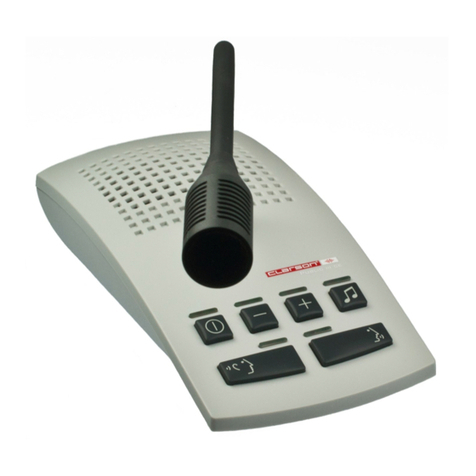
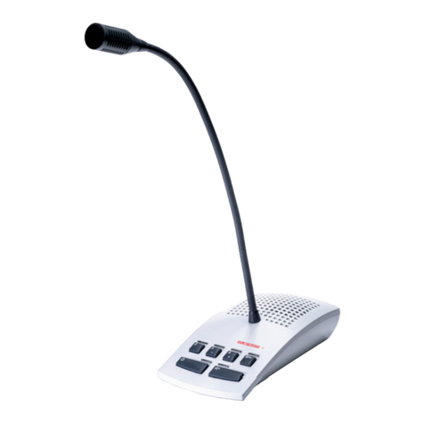
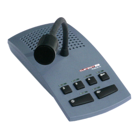
Clarson PUBLIC III User manual

public III
Operating and Installation Instructions
Bedienings-en montagehandleiding
Instructions de Service et de Montage

Index
Index
Sommaire
Eigenschappen/ Features / Caractéristiques................................................3
Aansluiting microfoon/luidspreker unit..........................................................4
Connecting the microphone loudspeaker unit...............................................4
Brancher le pupitre micro/haut-parleur.........................................................4
Standaard werkingsmode.............................................................................5
Standard operating mode.............................................................................5
Mode opératoire standard ............................................................................5
Push-to-talk werkingsmode..........................................................................6
Push to talk mode ........................................................................................6
Mode opératoire appuyer pour parler...........................................................6
Boost werkingsmode....................................................................................7
Boost mode..................................................................................................7
Mode booster...............................................................................................7
Standaard werkingsmode wijzigen (Standaard-Push to talk-Boost)..............8
Changing the operating mode (standard - push to talk -
boost ) ...................8
Changer le mode opératoire (standard - appuyer pour parler - booster ...... 8
Posten klantzijde selecteren / deuropening functie ......................................9
Selecting a public side position / door lock release.......................................9
Sélectionner une position côté public / commande de gâche .......................9
Activatie interface headset/handset............................................................10
Activating the headset/handset interface ..................................................10
Activer l´interface micro-casque/combiné ..................................................10
Interface headset/handset geactiveerd.......................................................11
Headset/handset interface activated ..........................................................11
Interface micro-casque/combiné activée ....................................................11
Montage-instructies...............................................................................12/13
Afstellingen ................................................................................................14
Aansluiting connectoren op de Centrale Eenheid en legende.....................15
Installation Instructions..........................................................................16/17
Adjustment.................................................................................................18
Assignment of terminals at the central unit and legend...............................19
Instructions de Montage........................................................................20/21
Réglage......................................................................................................22
Brochage des prises de l´unité centrale et légende....................................
23
2

Eigenschappen/ Features / Caractéristiques
Open duplextechnologie
Tijdelijke volumetoename
Mute-functie aan bedieningszijde (Push-to-talk)
Afzonderlijk instelbare microfoongevoeligheid aan bedienings-en klantzijde
Onderhoudsvriendelijk d.m.v. connectoren RJ45
Verhoogde storingsbeveiliging door gebalanceerde audio in-en uitgangen
Laag verbruik wanneer systeem afgezet is (< 0,2 W)
Afzonderlijke inductie versterker voor bedienings-en klantzijde*
Inductie versterker aan bedieningszijde kan ook voor de klantzijde gebruikt worden*
Tot 2 bedieningsposten*
Tot 4 klantposten*
Oproeptoets (digitale gong) voor bedieningsposten met instelbare geluidsterkte*
Toets voor deuropening/relais*
Interface headset/handset met volumeregeling*
Gemakkelijk omschakelen tussen verschillende werkingsmodes Standaard, Push to
talk, Versterker
*Optie
Open duplex technology
Temporary volume increase
Microphone mute on service side (Push to talk)
Individual service and public side microphone squelch sensitivity control
Fast and error free installation via RJ45 sockets
Increased interference immunity due to balanced audio in- and outputs
Low power consumption when system is switched off (< 0,2 W)
Separate service and public side induction amplifier *
Service side induction amplifier also usable for public side *
Up to 2 service side positions *
Up to 4 public side positions *
Call button (gong) for public side positions with gong volume control *
Door lock release button *
Headset/handset interface with volume control *
Easy mode changeover standard, push to talk, boost
*Option
Interphonie en duplex intégral
Augmentation temporaire du volume sonore
Verrouillage micro côté service (Push to talk)
Réglage individuel de la sensibilité du micro (squelch) côté service et public
Maintien simple par prises RJ45
Protection élevée contre les parasites par des entrées et sorties audio symétriques
Puissance absorbée faible hors service (< 0,2 W)
Amplificateur d´induction séparé pour côté service et public *
Amplificateur côté service aussi utilisable pour coté public *
Jusqu´à 2 positions côté service *
Jusqu´à 4 positions côté public *
Touche d´appel (carillon digital) sur positions public avec réglage volume carillon digital *
Touche commande de gâche *
Interface micro-casque/combiné avec réglage volume *
Changement simple des modes opératoires standard, appuyer pour parler, booster
*Option
NL
E
F
3

Aansluiting microfoon/luidspreker unit
Connecting the microphone loudspeaker unit
Brancher le pupitre micro/haut-parleur
Brancher le câble sur prise 1 (indispensable), reliant le pupitre micro/hp avec
l´unité centrale.
Brancher le câble sur prise 2 au cas où le pupitre micro/hp est muni d´un
micro-casque ou combiné.
Brancher le micro-casque/combiné sur prise
F
Link the microphone loudspeaker unit with the central unit at jack 1 (indispensable
connection).
Plug the cable into jack 2 if the microphone loudspeaker unit is configurated for
headset/handset operation.
Connect the headset/handset at jack
E
Sluit de microfoon/luidspreker unit aan met de Centrale Eenheid bij connector 1
(noodzakelijke aansluiting).
Connector 2 met de Centrale Eenheid aansluiten.
Deze aansluiting is alleen noodzakelijk, wanneer aan de microfoon/luidspreker unit
een headset/handset aangesloten wordt. Aan connector kan een headset/ handset
worden aangesloten.
4
NL

STANDAARD werkingsmode
STANDARD Operating Mode
Mode Opératoire STANDARD
Opzetten:
Druk op toets !, de LED
bovenaan de toets licht op.
Afzetten:
Druk op de toets !, de LED
bovenaan de toets gaat uit.
Switching on:
Push button !, the led
above the button lights up.
Switching off:
Push button !, the led
above the button goes out.
Mise en marche:
Appuyer sur la touche !,
la led au-dessus de la
touche s´allume.
Arrêt:
Réappuyer sur la touche !,
la led au-dessus de la
touche s´éteint.
E
F
NL
Op-en afzetten
Switching ON/Off
Mise en marche/arrêt
De toets “ ingedrukt
houden.
De LED bovenaan de toets
licht op.
Het volume aan de bedie-
ningszijde is verhoogd met
10dB en tegelijkertijd afge-
nomen met 10dB aan de
klantzijde.
Push and hold button ".
The led above the button
lights up.
The volume on the service
side is increased by 10dB
and at the same time
decreased by 10dB on
the public side.
Appuyer la touche "en
continu.
La led au-dessus de la
touche s´allume.
Le volume d´écoute sur le
côté service est augmenté
par 10dB et en même
temps diminué par 10db
sur le côté public.
E
F
NL
Volumetoename
Volume increase
Augmenter le volume
5

PUSH TO TALK - werkingsmode
PUSH TO TALK Mode
Mode Opératoire APPUYER POUR PARLER
Het systeem op-en afzetten
Switching the system ON/OFF
Mise en marche/arrêt
Opzetten:
Druk op toets !, de LED
bovenaan de toets licht op.
Afzetten:
Hou de toets “ ingedrukt (de
LED bovenaan de toets licht
op) en tegelijkertijd de toets !
kort induwen. De
LED’s bovenaan de toetsen ! “
gaan uit.
Switching on:
Push button !, the led above
the button flashes.
Switching off:
Push and hold button "(the led
above the button lights up) and
simultaneously tap on button !.
The leds above buttons ! " go
out.
Mise en marche:
Appuyer sur la touche !, la
led au-dessus de la touche
clignote.
Arrêter:
Appuyer la touche "en
continu (la led au-dessus de la
touche s´allume) et en même
temps appuyer brièvement sur
la touche !. Les leds au-dessus
des touches ! " s´éteignent.
NL
E
F
Spreken
Speak
Parler
Toets !ingedrukt houden.
De LED bovenaan de
toets licht op.
Push and hold button !.
The led above the button
lights up.
Appuyer la touche !en
continu.
La led au-dessus de la
touche s´allume.
NL
E
F
Volumetoename
Volume increase
Augmenter le volume
Toets “ ingedrukt houden.
De LED bovenaan de toets
licht op.
Het volume aan de bedie-
ningszijde is verhoogd met
10dB en tegelijkertijd afge-
nomen met 10dB aan de
klantzijde.
Press and hold button ".
The led above the button
lights up.
The volume on the service
side is increased by 10dB
and at the same time
decreased by 10dB on
the public side.
Appuyer la touche "en
continu.
La led au-dessus de la
touche s´allume.
Le volume d´écoute sur le
côté service est augmenté
par 10dB et en même
temps diminué par 10db
sur le côté public.
E
F
NL
6

BOOST - werkingsmode
BOOST MODE
Mode BOOSTER
Horen / Spreken
Listen / Speak
Ecouter / Parler
Het systeem op-en afzetten
Switching the system ON/OFF
Mise en marche/arrêt
Opzetten:
Toets ! indrukken.
De LED’s bovenaan de toet-
sen ! " lichten op.
Afzetten:
Toets ! indrukken, de LED’s
bovenaan de toetsen ! “gaan
uit.
Switching on:
Push button !.
The leds above buttons ! "
light up.
Switching off:
Push button !.
The leds above buttons ! "
go out.
Mise en marche:
Appuyer sur la touche !.
Les leds au-dessus des tou
ches ! " s´allument.
Arrêter:
Appuyer sur la touche !.
Les leds au-dessus des tou
ches ! " s´éteignent.
NL
E
F
Indezemodeishetvolumeaande
bedieningszijdeverhoogdmet10dBen
verlaagdmet10dBaandeklantzijde.
DeLEDbovenaandetoets“licht
op.Omtesprekenhoudetoets“in-
gedrukt.Hetvolumeaandebedienings-
zijdeisverlaagdmet10dBen
verhoogdmet10dBaandeklantzijde.
DeLEDbovenaandetoetsgaatuit.
In this mode the volume on the
service side is increased by 10dB
and decreased by 10dB on the
public side.
The led above button "lights up.
For speaking push and hold button
The volume on the service side is
decreased by 10dB and increased
by 10dB on the public side.
The led above the button goes out.
Dans ce mode le volume d´écoute
sur le côté service est augmenté
par 10dB et diminué par 10db sur le
côté public. La led au-dessus de la
touche "s´allume.
Appuyer la touche "en continu pour
parler. Le volume d´écoute sur le
côté service est diminué par 10dB
et augmenté par 10dB sur le côté
public. La led au-dessus de la tou-
che s´éteint.
NL
E
F
7

Verandering van werkingsmode
Changing the Operating Mode
Changer le Mode Opératoire
Standaard - mode
Standard Operating Mode
Mode Opératoire Standard
Push to talk - mode
Push to talk Mode
Mode Appuyer pour parler
Boost - mode
Boost Mode
Mode Booster
Systeem afzetten.
Toets ! zo lang ingedrukt
houden totdat de LED één
keer oplicht.
Om terug te keren naar de
standaard mode, druk terug
op de toets ! of trek de
voedingskabel voor enkele
ogenblikken uit.
Switch the system off.
Push and hold button till
the led flashes once.
To return to standard mode,
push button again or
disconnect the system from
the mains for a moment.
Mettre le système hors ten-
sion.
Laisser la touche appuyée
jusqu´à ce que la led clignote
une fois.
Pour retourner au mode stan-
dard, réappuyer sur la touche
ou retirer le câble d´ali-
mentation pendant quelques
instants.
Systeem afzetten.
Toets ! zo lang ingedrukt
houden totdat de LED
twee keer oplicht.
Om terug te keren naar de
standaard mode, druk
terug op de toets ! of trek
de voedingskabel voor
enkele ogenblikken uit.
Switch the system off.
Push and hold button till
the led flashes twice.
To return to standard mode,
push button again or
disconnect the system from
the mains for a moment.
Mettre le système hors
tension.
Laisser la touche appuyée
jusqu´à ce que la led clignote
deux fois.
Pour retourner au mode stan-
dard, réappuyer sur la touche
ou retirer le câble d´ali-
mentation pendant quelques
instants.
Het systeem functioneert
volgens de standaard
mode na ingebruikname en
druk op de toets ! .
After starting the system
and pushing button ,
the system operates in
standard mode.
Le système fonctionne en
mode standard après mise
en route et appui sur la
touche .
NL
E
F
NL
E
F
NL
E
F
8

OPTIES / OPTIONS
Posten klantzijde selecteren / Deuropening functie
Selecting a Public Side Position / Door Lock Release
Sélectionner une Position Côté Public/Commande deGâche
Posten klantzijde 2 / 3 / 4
Public Side Positions 2 / 3 / 4
Positions Côté Public 2 / 3 / 4
Wanneer de oproeptoets aan de
klantzijde 2/3/4 ingedrukt wordt, zal
de LED bovenaan de toetsen 2/3/4
van de microfoon/luidspreker unit
oplichten.
Communicatie met de posten aan
de klantzijde 2/3/4 kan beginnen
door te drukken op de toetsen 2/3/4.
De corresponderende LED blijft
branden.
If the call button on public side
position 2/3/4 is activated, the
led above the button 2/3/4 on the
microphone loudspeaker unit
flashes.
Communication with public side
position 2/3/4 is established by
activating the button.
The corresponding led above the
button lights permanently.
Si la touche d´appel sur la position
côté public 2/3/4 est appuyée, la led
correspondante au-dessus de la
touche 2/3/4 sur le pupitre micro/hp
clignote.
La communication est établie en
appuyant sur la touche 2/3/4 et la
led au-dessus de la touche est
allumée en continu.
NL
E
F
Toets * ingedrukt houden.
De LED bovenaan de toets licht op.
De deuropening functie aan de
corresponderende post klantzijde is
geactiveerd.
Push and hold button *.
The led above the button lights up.
The door lock release function on
the corresponding public side
position is activated.
Appuyer la touche * en continu.
La led au-dessus de la touche
s´allume.
La fonction commande de gâche
sur la position public correspon-
dante est activée.
E
F
NL
Deuropening functie
Door Lock Release
Commande de Gâche
9

OPTIES/ OPTIONS
Activatie interface HEADSET/HANDSET
Activating the HEADSET/HANDSET Interface
Activer l´interface MICRO-CASQUE/COMBINE
Bedieningszijde
Service Side
Côté Service
Klantzijde
Public Side
Côté Public
Systeem afzetten.
Toets “ zo lang ingedrukt hou-
den totdat de LED bovenaan de
toets één keer oplicht.
Om te annuleren, druk terug op
deze toets of trek de voedingska-
bel voor enkele ogenblikken uit.
Deze stappen kunnen geautoma-
tiseerd worden door een extern
contact in de handset.
Switch the system off.
Push and hold button till the led
above the button flashes
once.
Return to previous mode by re-
peating the above mentioned
steps or by disconnecting the
system from the mains for a
moment.
This process can be automized,
e.g. by an external contact in the
handset support.
Mettre le système hors tension.
Laisser la touche appuyée jus-
qu´à ce que la led au-dessus de
la touche clignote une fois.Pour
annuler, réappuyer sur la touche
ou retirer le câble d´ali-mentation
pendant quelques instants.
Cette opération peut être auto-
matisée par l´intermédiaire d´un
contact externe p. ex. dans le
support du combiné.
NL
E
F
Systeem afzetten.
Toets “ zo lang ingedrukt
houden totdat de LED bovenaan
de toets tweemaal oplicht.
Om te annuleren, druk terug op
deze toets of trek de voedingska-
bel voor enkele ogenblikken uit.
Deze stappen kunnen geautoma-
tiseerd worden door een extern
contact in de handset.
Switch the system off.
Push and hold button till the led
above the button flashes
twice.
Return to previous mode by re-
peating the above mentioned
steps or by disconnecting the
system from the mains for a
moment.
This process can be automized,
e.g. by an external contact in the
handset support.
Mettre le système hors tension.
Laisser la touche appuyée jus-
qu´à ce que la led au-dessus de
la touche clignote deux fois.
Pour annuler, réappuyer sur la
touche ou retirer le câble
d´alimentation pendant quelques
instants.
Cette opération peut être auto-
matisée par l´intermédiaire d´un
contact externe p. ex. dans le
support du combiné.
NL
E
F
10

OPTIES / OPTIONS
Interface HEADSET/HANDSET geactiveerd
HEADSET/HANDSET Interface activated
Interface MICRO-CASQUE/COMBINE activée
Klantzijde
Public Side
Côté Public
De microfoon en luidspreker
aan de klantzijde zijn niet
geactiveerd. Het oplichten
van de LED
(1 sec aan-0,2 sec uit)
bovenaan de toets ! duidt dit
aan.
The microphone and loud-
speaker on the public side
are not activated.
The flashing led (1 sec on -
0,2 sec off) above button
indicates this mode.
Le microphone et le haut-
parleur sur le côté public
sont coupés.
La led au-dessus de la
touche clignote
(1 sec allumée - 0,2 sec
éteinte) indiquant l´étát du
système.
Bedieningszijde
Service Side
Côté Service
Bedienings-en klantzijde
Service + Public Side
Côté Service + Public
NL
De microfoon en luidspre-
ker aan de bedieningszijde
zijn niet geactiveerd. Het
oplichten van de LED
(intervals van 0.5 sec)
bovenaan de toets ! duidt
dit aan.
The microphone and loud-
speaker on the service side
are not activated.
The flashing led (intervals
of 0,5 sec) above button
indicates this mode.
Le microphone et le haut-
parleur sur le côté service
sont coupés.
La led au-dessus de la
touche clignote (intervalle
de 0,5 sec) indiquant l´état
du système.
NL
E
F
E
F
De microfoon en luidspreker
aan de bedienings-en
klantzijde zijn niet
geactiveerd. Het oplichten
van de LED (1 sec aan-0,2
sec uit;0,2 sec aan-0,2 sec
uit) bovenaan de toets ! duidt
dit aan.
The microphone and loud-
speaker on public and
service side are not activa-
ted.
The flashing led
(1 sec on - 0,2 sec off -
0,2 sec on - 0,2 sec off)
above button indicates
this mode.
Le microphone et le haut-
parleur sur le côté public
et service sont coupés.
La led au-dessus de la
touche clignote
(1 sec allumée - 0,2 sec
éteinte - 0,2 sec allumée -
0,2 sec éteinte) indiquant
l´état du système.
NL
E
F
11

Montagetips:
1.Elke opening tussen de bedienings-en klantzijde zal de performantie van het
systeem beïnvloeden.
Hoe meer het loket gesloten blijft, des te meer zal het interfoniesysteem goed
functioneren.
2.Plaats de luidspreker zo dicht mogelijk bij het oor van de luisteraar. Plaats de
microfoon zo dicht mogelijk bij de mond van de spreker en zo ver mogelijk van de
luidspreker.
3. Luidspreker/klantzijde: aan de zijkant op 1,50-1,60m van de grond (optimale positie).
Boven het hoofd op een hoogte van maximum 2,10m van de grond.
Microfoon/klantzijde: 1,30-1,50m van de grond.
Minimum afstand tussen microfoon en luidspreker: 0,5m.
4. Spreekafstand tot de microfoon:
Bedieningszijde: 10-30cm
Klantzijde:
omnidirectionele electret inbouw microfoon (40.005.017/40.005.053): max. 50 cm
directionele electret microfoon (40.005.050/40.005.051): max. 30 cm
Montagehandleiding
12

+
-
GND
Microfoon
367
Luidspreker
4 5
Optie slechthorenden
(Inductiestaafje)
4 5 bediening 3 6 klant
Bu1 Bu2
1. Montage van
de Centrale
Eenheid
1.1 Contactdoos/dozen RJ45 installeren (1 contactdoos voor elke
post klantzijde).
1.2 Schroef de Centrale Eenheid vast met vier vijzen onder de
tafel of tegen de muur.
2. Aansluiting
van de
componenten
2.1 Installeer alle microfoons en luidsprekers en sluit deze aan aan de
contactdoos RJ45 (fig 1). Contactdoos RJ45 (Bu1) en de Centrale
Eenheid (connector klant) met patchkabel aansluiten (fig2).
OPTIES: Oproeptoets, digitale gong, relais, inductiestaafje;
eveneens aan contactdoos RJ45 aansluiten. (zie blz. 15)
Contactdoos RJ45 (Bu2) en de Centrale Eenheid (connector loop)
met patchkabel aansluiten.
2.2 De microfoon/luidspreker unit (connector 1) en de Centrale Eenheid
(connector bediening) aansluiten met patchkabel (fig 2).
OPTIES:Headset/Handset
De microfoon/luidspreker unit (connector 2) en de Centrale Eenheid
(connector headset) aansluiten met patchkabel en sluit de headset/
handset aan op de microfoon/luidspreker unit (connector ?).
Niet van toepassing wanneer de headset/handset rechtstreeks is
aangesloten op de Centrale Eenheid (connector headset).
2.3 Sluit de voeding aan op de Centrale Eenheid (connector DC power)
(fig 2).
FIG 1
13

3. Afstellingen
De potentiometers bevinden zich aan de achterzijde van de Centrale Eenheid. Deze zijn
vooraf ingesteld in de fabriek en moeten onder normale omstandigheden niet aangepast
worden. Gebruik de potentiometers niet vooraleer het systeem geïnstalleerd en in
werking is gesteld. Wanneer potentiometers moeten aangepast worden, gebruik dan een
schroevendraaier van 2.5 mm (niet smaller dan 2mm). Voor optimalisering ga als volgt tewerk:
FIG 2
3.1 Maak de Centrale Eenheid los en leg het op tafel voor verdere aanpassingen.
3.2 Druk op de toets ! om het systeem op te zetten. De groene LED licht op.
Notitie: De maximale verdeelbare geluidssterkte (100%) is gelimiteerd. Dit volume kan
verdeeld worden tussen de bedienings-en klantzijde (bv. 40% bedieningszijde, 60%
klantzijde).
3.3 Volumeregeling bedieningszijde:
Regel de potentiometer (ser+luidspreker) terwijl iemand spreekt aan de klantzijde.
3.4 Volumeregeling klantzijde:
Regel de potentiometer (pub+luidspreker) terwijl iemand spreekt aan de bedieningszijde.
3.5 Om de volumeregeling na te kijken, houd uw hand op 4cm van de microfoon van de
bedieningszijde. De installatie mag niet fluiten!
3.6 De gevoeligheid van de microfoons bedienings-en klantzijde is afgesteld in de fabriek en
moet niet worden aangepast behalve i.g.v. extreme akoestische situaties, bv. hoge
omringende geluidsniveaus aan de klantzijde.
3.7 Stel de potentiometers van de bijkomende aangesloten componenten af, bv.
aanvullende posten klantzijde, headset enz.
3.8 De Centrale Eenheid terug vastmaken en schroef deze definitief vast.
14

15

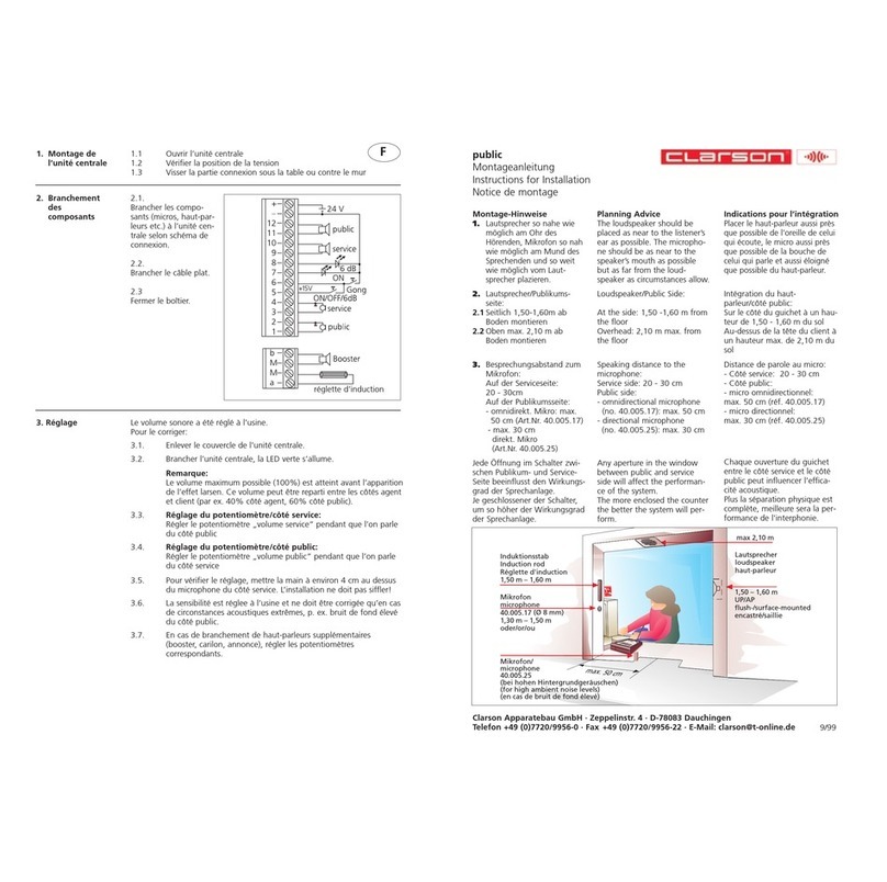
Planning Advice
1. Any aperture in the window between public and service side will affect the
performance of the system.
The more enclosed the counter, the better the system will perform.
2.The loudspeaker should be placed as near to the listener´s ear as possible.
The microphone should be as near to the speaker´s mouth as possible,
but as far from the loudspeaker as circumstances allow.
3. Loudspeaker/public side (from the ground): at the side 1,50-1,60 m,overhead max.2,10 m
Microphone/public side (from the ground): 1,30 - 1,50 m,
minimum distance between microphone and loudspeaker: 0,5 m
4. Speaking distance to the microphone:
Service side: 10 - 30 cm
Public side:
omnidirectional microphone (40.005.017/40.005.053): max. 50 cm
directional microphone (40.005.050/40.005.051): max. 30 cm
Installation Instructions
16

+
-
GND
microphone
367
loudspeaker
4 5
optional loop
(induction rod)
4 5 service 3 6 public
Bu1 Bu2
1. Installation
of the
central unit
1.1 Install the RJ45 socket/s (1 socket for each public side position)
1.2 Screw the central unit provisionally on the wall or under the
desk (4 screws).
2. Installation
of
components
2.1 Install the microphones and loudspeakers and connect them to
the RJ45 socket (pict. 1). Link the RJ45 socket (Bu1 ) with the
central unit (jack public) via patch cable (pict. 2).
OPTIONS: Connect any additional equipment, e. g. call button,
gong, relay box, loop (induction rod) also to the RJ45 socket
(see page 19). Link the RJ45 socket (Bu2) with the central unit
(jack loop) via patch cable.
2.2 Link the microphone loudspeaker unit (jack 1) with the central
unit (jack service) via patch cable (pict. 2).
OPTION:Headset/Handset
Link the microphone loudspeaker unit (jack 2) with the central
unit (jack headset) via patch cable and connect the headset/
handset to the microphone loudspeaker unit (jack ).
Not applicable if the headset/handset is connected directly to
the central unit (jack headset).
2.3 Connect the power supply to the central unit (DCjack)(pict.2).
pict. 1
17

pict. 2
3. Adjustment
The potentiometers are located at the rear of the central unit. They have been pre-set
at the factory and do not need to be adjusted under normal conditions. Do not turn
potentiometers before the system has been installed and is in working order.
If potentiometers need to be set, use a 2.5 mm (not smaller than 2 mm) flat blade
screwdriver. For readjustment/optimisation proceed as follows:
3.1 Remove the central unit and place it on the table for comfortable adjustment.
3.2 Push button to switch the system on. The green led lights up.
Note:
Max. volume (100 %) is reached slightly before feedback. This volume can be
distributed between service and and public side (e. g. 40 % service side, 60 %
public side).
3.3 Volume/Service Side:
Tune potentiometer whilst somebody is speaking on the public side.
3.4 Volume/Public Side:
Tune potentiometer whilst somebody is speaking on the service side.
3.5 Place your hand about 4 cm over the center hole of the microphone on the service
side. Feedback must be avoided!
3.6 The sensitivity of the service/public side microphone is adjusted in our factory.
It should only be changed in case of extreme acoustical conditions, e. g. in case of
high ambient noise levels on the public side.
3.7 Tune the potentiometers of additionally connected components, e. g. further public
positions, headset etc.
3.8 Suspend and definitely screw the central unit.
!
#
$
18

19

Indications pour l´intégration
1.Chaque ouverture du guichet entre le côté service et le côté public peut influencer
l´efficacité acoustique.
Plus la séparation physique est complète, meilleure sera la performance de
l´interphonie.
2.Placer le haut-parleur aussi près que possible de l´oreille de celui qui écoute et
le microphone aussi près que possible de la bouche de celui qui parle et aussi
éloigné que possible du haut-parleur.
3. Haut-parleur/côté public (hauteur du sol): sur le côté 1,50 - 1,60 m,
au-dessus de la tête max. 2,10 m
Microphone/côté public (hauteur du sol): 1,30 - 1,50 m
distance minimum entre microphone et haut-parleur: 0,5 m.
4. Distance de parole au micro:
côté service: 10 - 30 cm
côté public:
microphone omnidirectionnel (40.005.017/40.005.053): max. 50 cm
microphone directionnel (40.005.050/40.005.051): max. 30 cm
Instructions de montage
20
Other manuals for PUBLIC III
3
Table of contents
Other Clarson Intercom System manuals
