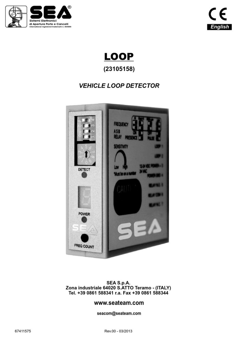
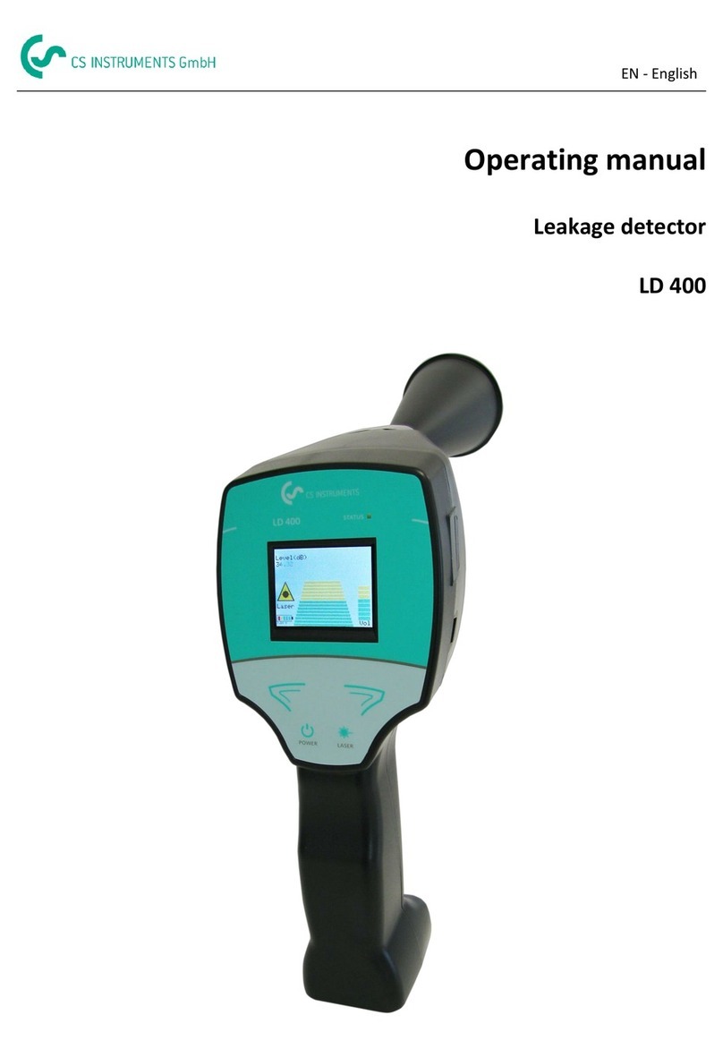
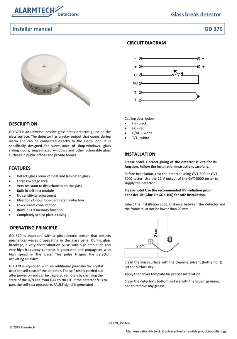
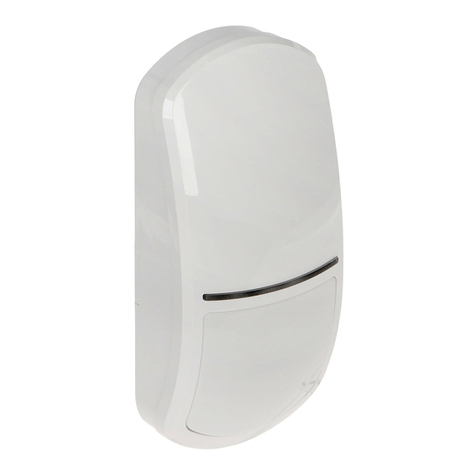
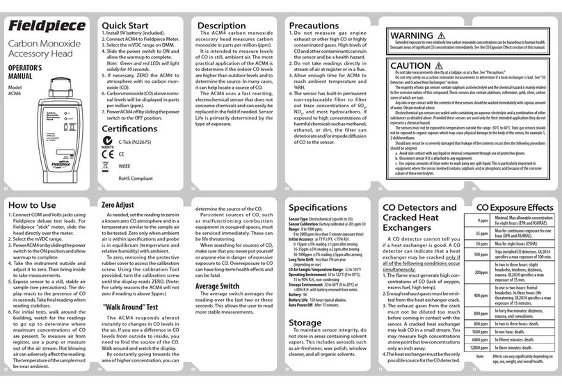
SEA LOOP 2 User manual

Sistemi Elettronici
di Apertura Porte e Cancelli
International registered trademark n. 804888
®
LOOP 2
Spira rilevamento veicoli
Vehicle Loop Detector
Italiano
67411510
Istruzioni - Operating instructions
Questo prodotto è un accessorio o una parte di un sistema. Leggere e seguire
sempre le istruzioni del produttore dell'apparecchio al quale state collegando
questo prodotto. Rispettare tutte le regolazioni di sicurezza. La non osservanza potrebbe
causare danni, lesioni o morte.
Rev.01 - 05/201367411510
English

LOOP 2
LOOP 2
LOOP 2
LOOP 2
24 Volt DC
Sistemi Elettronici
di Apertura Porte e Cancelli
International registered trademark n. 804888
®
67411510 Rev.01 - 05/2013 7
English
LOOP 2

0V)
24V DC)
9 10 11 1 2 3
4 5 6 7 8
Sistemi Elettronici
di Apertura Porte e Cancelli
International registered trademark n. 804888
®
67411510 Rev.01 - 05/20138
Controls, Indicators and Connections
Front Back
POWER LED
Green T-1 Glows when power is applied
DETECT LED
3/4
Red T-1 Glows to indicated detection
FREQUENCY
COUNTER
Pull up toward Power LED and release
Momentary Switch
RESET Momentary Switch
Push down toward Freq. and release
FREQUENCY Three position Switch
Low, High, Medium
Unit must be reset after any change!
SENSITIVITY BCD Switch
0,1,2,3,4,5,6,7,8,9 must be on a number
DIP SWITCH FUNCTIONS
DIP switch
OFF ON
1 Pulse on relay 2 Presence on relay 2
2
8
Pulse on Detect Pulse on Un-detect
Costant presence
34 minute limited
presence time
“Fail Secure” “Fail Safe”
4
5 Filter OFF Filter ON
ASB OFF Automatic Sensitivity
Boost
6
Extended Detect 6 seconds
7
3 seconds
DIP 7 & 8 ON Extend time is 9 seconds
For more details see page 9 and 10.
Extended Detect
CONNECTIONS
PIN FUNCTION
1 POWER +
2 POWER -
3 RELAY 2 N/O
(IPUSE OR PRESENCE)
4* GROUND*
5 PRESENCE RELAY (1) COM
6** PRESENCE RELAY (1) N/O
7 LOOP
8 LOOP
RELAY 2 COM
(PULSE OR PRESENCE)
9
10** PRESENCE RELAY (1) N/C
RELAY 2 N/C
(PULSE OR PRESENCE)
11
* NOTA: Pin 4 must be connected to earth ground
for surge protection to be effective.
**NOTE: Functions on pins 6 and 10 are reserved
if DIP switch 4 is set to OFF “Fail Secure”
operation.
English

LOOP 2
LOOP 2
LOOP 2
LOOP 2
. The
Pin 4
8
7
Sistemi Elettronici
di Apertura Porte e Cancelli
International registered trademark n. 804888
®
67411510 Rev.01 - 05/2013 9
English

Sistemi Elettronici
di Apertura Porte e Cancelli
International registered trademark n. 804888
®
67411510 Rev.01 - 05/201310
English

REALISATION OF THE SENSITIVE ELEMENT (FIG. 1)
The detectors are suitable for coils made up with an insulated copper wire with a cross-section of at least 1.5 sq.
mm. Preferably use twisted copper wires with at least 20 twists per metre to connect the detector to the coil.
Jointing in the coil wires and in the twisted cable is not recommended. If the wires used for the twisted cable are
especially long or in proximity to other power cables, shielding of said wires is recommended. Earthing of the shield
should only be made at the extremity of the detector.
Excepting special cases, the detection coils should be rectangular. Install with the longer sides placed at right angles in
the direction of vehicle movement. These sides should ideally be kept at a meter one from the other. Coil length is a
function of the width of the road surface to be monitored.A distance of no more than 300 mm is recommended between
the coil and each edge of the road surface. For coils running over a perimeter of more than ten metres two wire windings
are normally employed, while for coils with a lower perimeter three or more windings are required, and four windings are
required for coils with a perimeter below six metres.
All permanent coil components must be secured to the road surface in appropriate grooves made using masonry
cutting tools or the like. A cross-cut at a 45° inclination must be made at the circuit angles so as to prevent the risk of the
coil cable being damaged in proximity to the apex of the right angles.
Nominal groove length: 4 mm.
Nominal groove depth: 50 mm.
The coil-detector connection cable must also be laid in an appropriate groove running from one of the circuit angles
along the circuit perimeter to the road surface edge. To ensure wiring continuity between the coil and connection cable
allow for a long enough lead to reach as far as the detector before inserting the cable inside the coil groove. After laying
the required number of wire windings in the groove along the coil perimeter, route the wire towards the road edge
through the connection cable groove.
It is advisable that connection cable length not exceed 100 metres. As coil sensitivity diminishes proportionally to
connection cable length the latter should be kept as short as possible.
Coils are secured to road surface by means of a quick-drying compound containing epoxy resin or asphalt mastic
applied hot.
2
1.5 mm section cable
Cable width
Groove
depth
Fig. 1
0,3 m
max. 1 m
max. 5 m
0,3 m
At least 3 turns are recommended
At least 20 twists per metre
Note:It is advisable to use an only piece of uninterrupted cable to forme the loop. Therefore, it is preferable to make a
preliminary of the cable length.
Ex. (Perimeter loop per twists) + distance of the module + 200 mm.
15 mm
25
mm
Sistemi Elettronici
di Apertura Porte e Cancelli
International registered trademark n. 804888
®
67411510 Rev.01 - 05/2013 11
English

Sistemi Elettronici
di Apertura Porte e Cancelli
International registered trademark n. 804888
®
67411510 Rev.01 - 05/201312
English

Sistemi Elettronici
di Apertura Porte e Cancelli
International registered trademark n. 804888
®
67411510 Rev.01 - 05/2013
AVVERTENZE GENERALI PER INSTALLATORE E UTENTE
1. Leggere attentamente le Istruzioni di Montaggio e le Avvertenze Generali prima di iniziare
l’installazione del prodotto. Conservare la documentazione per consultazioni future
2. Non disperdere nell’ambiente i materiali di imballaggio del prodotto e/o circuiti
3. Questo prodotto è stato progettato e costruito esclusivamente per l’utilizzo indicato in questa
documentazione. Qualsiasi altro utilizzo non espressamente indicato potrebbe pregiudicare l’integrità del
prodotto e/o rappresentare fonte di pericolo. L’uso improprio è anche causa di cessazione della garanzia. La
SEA S.p.A. declina qualsiasi responsabilità derivata dall’uso improprio o diverso da quello per cui
l’automatismo è destinato.
4. I prodotti SEA sono conformi alle Direttive: Macchine (2006/42/CE e successive modifiche), Bassa
Tensione (2006/95/CE e successive modifiche), Compatibilità Elettromagnetica (2004/108/CE e
successive modifiche). L’installazione deve essere effettuata nell’osservanza delle norme EN 12453 e EN
12445.
5. Non installare l’apparecchio in atmosfera esplosiva.
6. SEAS.p.A. non è responsabile dell’inosservanza della Buona Tecnica nella costruzione delle chiusure da
motorizzare, nonché delle deformazioni che dovessero verificarsi durante l’uso.
7. Prima di effettuare qualsiasi intervento sull’impianto, togliere l’alimentazione elettrica e scollegare le
batterie. Verificare che l’impianto di terra sia realizzato a regola d’arte e collegarvi le parti metalliche della
chiusura.
8. Per ogni impianto SEA S.p.A. consiglia l’utilizzo di almeno una segnalazione luminosa nonché di un
cartello di segnalazione fissato adeguatamente sulla struttura dell’infisso.
9. SEA S.p.A. declina ogni responsabilità ai fini della sicurezza e del buon funzionamento della
automazione, in caso vengano utilizzati componenti di altri produttori.
10. Per la manutenzione utilizzare esclusivamente parti originali SEA.
11. Non eseguire alcuna modifica sui componenti dell’automazione.
12. L’installatore deve fornire tutte le informazioni relative al funzionamento manuale del sistema in caso di
emergenza e consegnare all’Utente utilizzatore dell’impianto il libretto d’avvertenze allegato al prodotto.
13. Non permettere ai bambini o persone di sostare nelle vicinanze del prodotto durante il funzionamento.
L’applicazione non può essere utilizzata da bambini, da persone con ridotte capacità fisiche, mentali,
sensoriali o da persone prive di esperienza o del necessario addestramento. Tenere inoltre fuori dalla
portata dei bambini radiocomandi o qualsiasi altro datore di impulso, per evitare che l’automazione possa
essere azionata involontariamente.
14. Il transito tra le ante deve avvenire solo a cancello completamente aperto.
15. Tutti gli interventi di manutenzione, riparazione o verifiche periodiche devono essere eseguiti da
personale professionalmente qualificato. L’utente deve astenersi da qualsiasi tentativo di riparazione o
d’intervento e deve rivolgersi esclusivamente a personale qualificato SEA. L’utente può eseguire solo la
manovra manuale.
16. La lunghezza massima dei cavi di alimentazione fra centrale e motori non deve essere superiore a 10 m.
2
Utilizzare cavi con sezione 2.5 mm . Utilizzare cablaggi con cavi in doppio isolamento (cavi con guaina) nelle
immediate vicinanze dei morsetti specie per il cavo di alimentazione (230V). Inoltre è necessario mantenere
adeguatamente lontani (almeno 2.5 mm in aria) i conduttori in bassa tensione (230V) dai conduttori in
bassissima tensione di sicurezza (SELV) oppure utilizzare un’adeguata guaina che fornisca un isolamento
supplementare avente uno spessore di almeno 1 mm.
13
Italiano

67411510 Rev.01 - 05/2013
Sistemi Elettronici
di Apertura Porte e Cancelli
International registered trademark n. 804888
®
GENERAL NOTICE FOR THE INSTALLER AND THE USER
1. Read carefully these Instructions before beginning to install the product. Store these instructions for
future reference
2. Don’t waste product packaging materials and /or circuits.
3. This product was designed and built strictly for the use indicated in this documentation.Any other use, not
expressly indicated here, could compromise the good condition/operation of the product and/or be a source
of danger. SEA S.p.A. declines all liability caused by improper use or different use in respect to the intended
one.
4. The mechanical parts must be comply with Directives: Machine Regulation 2006/42/CE and following
adjustments), Low Tension (2006/95/CE), electromgnetic Consistency (2004/108/CE) Installation must be
done respecting Directives: EN12453 and En12445.
5. Do not install the equipment in an explosive atmosphere.
6. SEA S.p.A. is not responsible for failure to observe Good Techniques in the construction of the locking
elements to motorize, or for any deformation that may occur during use.
7. Before attempting any job on the system, cut out electrical power and disconnect the batteries. Be sure
that the earthing system is perfectly constructed, and connect it metal parts of the lock.
8. Use of the indicator-light is recommended for every system, as well as a warning sign well-fixed to the
frame structure.
9. SEAS.p.A. declines all liability as concerns the automated system’s security and efficiency, if components
used, are not produced by SEAS.p.A..
10. For maintenance, strictly use original parts by SEA.
11. Do not modify in any way the components of the automated system.
12. The installer shall supply all information concerning system’s manual functioning in case of emergency,
and shall hand over to the user the warnings handbook supplied with the product.
13. Do not allow children or adults to stay near the product while it is operating. The application cannot be
used by children, by people with reduced physical, mental or sensorial capacity, or by people without
experience or necessary training. Keep remote controls or other pulse generators away from children, to
prevent involuntary activation of the system.
14. Transit through the leaves is allowed only when the gate is fully open.
15. The User must not attempt to repair or to take direct action on the system and must solely contact
qualified SEApersonnel or SEAservice centers. User can apply only the manual function of emergency.
16. The power cables maximum length between the central engine and motors should not be greater than 10
2
m. Use cables with 2,5 mm section. Use double insulation cable (cable sheath) to the immediate vicinity of
the terminals, in particular for the 230V cable. Keep an adequate distance (at least 2.5 mm in air), between
the conductors in low voltage (230V) and the conductors in low voltage safety (SELV) or use an appropriate
sheath that provides extra insulation having a thickness of 1 mm.
14
English

Questo articolo è stato prodotto seguendo rigide procedure
di lavorazione ed è stato testato singolarmente al fine di
garantire i più alti livelli qualitativi e la vostra soddisfazione.
Vi ringraziamo per aver scelto SEA.
This item has been produced following strict production
procedures and has been singularly tested for the highest
quality levels and for your complete satisfaction.
Thanks for choosing SEA.
Este articulo ha sido producido siguiendo rigidos
procedimientos de elaboracion y ha sido probando
singolarmente a fin de garantizar los mas altos inveles de
calidad y vuestra satisfaccion.
Le agradecemos por haber escogito SEA.
Cet article a été produit suivant des procédures d'usinage
strictes et il a singulièrement été testé afin de garantir
les plus hauts niveaux de qualité pour votre satisfaction.
Nous vous remercions d'avoir choisi SEA.

Sistemi Elettronici
di Apertura Porte e Cancelli
International registered trademark n. 804888
®
Note - Notes - Note - Notas - Anmerkung

Sistemi Elettronici
di Apertura Porte e Cancelli
International registered trademark n. 804888
®
SEA S.p.A.
Zona industriale 64020 S.ATTO Teramo - (ITALY)
Tel. +39 0861 588341 r.a. Fax +39 0861 588344
www.seateam.com
Other SEA Security Sensor manuals
