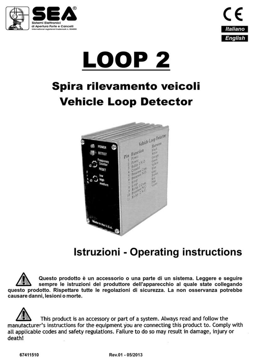
SEA LOOP 23105158 User manual

Sistemi Elettronici
di Apertura Porte e Cancelli
International registered trademark n. 804888
®
English
LOOP
VEHICLE LOOP DETECTOR
SEA S.p.A.
Zona industriale 64020 S.ATTO Teramo - (ITALY)
Tel. +39 0861 588341 r.a. Fax +39 0861 588344
www.seateam.com
Rev.00 - 03/2013
(23105158)
67411575

IMPORTANT:
This product is an accessory or part of a system. Always read and follow the manufacturer’s instructions for the
equipment before connecting this product. Comply with all applicable codes and safety regulations. Failure to do so
may result in damage, injury or death.
PRODUCT OVERVIEW
The SEA vehicle loop detector is compatible with most gate operators. The SEA may be used in Center, Safety and Exit
loop positions. The display feature makes set-up easy by displaying the optimum sensitivity setting required to detect a
vehicle positioned on the loop. Ten sensitivity settings allow for fine adjustment of detection level. A
PULSE/PRESENSE switch allows configuration of output relay for presence or one second pulse on entry operation.
Four frequency settings provide flexibility in preventing crosstalk in multi-loop applications.
Sistemi Elettronici
di Apertura Porte e Cancelli
International registered trademark n. 804888
®
English
SPECIFICATIONS
CAUTIONS AND WARNINGS
CE REQUIREMENT: Use Pre-formed loops with built-in surge suppression for CE compliance.
Connect shield on lead in wire to earth ground.
CE REQUIREMENT: Use CE rated power supply for CE compliance providing suppression as
specified by EN61000-4-5.
Not to be used in safety applications.
When more than one loop detector is used, set each one to a different frequency.
Refer to DIP switch diagram for frequency settings.
!
Sensitivity 10 levels, 0-9
Display Indicates optimum sensitivity level, 0-9 Diagnostic aid
Loop frequency 4 settings (low, med-low, med-hi, high)
Loop inductance 20...2000µH (Q factor > 5)
Grounded loop Isolation transformer allows operation with poor quality loops
Automatic tuning Detector tunes to loop on power-up and following frequency
count function
Environmental tracking Automatic compensation
Surge protection Loop circuitry protected by surge suppressors
Detect output COM, NO and NC contacts
Power / loop fault indicator Green LED
Detect / frequency count indicator Red LED
ASB (Automatic Sensitivity Boost) Increases sensitivity after initial detection to prevent dropout due to
high-bed vehicles
Relay operation Presence or one-second pulse on entry
Power 12VDC...24VDC, 24VAC (see Cautions and Warnings)
Operating Current 18 mA
Operating temperature -40°C...82°C 0...95% relative humidity
Dimensions (L x W x H) 76mm - 22mm - 70mm
Weight 68 g
Connector 7 position male, 5mm ctrs.
Rev.00 - 03/20132 67411575

Sistemi Elettronici
di Apertura Porte e Cancelli
International registered trademark n. 804888
®
English
OPERATION
Power up
Upon power up the detector initializes by automatically tuning to the loop. The green LED indicates that the detector is
powered and operational.
Frequency setting
The operating frequency of the loop is a function of the specific loop inductance and DIP switch settings 3-4. The
primary purpose of the frequency setting is to allow the installer the ability to set different operating frequencies for multi-
loop installations, recommended to prevent crosstalk/interference from adjacent loops. After changing the frequency
setting, press the Frequency Count switch to re-initialize the detector. To check the operating frequency of a loop refer
to the Frequency Count section. To determine whether crosstalk between adjacent loops is occurring, refer to the
Sensitivity Display section.
Sensitivity Display
The sensitivity display simplifies the installation process by displaying the sensitivity setting required to detect a vehicle
on the loop. To use this feature, observe the display while a vehicle is moving into position on the loop, note the number
displayed, then adjust the sensitivity setting (rotary switch) to the displayed position.
During normal operation, when a vehicle is not on the loop, the display is blank. The effects of crosstalk or other
interference can be observed on the display when the loop is vacant. Interference or crosstalk will cause the display to
indicate a level, typically 8 or 9. It may be necessary to observe the display for a minute or so to see this effect. Change
the frequency setting to prevent crosstalk.
Sensitivity setting
The 10-position rotary switch allows for precise adjustment of detection level. The sensitivity level increases from
position 0 thru 9 with position 0 being the lowest sensitivity. Typical applications require a setting of 3 or 4. The sensitivity
display simplifies the installation process by displaying the sensitivity setting required to detect a vehicle on the loop.
To use this feature, observe the display while a vehicle is moving into position on the loop, note the number displayed,
then adjust the sensitivity setting (rotary switch) to the displayed position.
Frequency Count / Reset
Press the Frequency Count switch and count the number of flashes on the red LED. Each flash represents 10kHz. To
help to prevent crosstalk when multiple detectors are used for adjacent loops, perform a frequency count on each
detector to confirm the operation frequencies are different. Following a frequency count cycle, the detector re-
initializes.
Automatic Sensitivity Boost
The Automatic Sensitivity boost causes the sensitivity to increase following initial detection. This feature is useful to
prevent dropout when detecting high-bed vehicles. The sensitivity returns to its normal setting after the vehicle exits the
loop. Decimal point on the display indicatesASB on.
Output Relay
The pulse/presence switch allows the output relay to be configured for presence or one-second pulse on entry
operation. When set to pulse operation, the display cycles through “P...U...L...S...E” repeatedly to indicate that the
detector is set for pulse operation. When set to presence, the output relay remains activated while the vehicle is present
on the loop.
Rev.00 - 03/2013 367411575

Sistemi Elettronici
di Apertura Porte e Cancelli
International registered trademark n. 804888
®
English
CONTROLS AND INDICATORS
FREQUENCY SETTINGS
AUTOMATIC SENSITIVITY BOOST
OUTPUT RELAY
SENSITIVITY SETTING
DETECT / FREQUENCY COUNT
POWER / LOOP FAULT INDICATOR
DISPLAY
FREQUENCY COUNT / RESET
DIP switch position
FREQUENCY 4 3
Low on on
Medium low off on
Medium high on off
High off off
DIP switch position 2
ASB enabled on
ASB off off
DIP switch position 1
Pulse on
Presence off
Position 0........9
Sensitivity Low.......high
Red LED
Presence detected on
No presence off
Frequency count flashing
Indicates sensitivity setting required to detect vehicle
Green LED
Normal operation on
Shorted loop 1 fast flash
Open loop 2 fast flashes
Abrupt change (>20%) 3 fast flashes
Previous loop fault 2 slow flashes
Press to start frequency count, re-initializes after count
Rev.00 - 03/20134 67411575

Sistemi Elettronici
di Apertura Porte e Cancelli
International registered trademark n. 804888
®
English
CONNECTIONS
Connector pin Description
1 Loop
2 Loop
3 Power + (12VDC¡¦24VDC, 24VAC)
4 Power - (12VDC¡¦24VDC, 24VAC)
5 Pulse/Presence relay Normally Open (NO)
6 Pulse/Presence relay Common (COM)
7 Pulse/Presence relay Normally Closed (NC)
Symptom Possible cause Solution
TROUBLESHOOTING
Check loop resistance on the
appropriate loop pins on the
control board connector, between
0.5 ohms and 5 ohms.
Green LED flashes Loop wire shorted or open
Check loop resistance on the
appropriate loop pins on the
control board connector.
Green LED flashes, 2 fast Loop was previously shorted
or open
1. Perform megger test from loop
lead to ground, should be >100
megohms
2. Check loop connections to
terminals
3. Check splices are properly
soldered and sealed against
moisture
4. Observe display, level indicated
on display indicates residual
frequency shift from vacant loop to
vehicle presence, press
Frequency Count switch to
reinitialize the detector
Detector remains in detect
after vehicle has left loop
1. Faulty loop
2. Poorly crimped terminals
3. Loose connections
1. Perform megger test from loop
lead to ground, should be >100
megohms
2. Check loop connections to
terminals
3. Check splices are properly
soldered and sealed against
moisture
4. Set adjacent loops to different
frequencies (see Frequency Setting)
Intermittent detection 1. Faulty loop
2. Poorly crimped terminals
3. Loose connections
4. Cross-talk between
adjacent loops
1. Check loop resistance on the
appropriate loop pins on the
control board connector, between .
5 ohms and 5 ohms.
2. With vehicle on loop, observe
display, set sensitivity to the
level indicated on the display
No detection 1. Loop wire shorted or open
2. Loop sensitivity set too
low
Rev.00 - 03/2013 567411575

Sistemi Elettronici
di Apertura Porte e Cancelli
International registered trademark n. 804888
®
English
Rev.00 - 03/2013
REALISATION OF THE SENSITIVE ELEMENT (FIG. 1)
The detectors are suitable for coils made up with an insulated copper wire with a cross-section of at least 1.5 sq.
mm. Preferably use twisted copper wires with at least 20 twists per metre to connect the detector to the coil.
Jointing in the coil wires and in the twisted cable is not recommended. If the wires used for the twisted cable are
especially long or in proximity to other power cables, shielding of said wires is recommended. Earthing of the shield
should only be made at the extremity of the detector.
Excepting special cases, the detection coils should be rectangular. Install with the longer sides placed at right angles in
the direction of vehicle movement. These sides should ideally be kept at a meter one from the other. Coil length is a
function of the width of the road surface to be monitored. A distance of no more than 300 mm is recommended between
the coil and each edge of the road surface. For coils running over a perimeter of more than ten metres two wire windings
are normally employed, while for coils with a lower perimeter three or more windings are required, and four windings are
required for coils with a perimeter below six metres.
All permanent coil components must be secured to the road surface in appropriate grooves made using masonry
cutting tools or the like. A cross-cut at a 45° inclination must be made at the circuit angles so as to prevent the risk of the
coil cable being damaged in proximity to the apex of the right angles.
Nominal groove length: 4 mm.
Nominal groove depth: 50 mm.
The coil-detector connection cable must also be laid in an appropriate groove running from one of the circuit angles
along the circuit perimeter to the road surface edge. To ensure wiring continuity between the coil and connection cable
allow for a long enough lead to reach as far as the detector before inserting the cable inside the coil groove. After laying
the required number of wire windings in the groove along the coil perimeter, route the wire towards the road edge
through the connection cable groove.
It is advisable that connection cable length not exceed 100 metres. As coil sensitivity diminishes proportionally to
connection cable length the latter should be kept as short as possible.
Coils are secured to road surface by means of a quick-drying compound containing epoxy resin or asphalt mastic
applied hot.
2
1.5 mm section cable
Cable width
Groove
depth
Fig. 1
0,3 m
max. 1 m
max. 5 m
0,3 m
At least 3 turns are recommended
At least 20 twists
Note:It is advisable to use an only piece of uninterrupted cable to forme the loop. Therefore, it is preferable to make a
preliminary of the cable length.
Ex. (Perimeter loop per twists) + distance of the module + 200 mm.
15 mm
25
mm
ORDERING INFORMATION
SEA Vehicle Loop Detector (Cod.23105158).
6 67411575

TERMS OF SALES
EFFICACY OF THE FOLLOWING TERMS OF SALE: the following general terms of sale shall be applied to all orders sent to SEA
S.p.A. All sales made by SEA to all costumers are made under the prescription of this terms of sales which are integral part of sale
contract and cancel and substitute all apposed clauses or specific negotiations present in order document received from the buyer.
GENERAL NOTICE The systems must be assembled exclusively with SEA components, unless specific agreements apply. Non-
compliance with the applicable safety standards (European Standards EM12453 – EM 12445) and with good installation practice
releases SEAfrom any responsibilities. SEAshall not be held responsible for any failure to execute a correct and safe installation under
the above mentioned standards.
1) PROPOSED ORDER The proposed order shall be accepted only prior SEA approval of it. By signing the proposed order, the Buyer
shall be bound to enter a purchase agreement, according to the specifications stated in the proposed order.
On the other hand, failure to notify the Buyer of said approval must not be construed as automatic acceptance on the part of SEA.
2) PERIOD OF THE OFFER The offer proposed by SEA or by its branch sales department shall be valid for 30 solar days, unless
otherwise notified.
3) PRICING The prices in the proposed order are quoted from the Price List which is valid on the date the order was issued. The
discounts granted by the branch sales department of SEA shall apply only prior to acceptance on the part of SEA. The prices are for
merchandise delivered ex-works from the SEA establishment in Teramo, not including VAT and special packaging. SEA reserves the
right to change at any time this price list, providing timely notice to the sales network. The special sales conditions with extra discount
on quantity basis (Qx, Qx1, Qx2, Qx3 formula) is reserved to official distributors under SEAmanagement written agreement.
4) PAYMENTS The accepted forms of payment are each time notified or approved by SEA. The interest rate on delay in payment shall
be 1.5% every month but anyway shall not be higher than the max. interest rate legally permitted.
5) DELIVERY Delivery shall take place, approximately and not peremptorily, within 30 working days from the date of receipt of the
order, unless otherwise notified. Transport of the goods sold shall be at Buyer’s cost and risk. SEA shall not bear the costs of delivery
giving the goods to the carrier, as chosen either by SEA or by the Buyer. Any loss and/or damage of the goods during transport, are at
Buyer’s cost.
6) COMPLAINTS Any complaints and/or claims shall be sent to SEA within 8 solar days from receipt of the goods, proved by adequate
supporting documents as to their truthfulness.
7) SUPPLY The concerning order will be accepted by SEA without any engagement and subordinately to the possibility to get it’s
supplies of raw material which is necessary for the production; Eventual completely or partially unsuccessful executions cannot be
reason for complains or reservations for damage. SEA supply is strictly limited to the goods of its manufacturing, not including
assembly, installation and testing. SEA, therefore, disclaims any responsibility for damage deriving, also to third parties, from non-
compliance of safety standards and good practice during installation and use of the purchased products.
8) WARRANTY The standard warranty period is 12 months. This warranty time can be extended by means of expedition of the
warranty coupon as follows:
SILVER: The mechanical components of the operators belonging to this line are guaranteed for 24 months from the date of
manufacturing written on the operator.
GOLD: The mechanical components of the operators belonging to this line are guaranteed for 36 months from the date of
manufacturing written on the operator.
PLATINUM: The mechanical components of the operators belonging to this line are guaranteed for 36 months from the date of
manufacturing written on the operator. The base warranty (36 months) will be extended for further 24 months (up to a total of 60
months) when it is acquired the certificate of warranty which will be filled in and sent to SEA S.p.A. The electronic devices and the
systems of command are guaranteed for 24 months from the date of manufacturing. In case of defective product, SEA undertakes to
replace free of charge or to repair the goods provided that they are returned to SEA repair centre. The definition of warranty status is by
unquestionable assessment of SEA. The replaced parts shall remain propriety of SEA. Binding upon the parties, the material held in
warranty by the Buyer, must be sent back to SEArepair centre with fees prepaid, and shall be dispatched by SEA with carriage forward.
The warranty shall not cover any required labour activities.
The recognized defects, whatever their nature, shall not produce any responsibility and/or damage claim on the part of the Buyer
against SEA. The guarantee is in no case recognized if changes are made to the goods, or in the case of improper use, or in the case of
tampering or improper assembly. Furthermore, the warranty shall not apply if SEA products are partly or completely coupled with non-
original mechanical and/or electronic components, and in particular, without a specific relevant authorization, and if the Buyer is not
making regular payments. The warranty shall not cover damage caused by transport, expendable material, faults due to non-
conformity with performance specifications of the products shown in the price list. No indemnification is granted during repairing and/or
replacing of the goods in warranty. SEA disclaims any responsibility for damage to objects and persons deriving from non-compliance
with safety standards, installation instructions or use of sold goods.
9) RESERVED DOMAIN Aclause of reserved domain applies to the sold goods; SEA shall decide autonomously whether to make use
of it or not, whereby the Buyer purchases propriety of the goods only after full payment of the latter.
10) COMPETENT COURT OF LAW In case of disputes arising from the application of the agreement, the competent court of law is the
tribunal of Teramo. SEA reserves the faculty to make technical changes to improve its own products, which are not in this price list at
any moment and without notice. SEA declines any responsibility due to possible mistakes contained inside the present price list
caused by printing and/or copying. The present price list cancels and substitutes the previous ones. The Buyer, according to the law
No. 196/2003 (privacy code) consents to put his personal data, deriving from the present contract, in SEAarchives and electronic files,
and he also gives his consent to their treatment for commercial and administrative purposes. Industrial ownership rights: once the
Buyer has recognized that SEA has the exclusive legal ownership of the registered SEA brand, he will commit himself to use it in a way
which does not reduce the value of these rights, he won’t also remove, replace or modify brands or any other particularity from the
products. Any kind of replication or use of SEA brand is forbidden as well as of any particularity on the products, unless preventive and
expressed authorization by SEA.
In accomplishment with art. 1341 of the Italian Civil Law it will be approved expressively clauses under numbers:
4) PAYMENTS - 8) GUARANTEE - 10) COMPETENT COURT OF LOW
English
Rev.00 - 03/2013 7
Sistemi Elettronici
di Apertura Porte e Cancelli
International registered trademark n. 804888
®
67411575

GENERAL NOTICE FOR THE INSTALLER AND THE USER
1. Read carefully these Instructions before beginning to install the product. Store these instructions for future
reference
2. Don’t waste product packaging materials and /or circuits.
3. This product was designed and built strictly for the use indicated in this documentation. Any other use, not expressly
indicated here, could compromise the good condition/operation of the product and/or be a source of danger. SEAS.p.A.
declines all liability caused by improper use or different use in respect to the intended one.
4. The mechanical parts must be comply with Directives: Machine Regulation 2006/42/CE and following adjustments),
Low Tension (2006/95/CE), electromgnetic Consistency (2004/108/CE) Installation must be done respecting
Directives: EN12453 and En12445.
5. Do not install the equipment in an explosive atmosphere.
6. SEA S.p.A. is not responsible for failure to observe Good Techniques in the construction of the locking elements to
motorize, or for any deformation that may occur during use.
7. Before attempting any job on the system, cut out electrical power and disconnect the batteries. Be sure that the
earthing system is perfectly constructed, and connect it metal parts of the lock.
8. Use of the indicator-light is recommended for every system, as well as a warning sign well-fixed to the frame
structure.
9. SEA S.p.A. declines all liability as concerns the automated system’s security and efficiency, if components used, are
not produced by SEAS.p.A..
10. For maintenance, strictly use original parts by SEA.
11. Do not modify in any way the components of the automated system.
12. The installer shall supply all information concerning system’s manual functioning in case of emergency, and shall
hand over to the user the warnings handbook supplied with the product.
13. Do not allow children or adults to stay near the product while it is operating. The application cannot be used by
children, by people with reduced physical, mental or sensorial capacity, or by people without experience or necessary
training. Keep remote controls or other pulse generators away from children, to prevent involuntary activation of the
system.
14. Transit through the leaves is allowed only when the gate is fully open.
15. The User must not attempt to repair or to take direct action on the system and must solely contact qualified SEA
personnel or SEAservice centers. User can apply only the manual function of emergency.
16. The power cables maximum length between the central engine and motors should not be greater than 10 m. Use
2
cables with 2,5 mm section. Use double insulation cable (cable sheath) to the immediate vicinity of the terminals, in
particular for the 230V cable. Keep an adequate distance (at least 2.5 mm in air), between the conductors in low voltage
(230V) and the conductors in low voltage safety (SELV) or use an appropriate sheath that provides extra insulation
having a thickness of 1 mm.
English
Rev.00 - 03/20138
Sistemi Elettronici
di Apertura Porte e Cancelli
International registered trademark n. 804888
®
67411575

Dichiarazione di conformità
Declaration of Conformity
Descrizione / Description Modello / Model Marca / Trademark
LOOP SPIRA MAGNETICA 23105158 SEA
23105158 SEA
La SEA S.p.A. dichiara che il prodotto sopra descritto è conforme alle seguenti norme:
SEA S.p.A. declares that the equipment described above conforms to the following Directives:
EN 61000-4-2:1995, including A1:1998 and A2:2001
Electrostatic discharge immunity Pass
EN 61000-4-3:2002 Radiated immunity Pass
EN 61000-4-4:2004 Fast transients/burst immunity Pass
EN 61000-4-5:1995, including A1:2001
Surge immunity Pass
EN 61000-4-6:1996, including A1:2001
Conducted immunity Pass
REF: EN 55011:2007 Limits and methods of measurement
COSTRUTTORE o RAPPRESENTANTE AUTORIZZATO:
MANUFACTURER or AUTHORISED REPRESENTATIVE:
SEAS.p.A.
DIREZIONE E STABILIMENTO:
Zona industriale 64020 S.ATTO Teramo - (ITALY)
Tel. +39 0861 588341 r.a. Fax +39 0861 588344
Http://www.seateam.com
I test sul prodotto sono stati effettuati in configurazione standard e in riferimento alle norme specifiche
per la sua classe d'utilizzo.
The products have been tested in standard configuration and with reference to the special norms
concerning the classe of use.
(Luogo, data di emissione)
(Place, date of issue)
Teramo, 22/03/2013
VEHICLE LOOP DETECTOR
Rev.00 - 03/2013 9
Sistemi Elettronici
di Apertura Porte e Cancelli
International registered trademark n. 804888
®
67411575

Questo articolo è stato prodotto seguendo rigide procedure
di lavorazione ed è stato testato singolarmente al fine di
garantire i più alti livelli qualitativi e la vostra soddisfazione.
Vi ringraziamo per aver scelto SEA.
This item has been produced following strict production
procedures and has been singularly tested for the highest
quality levels and for your complete satisfaction.
Thanks for choosing SEA.
Este articulo ha sido producido siguiendo rigidos
procedimientos de elaboracion y ha sido probando
singolarmente a fin de garantizar los mas altos inveles de
calidad y vuestra satisfaccion.
Le agradecemos por haber escogito SEA.
Cet article a été produit suivant des procédures d'usinage
strictes et il a singulièrement été testé afin de garantir
les plus hauts niveaux de qualité pour votre satisfaction.
Nous vous remercions d'avoir choisi SEA.


Sistemi Elettronici
di Apertura Porte e Cancelli
International registered trademark n. 804888
®
SEA S.p.A.
Zona industriale 64020 S.ATTO Teramo - (ITALY)
Tel. +39 0861 588341 r.a. Fax +39 0861 588344
www.seateam.com
Table of contents
Other SEA Security Sensor manuals
