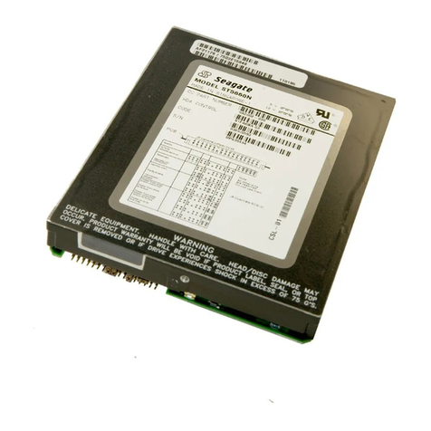
Seagate ST5660A User manual

. . . . . . . . . . . . . . . . . . . . . . . . . . . . . . . . . . . . .. . . . .
ST5660A
. . . . . . . . . . . . . . . . . . . . . . . . . . . . . . . . . . . . .. . . . .
AT Interface Drive
. . . . . . . . . . . . . . . . . . . . . . . . . . . . . . . . . . . . .. . . . .
. . . . . . . . . . . . . . . . . . . . . . . . . . . . . . . . . . . . .. . . . .
. . . . . . . . . . . . . . . . . . . . . . . . . . . . . . . . . . . . .. . . . .
Product Manual
. . . . . . . . . . . . . . . . . . . . . . . . . . . . . . . . . . . . .. . . . .


. . . . . . . . . . . . . . . . . . . . . . . . . . . . . . . . . . . . .. . . . .
ST5660A
. . . . . . . . . . . . . . . . . . . . . . . . . . . . . . . . . . . . .. . . . .
AT Interface Drive
. . . . . . . . . . . . . . . . . . . . . . . . . . . . . . . . . . . . .. . . . .
. . . . . . . . . . . . . . . . . . . . . . . . . . . . . . . . . . . . .. . . . .
. . . . . . . . . . . . . . . . . . . . . . . . . . . . . . . . . . . . .. . . . .
Product Manual
. . . . . . . . . . . . . . . . . . . . . . . . . . . . . . . . . . . . .. . . . .

© 1994 Seagate Technology, Inc. All rights reserved
Publication Number: 36242-001, Rev. A
March 1994
Seagate®, Seagate Technology®and the Seagate logo are registered
trademarks of SeagateTechnology,Inc. Otherproductnamesaretrade-
marks or registered trademarks of their owners.
Seagate reserves the right to change, without notice, product offerings
or specifications. No part of this publication may be reproduced in any
form without written permission from Seagate Technology, Inc.

Contents
1.0 Specifications . . . . . . . . . . . . . . . . . . . . . . . . . . 1
1.1 Formatted capacity . . . . . . . . . . . . . . . . . . . . . . 1
1.2 Functional specifications . . . . . . . . . . . . . . . . . . . 2
1.2.1 Seek time . . . . . . . . . . . . . . . . . . . . . . . . . 2
1.2.2 Multisegmented cache buffer . . . . . . . . . . . . . . . 3
1.3 Start/stop time . . . . . . . . . . . . . . . . . . . . . . . . . 3
1.4 Typical power-up and power-down sequence . . . . . . . . . 3
1.4.1 Power-up sequence . . . . . . . . . . . . . . . . . . . 3
1.4.2 Power-down sequence . . . . . . . . . . . . . . . . . . 4
1.4.3 Auto-park . . . . . . . . . . . . . . . . . . . . . . . . . 4
1.5 Reliability . . . . . . . . . . . . . . . . . . . . . . . . . . . 4
1.6 Physical dimensions . . . . . . . . . . . . . . . . . . . . . 4
1.7 Environmental specifications . . . . . . . . . . . . . . . . . 5
1.7.1 Ambient temperature . . . . . . . . . . . . . . . . . . . 5
1.7.2 Temperature gradient . . . . . . . . . . . . . . . . . . 5
1.7.3 Relative humidity . . . . . . . . . . . . . . . . . . . . . 5
1.7.4 Altitude . . . . . . . . . . . . . . . . . . . . . . . . . . 5
1.7.5 Acoustics . . . . . . . . . . . . . . . . . . . . . . . . . 5
1.8 Shock and vibration . . . . . . . . . . . . . . . . . . . . . . 6
1.9 DC power . . . . . . . . . . . . . . . . . . . . . . . . . . . 6
1.9.1 Input noise . . . . . . . . . . . . . . . . . . . . . . . . 6
1.9.2 Power management . . . . . . . . . . . . . . . . . . . 7
1.9.3 Power consumption . . . . . . . . . . . . . . . . . . . 9
1.10 Agency listings . . . . . . . . . . . . . . . . . . . . . . . 11
1.11 FCC verification . . . . . . . . . . . . . . . . . . . . . . 11
2.0 Configuring and mounting the drive . . . . . . . . . . . . . 13
2.1 Handling and static-discharge precautions . . . . . . . . . 13
2.2 I/O cable and connector . . . . . . . . . . . . . . . . . . 14
ST5660A Product Manual, Rev. A iii
2.3 Remote LED connection . . . . . . . . . . . . . . . . . . . 14
2.4 Jumpers . . . . . . . . . . . . . . . . . . . . . . . . . . . 15
2.4.1 Jumper sizes . . . . . . . . . . . . . . . . . . . . . . 15
2.4.2 Master/slave configuration . . . . . . . . . . . . . . . 15
2.5 Cable select option . . . . . . . . . . . . . . . . . . . . . . 17
2.6 Mounting the drive . . . . . . . . . . . . . . . . . . . . . . 18
3.0 AT interface . . . . . . . . . . . . . . . . . . . . . . . . . . 21
3.1 ST5660Acommands . . . . . . . . . . . . . . . . . . . . . 21
3.1.1 Identify Drive command (ECH) . . . . . . . . . . . . . 23
3.1.2 Set Features command (EFH) . . . . . . . . . . . . . 25
3.1.3 Sleep command (99H, E6H) . . . . . . . . . . . . . . . 25
3.2 Interface connector pin assignments . . . . . . . . . . . . 25
Appendix. Timing diagrams . . . . . . . . . . . . . . . . . . . . . 27
iv ST5660A Product Manual, Rev. A

Figures
Figure 1. Typical startup current profile . . . . . . . . . . . . . . . 10
Figure 2. AT interface connector . . . . . . . . . . . . . . . . . . 14
Figure 3. Configuration jumpers . . . . . . . . . . . . . . . . . . 16
Figure 4. Connecting cable-selected drives . . . . . . . . . . . . . 17
Figure 5. Mounting dimensions . . . . . . . . . . . . . . . . . . . 19
Figure 6. AT interface connector pin assignments . . . . . . . . . 26
Figure 7. Programmed I/O timing without IORDY . . . . . . . . . . 27
Figure 8. Programmed I/O timing with IORDY . . . . . . . . . . . 28
Figure 9. Multiword DMA timing . . . . . . . . . . . . . . . . . . . 29
ST5660A Product Manual, Rev. A v


1.0 Specifications
1.1 Formatted capacity
The drive was low-level formatted at the factory—you cannot low-level
format it.
You can operate the drive using many different logical configurations,
provided the number of sectors per track does not exceed 63. Three
possible configurations are shown below. The first two configurations
represent conventional CHS addressing as used on most DOS comput-
ers. The third configuration usesLBA addressing.
CHS CHS* LBA**
Cylinders 1,024 1,057 N/A
Heads 16 16 N/A
Sectors 63 63 N/A
Total sectors 1,032,192 1,065,456 1,066,184
Formatted capacity (Mbytes***) 528.48 545.3 545.8
*This is the default configuration. This configuration can only beused
in computers that are capable of addressing more than 1,024 cylin-
ders. Therefore, if your computer cannot address more than 1,024
cylinders, you must changethe configuration using the setup utility.
** This configuration can only be used in computers that support LBA
addressing.
***One megabyte equals one million bytes.
The drive was configured in translation mode at the factory. You can
verify the number of cylinders, sectors per track and headsand the total
numberof LBA sectors by using the Identify Drive (ECH) command.See
Section 3.1.1 for details about the Identify Drive command.
ST5660A Product Manual, Rev. A 1

1.2 Functional specifications
Interface AT (IDE)
Zone Bit Recording method RLL (1,7)
External data burst transfer rate
(Mbytes per sec) 11.1*
13**
Internal data transfer rate
(Mbits per sec) 27 to 48
Spindle speed (RPM) 4,500 ±0.5%
Cache size (Kbytes) 256
Read/write heads 4
Discs 2
Bytes per sector 512
Recording density, max (BPI) 68,000
Track density (TPI) 3,309
*This is the external transfer rate using PIO mode 3 timing.
** This is the external transfer rate using multiwordDMA mode 1 timing.
1.2.1 Seek time
Seek time is measured under nominal conditions of temperature and
voltagewiththe drive mountedhorizontally.Seektimeis atruestatistical
average of at least 5,000 seeks.
Track-to-track seek timeis the averageof all possible single-track seeks
in bothdirections.Averageseek timeis measuredby executingseeks in
both directions between random cylinders. Full-stroke seek time is half
the time needed to seek from track 0 to the maximum track and back to
track 0.
Host overhead varies between systems and cannot be specified. Drive
internal overhead is measured by issuing a no-motion seek and is
typically less than 0.5 msec.
Track-to-track
seek time Average/Typ
seek time Full-stroke seek
time Average
latency
3.5 msec typ
4.0 msec max 12.0 msec read
14.0 msec write 25.0 msec max 6.67 msec
2 ST5660A Product Manual, Rev. A

1.2.2 Multisegmented cache buffer
The drive uses the 256-Kbyte, multisegmented cache buffer to improve
performance by eliminating access times under certain conditions.
Readlook-ahead. The drive uses the read segments to store additional
logical sectors, after the last requested sector, into a buffer before the
additional sectors are requested by the computer. The cache buffer
storesdata from the start of a read until the buffer segment is full, or until
another command is received from the computer.
Write immediate. The drive uses the write segment to store write
commands and data. After the drive receives all the data for the com-
mand, it issues a write complete. Then, the drive writes the data to the
disc.
Write merging. The drive accepts contiguous write commands and
executes them as one command.
Write caching. The last datawritten by the driveis retainedin the buffer
for use by future reads.
1.3 Start/stop time
Within 20 seconds after DC power is applied, the drive is ready. Within
15 seconds after DC power is removed, the drive spindle stops rotating.
1.4 Typical power-up and power-down sequence
The typical power-up and power-down sequencesassist you in evaluat-
ing the drive’s performance; they are not performance specifications.
1.4.1 Power-up sequence
1. Power is applied to the drive.
2. When poweris applied, the LED is on for about 1 second.
3. The spindle motor reaches operating speed in about 4 seconds.
4. The magnetic actuator lock releases the actuator.
5. The drive performs velocity adjustment seeks.
6. The heads are positioned over track 0 and the drive is ready.
ST5660A Product Manual, Rev. A 3

1.4.2 Power-down sequence
Caution. Donot move the driveuntil the motor hascome to a complete
stop.
1. The poweris turned off.
2. Within 3 seconds, the motor begins to spin down.
3. The heads automatically move to the shipping zone, which is inside
the maximum data cylinder.
4. The magnetic actuator locks the arm with the heads over the landing
zone. This completesthe power-down sequence.
1.4.3 Auto-park
Upon power-down, the heads automatically move to the shipping zone.
The heads park inside the maximum data cylinder. When power is
applied, the heads recalibrate to track 0.
1.5 Reliability
Readerrorratesaremeasuredwithautomaticretriesanddatacorrection
with ECC enabled and all flaws re-allocated. The mean time between
failures (MTBF) is measured at nominal power at sea level and at an
ambient temperature of 40°C.
Nonrecoverable read errors 1 per 1013 bits transferred
Seek errors 1 per 107physical seeks
MTBF 300,000 power-on hours
Service life 5 years
1.6 Physical dimensions
The mounting dimensions are shown in Figure 5 on page 19.
Height, max 0.748 inches (19 mm)
Width, max 4.00 inches(101.6 mm)
Depth, max 5.00 inches (127 mm)
Weight 1.0 lb (0.45 Kg)
4 ST5660A Product Manual, Rev. A

1.7 Environmental specifications
1.7.1 Ambient temperature
Operating 5°C to 55°C (41°F to 131°F)
Nonoperating –40°C to 70°C (–40°F to 158°F)
1.7.2 Temperature gradient
Operating 20°C per hour (36°F per hour)
Nonoperating 30°C per hour (54°F per hour)
1.7.3 Relative humidity
Operating 8% to 80%noncondensing
Maximum wet bulb 26°C (79°F)
Maximum operating
gradient 10% per hour
Nonoperating 5% to 95%noncondensing
Maximum wet bulb 26°C (79°F)
1.7.4 Altitude
Operating –1,000 ft to 10,000 ft (–305 m to 3,048 m)
Nonoperating –1,000 ft to 40,000 ft (–305 m to 12,192 m)
1.7.5 Acoustics
Sound pressure is measured from 1 meter above the drive top cover at
idle.
Sound pressure, typ (dBA) 26
Sound pressure, max (dBA) 29
ST5660A Product Manual, Rev. A 5

1.8 Shock and vibration
Allshock and vibration specificationsassumethat the inputs are measured
at the drive mounting screws. Shock measurements are based on an
11-msec, half sine wave shock pulse, not to be repeated more than twice
persecond.
During normal operating shock and vibration, there is no physical dam-
age to the drive or performance degradation.
During abnormal operating shock and vibration, there is no physical
damageto the drive, althoughperformancemay be degradedduringthe
shockorvibrationepisode.Whennormaloperatingshocklevelsresume,
the drive meets its performance specifications.
During nonoperating shock and vibration, the read/write heads are
positioned in the shipping zone.
Normal
operating Abnormal
operating Nonoperating
Shock 2 Gs 10 Gs 75 Gs
5–22 Hz vibration 0.020-inch
displacement 0.030-inch
displacement 0.160-inch
displacement
22–400 Hz vibration 0.50 Gs 0.75 Gs 4.00 Gs
1.9 DC power
Except duringthe write procedure, you can turn off and turn on power to
the drive in any sequence without losing data or damaging the drive. If
you turn off the power during a write procedure, you may lose the data
currently being written.
1.9.1 Input noise
+5V +12V
Voltage tolerance
(including noise) ±5% ±5%
Input noise frequency
(max) 25 MHz 25 MHz
Input noise
(max, peak-to-peak) 100 mV 240 mV
6 ST5660A Product Manual, Rev. A

1.9.2 Power management
This drive provides and uses power-management modes which reduce
power consumption. The level of drive activity for each power-manage-
ment mode is described below.
You can customize the power-management modes using the AT inter-
face commands that control the power modes. These commands are
described in the
Seagate ATA Interface Reference Manual
, publication
number 36111-
xxx
.
Note. If you install the ST5660Aas a slavewith a master drivethat does
not support power management (for example, a Seagate
ST1239A drive), do not send power-management commands to
the ST5660A.
1.9.2.11.9.2.1 Power-management modes
The drive supports the following power-management modes:
•Spinup. The drivebringsthe spindleanddiscs up to operating speed.
Power in this mode is defined as the average power during the first
10 seconds of spinup. The drive enters this mode during startup and
from the Standby mode.
•Seeking. The drive moves the read/write heads to a specificlocation
on the disc surface in preparation for reading from or writing to the
disc. Read/write electronics are powereddown andservo electronics
are active. The power measured during this mode is the average
power while executing random seeks with a 2-revolution (26.6 msec)
dwell between Seek commands.
•Read/write. The drive reads from or writes to the disc. Read/write
electronics are active and the servo is on track. The drive enters this
mode from the Idle mode.
•Idle. The heads are parked in the shipping zone. The spindle is
spinningandthe cachebufferremainsenabled,andthe driveaccepts
all commands and returns to the Seekingor Read/write modes when
it receives a command that requires disc access.
•Standby. The spindle is stopped,the headsare parked in the landing
zone, the actuator is latched, and some of the drive electronics are
powereddown. The drivesetsa status flagindicating to the computer
thatitisreadytoaccessthedisc.Whenthedrivereceivesacommand
that does not require disc access, the drive remains in the Standby
mode.Whenthedrivereceivesacommandthatrequiresdiscaccess,
it spins up and performs the command.
ST5660A Product Manual, Rev. A 7

1.9.2.2 Idle and Standby modes
The drive can enterthe Idle orStandbymodesby either of two methods:
•The computer sends either the Idle command, the Idle Immediate
command, the Standby command or the Standby Immediate com-
mand.
•The idle timer or the standby timer counts down to zero.
At power-on,the standby timer is disabled. Also at power-on,the drive
sets theidle timerso that thedrive entersthe Idle modeafter 25 seconds
of inactivity. You can set the timer delays using the system setup utility.
During each read, write or seek, the drive reinitializes the idle timer and
begins counting down from the specified delay to zero.
If the idle timer reaches zero before the drive is commanded to read,
write or seek, the drive switches to the Idle mode. Then, if the standby
timer is enabled, the standby timer begins counting down. After the
standbytimer has finishedcounting down,the drive switches to Standby
mode. To set the idle and standby timers, refer to the Idle command in
the
Seagate ATA Interface Reference Manual
, publication num-
ber 36111-
xxx
.
While in either Idle mode or Standby mode, the drive accepts all com-
mands and returns to the Seeking or Read/write modes whenever disc
access is necessary.
8 ST5660A Product Manual, Rev. A

1.9.3 Power consumption
In the table below, the values apply at the drive power connector. Current
wasmeasuredwithanRMSDCammeteraftera10-minutewarm-upperiod.
Spinup Seeking Read/
Write Idle Standby
Current at +12V
Amps peak 1.2 — — — —
RMS amps typ — 0.354 0.208 0.116 0.012
Watts typ — 4.25 2.5 1.394 0.144
Current at +5V
RMS amps typ — 0.35 0.4 0.221 0.221
Watts typ — 1.75 2 1.106 1.106
Power
Total watts typ — 6.00 4.5 2.50 1.25
ST5660A Product Manual, Rev. A 9

The startup current profile of each drive is unique. A typical startup
current profile is shown in Figure 1.
T1 Power is applied to the drive.
T2 After a delay, the startup current is applied and the spindle
begins to turn.
T3 The accelerating current is applied, causing the spindle speed
to increase.
T4 The spindle speed is close to the final correct value. The drive
begins to lock in speed-control circuits.
T5 The magnetic arm lock releases the arm.
T6 The final speed-control lock is achieved.
T7 The heads are positioned over track 0 and the drive is ready.
0
0
0.2
0.4
0.6
0.8
1.0
1.2
1
T1
T2
T3
T4 T5
T6
T7
23456789
Amps
Seconds
Figure 1. Typical startup current profile
10 ST5660A Product Manual, Rev. A

1.10 Agency listings
This drive is listed by agencies as follows:
•Recognized in accordance with UL 478 andUL 1950
•Certified to CSA C22.2 No. 220-M1986 and CSA C22.2 No. 950
•Certified to VDE 0805/05.90 and EN 60950/1.88 as tested by VDE
1.11 FCC verification
The ST5660A drive is intendedto be contained solely withina personal
computer or similar enclosure (not attached to an external device). As
such, a drive is considered to be a subassembly even when individually
marketed to the customer. As a subassembly, no Federal Communica-
tions Commission authorization, verification or certification of the device
is required.
Seagate Technology, Inc. has tested these drives in an enclosure as
described above to ensure thatthe totalassembly (enclosure,disc drive,
motherboard, power supply, etc.) does comply with the limits for a
Class B computing device, pursuant to Subpart J of Part 15 of the FCC
rules. Operation with noncertified assemblies islikely to resultin interfer-
ence to radio andtelevision reception.
Radioandtelevisioninterference.Thisequipmentgeneratesanduses
radiofrequencyenergyand, if notinstalledand usedin strictaccordance
withthemanufacturer’sinstructions,maycauseinterferencetoradioand
television reception.
This equipment is designed to provide reasonable protection against
such interference in a residential installation. However, there is no
guarantee thatinterferencewillnotoccurinaparticularinstallation.Ifthis
equipment does cause interference to radio or television, which can be
determined by turning the equipment on and off, you are encouraged to
try one or more of the following corrective measures:
•Reorient the receiving antenna.
•Move the deviceto one side or the other of the radio orTV.
•Move the devicefarther away from the radio or TV.
•Plug the equipment into a different outlet so that the receiver and
computer are on different branch outlets.
ST5660A Product Manual, Rev. A 11

Ifnecessary,youshouldconsultyourdealeroranexperiencedradio/tele-
vision technician for additional suggestions. You may find helpful the
followingbookletpreparedbytheFederalCommunicationsCommission:
How to Identify and Resolve Radio-Television Interference Problems.
This booklet is available from the Superintendent of Documents, US
GovernmentPrintingOffice,Washington,DC20402.Refertopublication
number 004-000-00345-4.
Note. This digital apparatus does not exceed the Class B limits for radio
noise emissionsfrom computer equipment as set out in the radio
interference regulations of the Canadian Department of commu-
nications.
Le présent appareil numérique n′émet pas de bruits radioélectri-
ques dépassant les limites applicables aux appareils numériques
de Classe B prescrites dans le règlement sur le brouillage ra-
dioélectrique édicté par le Ministère des Communications du
Canada.
Sicherheitsanleitung
1. Das Gerrät ist ein Einbaugerät, das für eine maximale Umegebung-
stemperatur von 55°C vorgesehen ist.
2. Zur Befestigung des Laufwerks werden 4 Schrauben 6-32 UNC-2A
benötigt. Bei seitlicher Befestigung darf die maximale Länge der
Schrauben im Chassis nicht mehr als 5,08 mm und bei Befestigung
an der Unterseite nicht mehr als 5,08 mm betragen.
3. Als Versorgungsspannugen werden benötigt:
+5V ± 5% 0,65A
+12V ± 5% 0,45A (1,9A fur ca. 10 Sek. fur ±10%)
4. Die Versorgungsspannung muβSELV entsprechen.
5. AlleArbeitendürfennurvonausgebildetemServicepersonaldurchge-
führt werden.
6. DerEinbaudes DrivesmuβdenAnforderungen gemäβDIN IEC950V
DC 0805/05.90 entsprechen.
12 ST5660A Product Manual, Rev. A
Other manuals for ST5660A
1
Table of contents
Other Seagate DC Drive manuals

Seagate
Seagate ST9655 Series User manual

Seagate
Seagate ST3780A User manual

Seagate
Seagate Decathlon 850 User manual

Seagate
Seagate Medalist 630xe User manual

Seagate
Seagate ST500VM000 User manual

Seagate
Seagate MEDALIST 1270 User manual

Seagate
Seagate STT20000N User manual

Seagate
Seagate ST3285N User manual

Seagate
Seagate ST317221A User manual

Seagate
Seagate Exos 512N User manual