SEAGUARD Digital Corrosion Tester PRO User manual

03MAN00021 V2 139.7*215.9mm
USER MANUAL
DIGITAL CORROSION TESTER
PROFESSIONAL MODEL
USER MANUAL
SEAGUARD DIGITAL CORROSION TESTER
PROFESSIONAL MODEL
© 2017 Canada Metal (Pacic) Ltd. All rights reserved.
The information contained in this document is the sole property of Seaguard
International – a division of Canada Metal (Pacic) Ltd. Any reproduction
in part or whole without the written permission of Seaguard International
is prohibited. Seaguard International will not be liable for errors contained
herein or for incidental or consequential damages in connection with the
furnishing, performance, or use of this document. The information contained
in this manual is subject to change without notice.
This product complies with EU directives.
Danger
• Please do not use or store this product near explosive materials, strong
magnetic elds, or a combustible gas environment, otherwise it may cause
a re or explosion.
• To avoid being shocked, do not use this product when the tested object
has electrical power.
Warning
• Please do not repair, dismantle, or modify this product by yourself.
• If any abnormal situation occurs, such as smoke or abnormal noise, stop
using this product immediately.
Note
• If do not use this product for a long period, take out the batteries.
2

Table of Contents
1. Introduction........................................................................4
2. Operation...........................................................................5
2.1 Test Setup........................................................................5
2.2 Pro Model –Features........................................................5
2.3 Pro Model – Operation Screens.......................................5
2.3.1 Turning on the tester.....................................................5
2.3.2 Making selections in the tester screens........................6
2.3.3 Using the Selection Window..........................................6
2.3.4 Choosing the boat material...........................................6
2.3.5 Change the potential limit..............................................6
2.3.6 Taking measurements...................................................7
2.3.7 Reviewing saved data...................................................7
2.3.8 Clearing all the saved data...........................................8
2.3.9 Resetting to factory settings..........................................8
3. How to Connect and Measure...............................................8
3.1 General.............................................................................8
3.2 Sterndrive.........................................................................9
3.3 Inboard.............................................................................9
3.4 Outboard...........................................................................9
3.5 Others...............................................................................9
4. Maintenance.......................................................................9
5. Troubleshooting................................................................10
6. Specifications...................................................................10
7. For more information........................................................10
3

1. Introduction
This manual gives instructions for operating the Seaguard Digital
Corrosion Tester to test boats and other marine structures in
seawater. The professional model is designed to be used by
marina operators, shipyard workers and service technicians with
silver / silver chloride reference cell (SSC).
Measuring corrosion
Vessels in seawater produce galvanic reactions just like an electric
battery does. Electrical current will ow through the hull when the
hull contains different metals. This happens even in wooden hulls
with motors attached. The most active metal discharges electrical
current to the other metal, cycling the current back through the
seawater. The most active metal becomes corroded.
If a metal part is greater than 0.2 volts negative to its natural
potential, it will not corrode. If the part is positive to its natural
potential then we know that it is connected to a different type of
metal and it will cause corrosion.
One of the most effective protection methods is to add sacricial
electrodes called anodes to make the hull become a cathode,
where the current ows from one to the other.
To measure the actual corrosion process we measure the
electrical potential of the hull. If the voltage reading is too high, it
means the hull is not protected. If the voltage is too low, we say it
is “over-protected.” Over-protection will cause the hull coating to
lose its bond to the hull and peel off (“disbondment”). So checking
the electrical potential is very important.
The Seaguard Digital Corrosion Tester is a high-impedance
voltage meter with a reference cell. The tester is specially designed
to check the electrical potential of the hull at different locations on
the hull while the boat is in seawater. Each reading is color coded
to indicate whether the boat is protected (PASS, green), under-
protected (FAIL, red), or overprotected (OVER, yellow).
The following parts are included:
• Corrosion tester handheld device
• Ag/AgCl reference cell (SSC) with 20 feet long cable (Pro Model)
• Test probe with alligator clip and 6 feet long cable
4
2.2 Pro Model - Features
2. Operation
WARNING! – The corrosion tester is a sensitive instrument
used to measure the electrical potential of a boat hull or
submerged structures. Please operate it according to these
instructions.
2.1 Test Setup
Open the battery cover and install provided 3 AAA batteries.
Note the orientation of the batteries.
Connect the reference cell.
Connect the alligator test probe. You are ready to use.
5
78
6
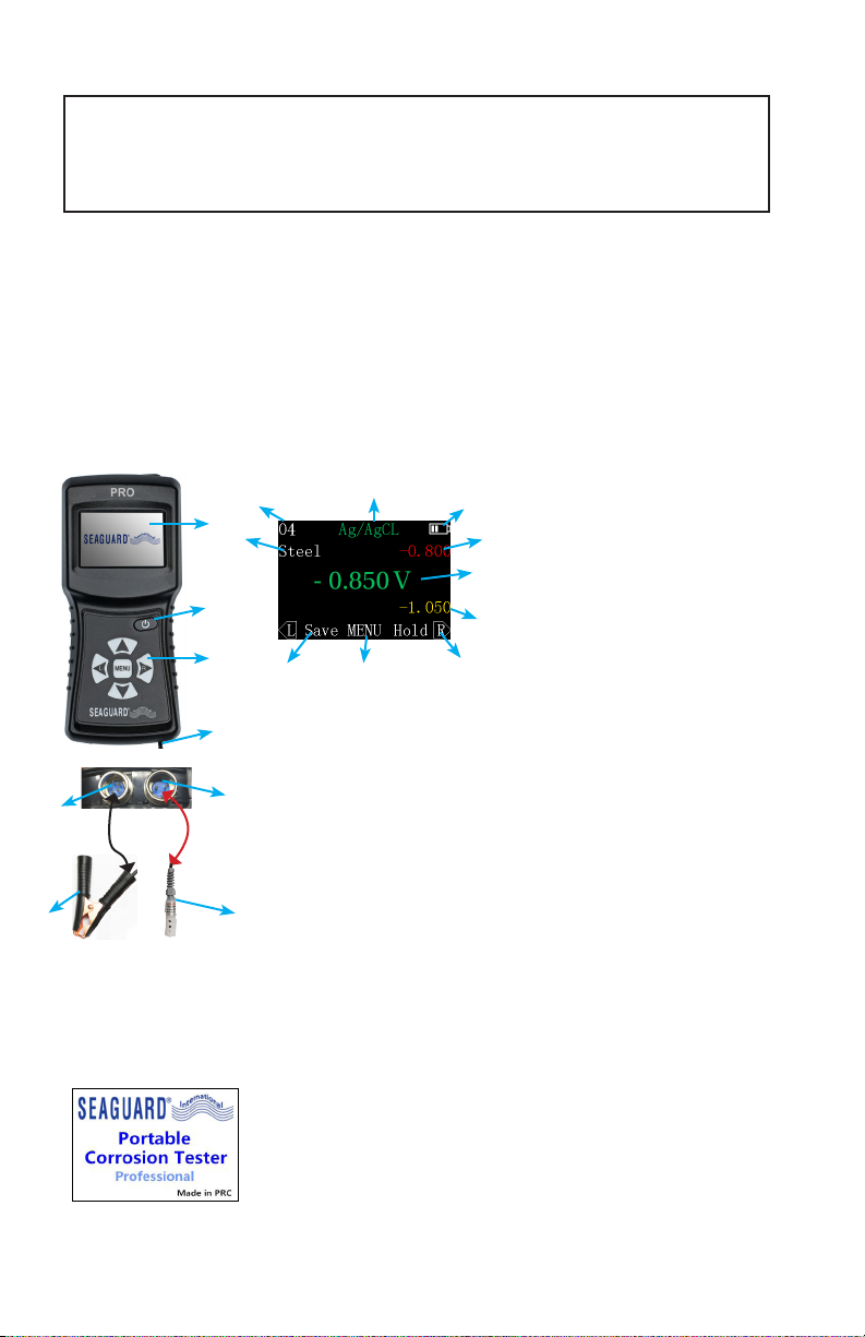
1. Display screen
2. Power button
3. Key pad
4. Lanyard
5. Port for reference cell
6. Port for alligator clip
7. Alligator clip
8. Ag/AgCl reference cell
9. Selected material indicator
10. Number of stored reading
11. Type of reference cell
12. Power indicator
13. Upper limit
14. Corrosion protection value
15. Lower limit
16. Right function indicator
17. MENU/Save/Back/Update(Upd) indicator
18. Left function indicator
11 12
13
14
15
16
17
18
9
10
1
2
3
4
Figure 1 Pro Model
2.3.1. Turning on the tester
Press the power button. The tester will display
the Welcome Screen (Figure 2) and then the
Corrosion Measuring Screen (see Figure 6).
If the battery power is too low, the tester will not
turn on.
Figure 2 Welcome
screen
2.3 Pro Model – Operation Screens
5
2.3.3. Using the Selection Window
From the Potential Measuring Screen, press the
button to display the Main Menu Screen
(Figure 4).
From the Menu Screen you can review stored
measurement data, modify the potential limit
settings for a material type, clear your stored
data, and reset the tester to factory settings.
2.3.4. Choosing the boat material
Before measuring, rst identify the material of the hull or xture
that you want to measure. From the Corrosion Measuring
Screen, press Up/Down keys to select the right material. The
material options are Steel alloy, Aluminum alloy, Copper alloy
and others.
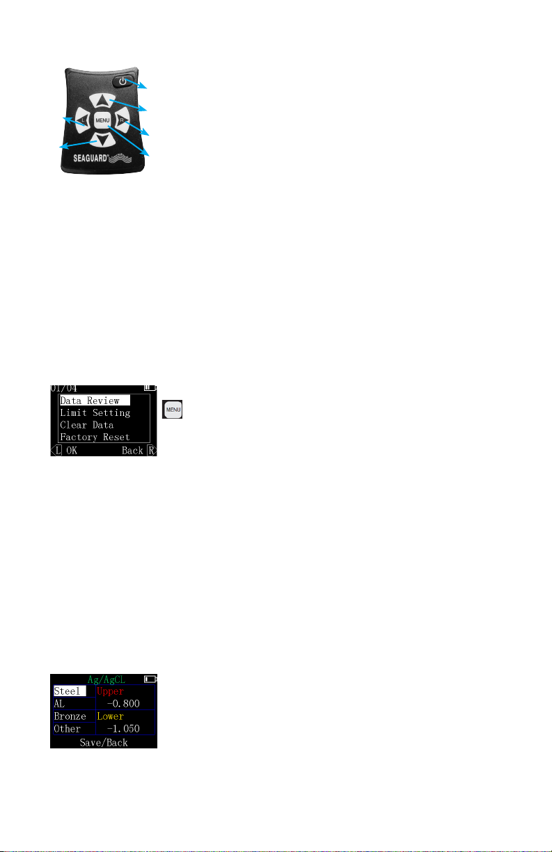
2.3.2 Making selections in the tester screens
Use the hand buttons to perform all functions
of the tester.
Using the selection buttons
1. Power button
2. Move up, or increase number
3. Right “soft key” on the display
4. Go to the Selection Screen, or middle soft
key on the display
5. Left “soft key” on the display
6. Move down, or decrease number
To make selections, press the buttons on the tester (Figure
3). The words displayed along the bottom of each screen
are “soft keys” that represent the functions of the left key, the
central menu key, and the right key. The functions will change
depending on which screen you are viewing. For examples,
see the screen images below.
1
2
3
4
6
5
Figure 3 e keypad
Figure 4 e Menu
Screen
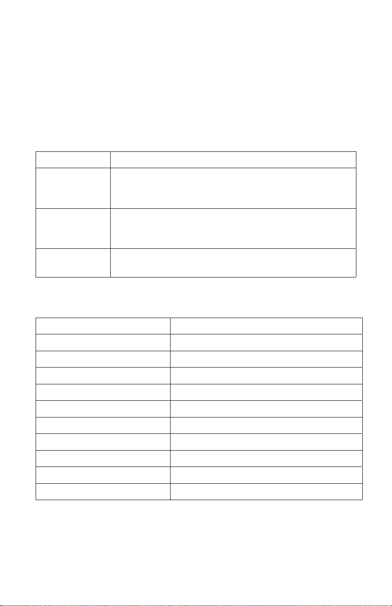
2.3.5. Change the potential limit
For advance user, you can customize all potential
limits for different materials in Limit Setting Screen.
To customize the Limit Settings for uncommon
materials:
Figure 5 Limit Setting Screen
6

1). Choose “Others” material.
2). Select the Upper or Lower setting value for that material.
3). Press or to increase or decrease the value.
4). Save the new Limit Settings. You will be taken back to the
Measuring Screen.
In the same way, you may change the values for steel, aluminum,
and bronze as well, based on your knowledge about corrosion.
For your reference, Table 1 lists the potential factory setting values
for protected, under-protected, and over-protected conditions for
each type of boat material.
Table 1 - Potential Limit Factory Settings for the Seaguard
Digital Corrosion Tester (Ag/AgCl reference cell - SSC)
Hull Material Under
protection Safe Protected Over
protection
Steel alloys > -0.800V -0.800V to -1.050V < -1.050V
Aluminum alloys > -0.900V -0.900V to -1.100V < -1.100V
Copper alloys > -0.500V -0.500V to -0.700V < -0.700V
Others > -0.500V -0.500V to -0.700V < -0.700V
The “<” symbol means “less than” the given limit, in the negative
direction. The “>” symbol means “greater than” the given limit, in
the positive direction. The default setting is steel.
2.3.6. Taking measurements
Your Potential readings are displayed directly on
the Corrosion Measuring Screen (Figure 6).
To save the current measurement value, press the
left button (Save). A window will appear for you to
conrm that you do want to save, yes or no.
Figure 6 Corrosion
Measuring Screen
Important – For correct interpretation, note the polarity of the
voltage reading (+ or -).
2.3.7. Reviewing saved data
The example of the Data Review Screen (Figure 7) shows
7

readings for over-protected steel (in yellow),
measured relative to the corrosion tester’s Ag/
AgCL reference cell (SSC). To delete a saved
measurement, select it using the Up/Down keys,
then press the left key (Del).
To display a highlighted measurement in the
Measuring Screen, press the Menu key “Upd”. As
shown in Figure 8, you can now view the static
saved measurement along with the upper and
lower limits, to compare them. To return to the Data
Review Screen press the MENU key (Back).
2.3.8. Clearing all the saved data
From the Menu Screen (Figure 4), choose Clear Data. A window
will pop up for you to conrm that you do want to save, yes or no.
2.3.9. Resetting to factory settings
From the Menu Screen (Figure 4), choose Factory Reset. A
window will pop up for you to conrm that you do want to reset the
data, yes or no.
Figure 7 Saved Data
Figure 8 Update
Saved Data
3. How to Connect and Measure
WARNING! - Do not put the reference cell or test probe
into water that is contaminated with oil, diesel, gas, or
pollutants. This can cause contamination of the reference
cell and erroneous readings.
3.1 General
Lower the reference cell into the water so that it is at least a foot
below the water surface, near to the boat. If there is wave action,
lower the reference cell deeper.
Secure the test lead using alligator clip to a point above water on
the metal being tested.
Make an effective connection. The metal surface will often be
covered by paint, dirt, oil, or rust. Make sure that the probe has
effective electrical contact directly with the metal. Probe several
times in different locations on the same material. If good contacts
are made, the readings will be stable and very similar in the
different locations. When taking measurements from a xture
attached to the hull, make sure that the xture has been properly
bonded. Search for a contact point until the measurement is
stable.
8

CLIP TO BOLT
HOLDING ENGINE
3.4 Outboard
3.5 Others
Any other structure that is steel, aluminum or copper which
is in water can be measured.
CLIP TO BOLT
ON OUTDRIVE
CLIP TO GROUND STRAP
OR TO COPPER WIRE
CONNECTING ITEMS SHOWN
3.2 Sterndrive 3.3 Inboard
9
4. Maintenance
Ag/AgCl reference cell (SSC) is maintenance free.
After using the tester:
1). Rinse the reference cell and test probe in fresh water.
2). Dry all parts after use and keep them in the box.
3). Store in a dry, safe place.
5. Troubleshooting
Problem Possible solution
No display Check that the test probe lead and reference
cell are plugged into the correct place. The
battery is dead. Replace the battery.
Reading is
inaccurate
Check the wire of the reference cell. Replace
it if there is any damage. Clean the surface of
Zinc reference cell using ne sand paper.
Any damage Contact Seaguard International for
replacement.
6. Specications
Measurement range -2.500 to +2.500 volts
Measurement accuracy 0.5%
AD resolution 16 bits
Input impedance >108 Ω
Display TFT LCD 1.8”, 320x220
Power 3 AAA Batteries
Auto shutdown No button action for 2.5 minutes
Manual shutdown Press power button >2 seconds
Data stored Maximum 50 measurement values
Working temperature -10°C to 50°C
Dimensions 142 mm x 63 mm x 32 mm
7. For more information
For more information, please check out our website
seaguardinternational.com
10
Table of contents
Popular Test Equipment manuals by other brands

Apera Instruments
Apera Instruments GroStar GS2 user manual

Maurer Elektromaschinen
Maurer Elektromaschinen Captest 1225 V2 Operation manual

Teledyne
Teledyne HDO8000A Getting started guide

Keysight
Keysight U1610A user guide

Klein Tools
Klein Tools RT210 user manual

Lifeloc
Lifeloc Phoenix 6.0BT Operation manual


