EMTEST variac-NX 1-260-16 User manual

Operating
manual
Motor driven AC source
variac-NX 1-260-16 0 - 260V 16 A
variac-NX 1-260-32 0 - 260V 32 A
variac-NX 1-280-16 0 - 280V 16 A
The motorized AC variacs of the series NX are suitable for volt-
age dips and voltage variation test.
The the internal voltage control compensates automatically volt-
age variations on the mains supply for the tapped output
voltage.
EN/IEC 61000-4-11
EN 61000-6-1
EN 61000-6-2
Version:
V1.05 / 18.03.2021
The benchmark for emc
Replaces:
V1.04 / 17.03.2021
Filename:
UserManual-variac-NX 1-260-xx-E-V1.05.doc
Printdate:
18.03.21


AMETEK CTS variac-NX 1 series
Operating manual V 1.05 3 / 23
Contents
1. Standards for testing with variac-NX series .................................................................4
1.1. Models and options ............................................................................................................................4
2. Operating Functions .......................................................................................................5
2.1. Operating elements on front and rear side variac-NX 1-260-16 ........................................................5
3. Putting into Operation.....................................................................................................6
3.1. Inspection ...........................................................................................................................................6
3.2. Supply voltage....................................................................................................................................6
3.3. Main socket and plug..........................................................................................................................6
3.4. Safety aspects....................................................................................................................................6
3.5. Switch on condition.............................................................................................................................6
3.6. Remote control voltage.......................................................................................................................6
3.7. Variac-NX 1-260-xx configuration in the generator setup menu ........................................................7
3.8. Output plugs .......................................................................................................................................7
4. Variac................................................................................................................................8
4.1. General...............................................................................................................................................8
4.2. Function description ...........................................................................................................................8
4.3. Overload.............................................................................................................................................8
5. Controller type TVR 6500................................................................................................9
5.1. General...............................................................................................................................................9
5.2. Function description TVR 6500..........................................................................................................9
5.3. General functions of TVR 6500........................................................................................................10
5.4. Wiring diagram TVR 6500 ................................................................................................................11
6. Maintenance of Air cooled variable Transformers .....................................................12
7. Application and setup...................................................................................................13
7.1. Application for IEC 61000-4-11..........................................................................................................13
7.1.1. Test setup for dips and interruption..................................................................................................14
7.1.2. Test setup for dips and interruption..................................................................................................14
8. Technical data ...............................................................................................................15
8.1. Technical data variac-NX 1-2xx-yy family..........................................................................................15
8.2. Environmental conditions .................................................................................................................15
9. Model design .................................................................................................................16
9.1. variac-NX 1-260-16 and variac NX 1-280-16...................................................................................16
9.1.1. Diagram variac NX 1-2x0-16............................................................................................................17
9.2. variac-NX 1-260-32 ..........................................................................................................................18
9.2.1. Diagram variac NX 1-260-32............................................................................................................19
10. Appendix........................................................................................................................20
10.1. Declaration of conformity..................................................................................................................20
10.1.1. Diagram variac NX 1-260-16............................................................................................................21
10.1.2. Diagram variac NX 1-260-32............................................................................................................22
10.1.3. Diagram variac NX 1-280-16............................................................................................................23

AMETEK CTS variac-NX 1 series
Operating manual V 1.05 4 / 23
1.
Standards for testing with variac-NX series
The AC motorized tramsformers of the series variac-NX are used for the following standard tests:
- IEC 61000-4-11
Testing and measurement techniques - Voltage dips, short interruptions and
voltage variations immunity tests
- IEC 61000-4-8
Testing and measurement techniques –Testingand measurement techniques
–Power magnetic field immunity test
1.1.
Models and options
Allmodels are designed for 50 / 60 Hz application. This manual is written for the following devices and options:
1 phase equipments:
variac-NX 1-260-16
1- phase Motorized Variac 0 –260 V / 16 A ac
variac-NX 1-260-32
1- phase Motorized Variac 0 –260 V / 32 A ac
variac-NX 1-280-16
1- phase Motorized Variac 0 –280 V / 16 A ac
Special models
The manual takes as reference the variac NX 1-260-16 model.
In general, the statemennts are also valid for the other models with 280 V output volt-
age and 32 A. The manual does not list all model versions in the text and the user has
to respect the different parameters.

AMETEK CTS variac-NX 1 series
Operating manual V 1.05 5 / 23
2.
Operating Functions
2.1.
Operating elements on front and rear side variac-NX 1-260-16
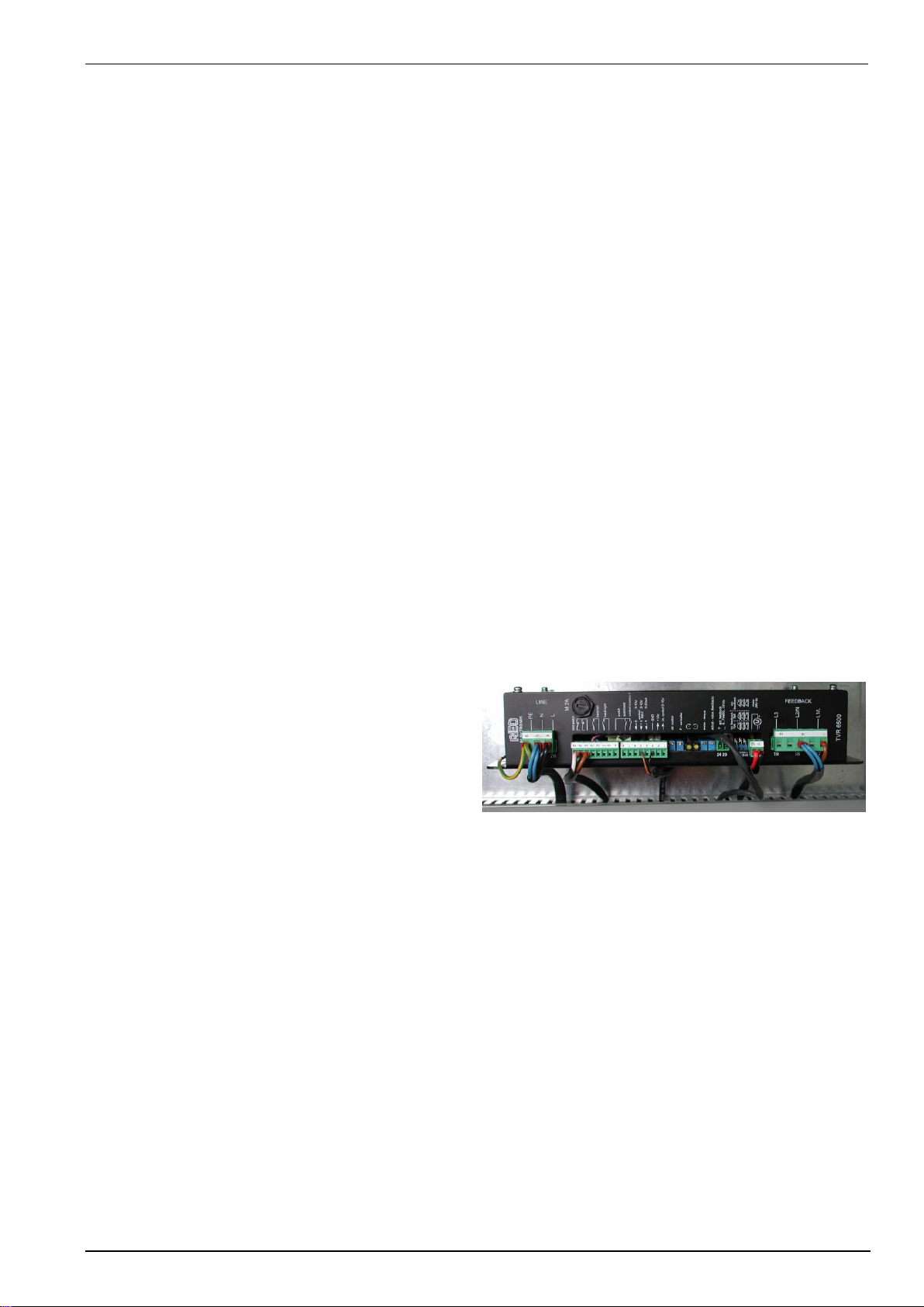
Figure 2.1: Rear side variac NX 1-260-16
1output PF1
2output PF2
3output neutral
4output protective earth
5fuse for F1 for PF1
6fuse for F2 for PF2
7control voltage 0-10 V dc
8power supply switch
9main fuse F3
10 main fuse F4
11 power supply input
1 Output PF1
Output voltage for channel PF1 at the generator side (e.g. UCS 500M). The voltage is 100% of the input voltage
for the variac (at port 11). This voltage is normally the rated voltage of the EUT.
2 Output PF2
Output voltage for channel PF2 at the generator side. The voltage is adjustable in the range of 0-260V in case of
a 230V input voltage and 0 - 130V in case of a 115V input voltage (at port 11). This output is normally used for
voltage variations and to generate the 40% and 70% test levels for voltage dips testing.
3 Output neutral
This is the common neutral output for both channels PF1 and PF2.
4 Output protective earth
This is the common protective earth output for both channels PF1 and PF2.
Fix connected power supply cable.
5 Fuse for PF1
The output PF1 is fused by 20AT.
6 Fuse for PF2
The output PF2 is fused by 16AT.
7 Control voltage 0-10V
To control the output voltage of the motor variac this input shall be connected to the 0 - 10V control output of the
generators. The voltage settings than can be selected via the frontpanel keyboard of the simulator.
8 Power supply switch
Main power switch ON/OFF.
9 Main fuse F3
Mains input fuse 20A Line..
10 Main fuse F4
Mains input fuse 20AT Neutral.
11 Input connector
CEE Input connector for 1-phase.

AMETEK CTS variac-NX 1 series
Operating manual V 1.05 6 / 23
3.
Putting into Operation
Prior to unpack completely the equipment check if the packing materials do show visible damages. In this case
do not remove the equipment from packing.
3.1.
Inspection
Check if the equipment shows visible transportation damages.
3.2.
Supply voltage
Prior to turning on the equipment check if the selected supply voltage corresponds with the actual power supply
mains in your laboratory. Damages which may arise from wrong supply voltage are not covered by warrantee.
3.3.
Main socket and plug
Main socket, power-on switch and fuses are located at the rear part of the equipment.
3.4.
Safety aspects
This description contains the necessary information for the correct application of the product described below. It
is intended for use by technically qualified personal only. Please read carefully the the Safety manual
Qualified personnel are persons who, because of their training, experience and position as well as their
knowledge of appropriate standards, regulations, health and safety requirements and working conditions, are
authorised to be responsible for the safety of the equipment, at all times, while carrying out their normal duties
and are therefore aware of, and can report, possible hazards (Definition of qualified employees according to IEC
364).
Safety instructions
The following instructions are provided for the personal safety of operators and also for the protection of the de-
scribed product and connected equipment.
Warning !
Hazardous Voltage. Missing attention can lead to death, cause serious injury or damage.
•Disconnect from power mains supply before installation or dismantling work, as well as for fuse
changes or post installation modifications.
•Observe the prescribed accident prevention and safety rules for the specific application.
•Before putting into operation check if the rated voltage for the unit conforms with the local supply
voltage.
•
•
Emergency stop devices must be provided for all applications. Operation of the emergency stop must
inhibit any further uncontrolled operation.
•The electric connections must be covered!
•Earth connection must be checked for safe function after assembly!
Use According to Designation
The units described herein are electrical equipment for the use in industrial plants. They are not determined for
private households.
Units with open electric connections are determined for installation only.
3.5.
Switch on condition
After switching ON the equipment is set into the following condition:
- Output voltage is returning to zero position if no BNC signal is available
- Remote voltage depends to the voltage at the control input 0-10V DC.
3.6.
Remote control voltage
The output voltage level is controlled by an external DC-voltage signal
(0-10V DC). The output voltage is directly proportional to the input signal. The input voltage signal is connected at
the BNC-plug available at the rear panel of the equipment.
DC voltage
Position
Output voltage AC
0V dc
minimum
0V
10V dc
maximum
Maximum output voltage approx. 254V for variac NX 1-260-x models

AMETEK CTS variac-NX 1 series
Operating manual V 1.05 7 / 23
3.7.
Variac-NX 1-260-xx configuration in the generator setup menu
The setup procedure is described in the generator setup menu and the setup procedure for set voltage.
The generator menu offers two separate voltage settings for low and high mains voltage, e.g for labs with equip-
ment for 115 V and 230 V.
Setup Menu: Set voltage low/high UCS 500 Firmware V 6.01ax (UCS 500N5) V9.04ax (N7x) or higher
This menu offers two separate voltage settings for user that needs to test equipment for 115 V and 230V mains
supply. Thanks to the two settings, the user can keep the Motorvariac in the 230V position
Using a VARIAC-NX 1-260-16 with voltage selector switch:
- Set the voltage selector to the 230V position for low and high mains voltage supply.
- Use the Firmware with low and high settings and use the VARIAC-NX 1-260-16 for any supply in the 230 V
position.
3.8.
Output plugs
The AC source has two different power supply outputs at the rear panel of the equipment.
PF1: 100% output = nominal AC input voltage
PF2: Variable output voltage depends to the variac position
The output is realised with the three safety laboratory leads (black, yellow-green, black).
The PF1 output is connected to the PF1 input of the generator and the PF2 output is connected to the PF2 input
of the generator, e.g. the compact NX5.

AMETEK CTS variac-NX 1 series
Operating manual V 1.05 8 / 23
4.
Variac
4.1.
General
The equipment consists of a single-phase variable transformer with motor drive.
A main switch is provided at the input; glass tube fuses are mounted in the output for protection of the unit.
The regulation is realised by using a pulse duty regulator (TVR 6500). The regulator is fed over the control trans-
former (BV 16-149 with tapping at 115V).
All connections of the AC-DC-Supply unit are led on connectors or sockets.
The mains power supply is effected through an approx. 2 m long flexible lead with a shock-proof plug. The out-
puts are wired on safety laboratory sockets.
The equipment is protected against short-circuit by fuses.
4.2.
Function description
After installation of the connections the single-phase variable toroidal transformer can be put into operation.
The supply voltage for the regulator is adapted to the mains voltage fed by using the change-over switch S2.
Before switching on the main switch S1 it must be assured that the supply voltage at the regulator corresponds to
the prescribed value of 32 V-36 V.
If the supply voltage for the regulator is too low or too high, either the function of the regulator is not
assured, or the regulator may be destroyed by over voltage.
The output voltage of 0...260V is adjusted with a set point of 0...10V, DC over a BNC-socket.
4.3.
Overload
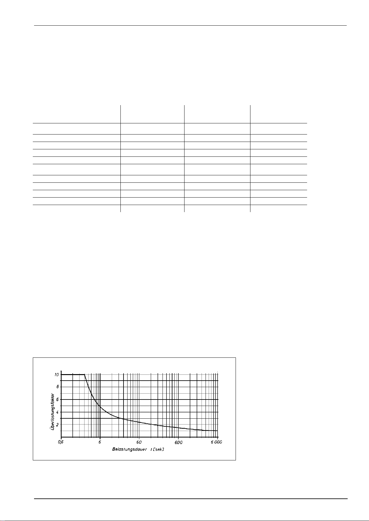
NOTE The variac NX is designed for high overload during short time as per the overload curve
below. For magnetic field test up to 1000 A/m the current transformer requires a primary
current uo to 39 A during 3 seconds. Therefore, it is required to use fuses with slow blow
characteristics, that are capable to support the required current.
Figure 4.1: Overload curve of Variac NX 1-xx series
AMETEK CTS variac-NX 1 series
Operating manual V 1.05 9 / 23
5.
Controller type TVR 6500
5.1.
General
Control Unit for Motorised Variable Transformers
Variable power supplies within the mains voltage and high power range, in the most of the cases, are realised
with variable transformers. In general, it is not sufficient to just adjust the voltage or resp. the power, but it is often
necessary to keep the adjusted value constant. For this purpose, the variable transformer is driven by a motor
which is controlled by a suitable electronic regulator. The unit described below, is such an electronic regulator for
controlling a DC motor with a permanently excited field.
The regulator essentially comprises the following main components:
A power supply, within a voltage range of 80 to 265 VAC, provides the internally required operating voltages and
the operating voltage for the servo motor.
The regulator circuit compares the selected set point voltage with the fed back actual voltage, and in case of de-
viation, produces an error signal, corresponding in amplitude and polarity, which is transmitted to the motor drive
circuit.
The actual value input is followed by a precision rectifier which generates the required signal voltage
for the regulation circuit from the connected actual value voltage (DC/AC).
The motor drive circuit, in case of deviation between set point and actual value, receives an error signal from the
regulator circuit. This signal is converted into a variable pulse-duty factor. The pulse-duty factor determines the
adjusting speed of the motor and the direction of rotation of the motor. The input signals of the end limit switches
are logaically connected to the direction of rotation signals and thus limit the adjustment range of the drive gear.
5.2.
Function description TVR 6500
Set point inputs:
The set point can be derived in various ways. Basically
the set point is a 0...10 V, DC voltage signal. It can
either use a 0...10 V control direct or a control potenti-
ometer fed from the internal 10 V reference voltage
source. An input for a 0...20 mA, DC control current is
likewise available.
By using the additional switching function (set point 1 and set point 2), two different set points can be operated
eg. hand adjusted potentiometer for set point 1 and an external control voltage from a supervisory control system
for set point 2. By switching the input, set points 1 and 2 can be changed from one to the other.
If the set point is to remain fixed (voltage stabilser system), then the internal trimmer can be used by inserting a
jumper link.
Feedback Input:
Depending upon the output rating of the complete system which is to be controlled, the feedback signal can de-
rived in various ways. The standard unit has three possible feedback ranges:
0...10 V, DC - corresponding to 0...100%
0...7 V (Effective) AC - 0...100%
0...500 V (Effective) using an internal voltage conversion transformers
Should there be other feedback voltage values, there is a bank of switches available for feedback selection. An
externally adjusted trimmer "ISTWERT" provides fine control of the system.

AMETEK CTS variac-NX 1 series
Operating manual V 1.05 10 / 23
5.3.
General functions of TVR 6500
Switching AUTO/HAND:
The normal operation of the unit is for the automatic regulation against a selected set point. However, by using
the switch AUTO/HAND the adjustment drive control method can be changed so that the drive system (e.g. trans-
former) can be controlled by push buttons for testing. The selected set point becomes ineffective. Also the
regulation operation is now no longer present.
Control Adjustment:
By the comparison of the set point voltage and the feedback voltage, the required correction signal is derived in
the PI-terms. The P-portion of the regulator is adjustable externally to alter the regulator characteristics of the
system (amplitude of the drive).
Control Signal for the Motor:
The correction signal of the regulator is connected to a saw tooth generator, which produces a pulse width modu-
lated correction signal. This means that a small variation will generate short pulses, where as a greater variation
will produce longer pulses. The correction signal is logically connected to the limit switches and also to a motor
bridge drive. The motor is connected to the output of the bridge drive.
Features:
Set point
0...10 V/0...20 mA
Switching for two set points
(closed = 2. set point)
Switching for testing (without regulation)
(closed = manual operation)
Internal 10 V - reference voltage
Internal set point setting option
Measured voltage input
0...10 V, DC
Measured voltage input
0...10 V SS AC / 0...7Veff AC
Internal voltage measurement transformers
(up to 500V)
Inputs for limit switches (inhibit)
(Inhibit)
Proportional speed control correction
Adjustable motor response
Adjustable regulation characteristic (P-term)
Dead time
ca. 200ms
Built into a
snap-on module for DIN rail mounting
Motor voltage
24 V, DC - 1 A max.
Supply voltage
80V-265 V AC

AMETEK CTS variac-NX 1 series
Operating manual V 1.05 11 / 23
5.4.
Wiring diagram TVR 6500
26 27 28
9 10 11 12 13 14 15 16
1 2 3 4 5 6 7 8
23 24
31 32
17 18 19
PE
L
N
Voltage supply regulator
80 - 265V AC
Limit switch clockwise rotation
Hand anticlockwise rotation
Change-over Soll1 / Soll2
Change-over Auto / Hand
Internal set-point 0...10VDC
+10Vref
Set-point 0...20mA
Set-point 1 0...10V
Set-point 2 0...10V
Ground/ GND
Set-point intern
P - term (Servo amplifier)
Display direction of rotation
Initial breakaway torque
Actual value
+
-Actual value feedback
0-7Veff or 0...10VDC
Change-over actual value
0...10V or mains voltage 1/3 phase
open 0...10V, closed mains feedback
Servo motor 24VDC
L3
L2 / N
L1 / L
Actual value feedback
1 / 3 Phase
Limit switch anticlockwise rotation
Hand clockwise rotation
26 27 28
9 10 11 12 13 14 15 16
1 2 3 4 5 6 7 8
23 24
31 32
17 18 19
PE
L
N
Voltage supply regulator
80 - 265V AC
Limit switch clockwise rotation
Hand anticlockwise rotation
Change-over set-point I/II
Change-over Auto / Hand
Internal set-point 0...10VDC
+10Vref
Set-point 1 0...20mA
Set-point 1 0...10V
Set-point 2 0...10V
Ground / GND
Set-point intern
P - Term (Servo amplifier)
Display direction of rotation
Initial breakaway torque
Actual value
+
-Actual value feedback
0-7Veff or 0...10VDC
Change-over actual value
0...10V oder mains voltage 1/3 phase
open 0...10V, closed mains feedback
Servo motor 24VDC
L3
L2 / N
L1 / L
Actual value feedback
1 / 3 Phase
Final adjustment
7K5 10K
Limit switch anticlockwise rotation
Hand clockwise rotation

AMETEK CTS variac-NX 1 series
Operating manual V 1.05 12 / 23
6.
Maintenance of Air cooled variable Transformers
To ensure a trouble free operation of the variable transformer, after running time of approximately 4000 hours, or
1 year after installation, and at the latest after further approximately 8000 oiperating hours (2 years), the following
maintenance procedure is recommended
1. The carbon rollers/brushes must be checkedfor free movement and spring tension. Contact pressures be-
tween the roller brush and contact track is most important
2. Sized worn or flat sided carbon rollers and brushes must be replaced immediately, otherwise the winding,
brush-holder or contact surface are likely to be damaged.
3. The contact surface should then be cleaned with a stiff brush, to remove adhered dirt. Alternatively the con-
contact surface can be cleaned with a contact cleaner lubricat, which must be completely removed following
cleaning.
4. Brush guides and contacts must be examined for abrasion. Badly worm parts should be replaced
5. Transformers with spindle drives should be greased on bearings and shafts. The bearing block should be
lubricated. Also the contact should be treated with a contact spray.
For more demanding duty, as per 0552 G Standard, the operating time should be reduced to approximately
1500 –2000 hours and the further routine maintenance is recommended at approximately 4000 operating
hours.

AMETEK CTS variac-NX 1 series
Operating manual V 1.05 13 / 23
7.
Application and setup
7.1.
Application for IEC 61000-4-11
The motorized transformer variac-NX 1-260-16 can be used with the equipment listed below:
- compaxt NX5 series
- PFS 500N series
- PFS 503N series for 1-phase application
- UCS 500N series
The motor variac can be used to simulate power supply failures as undervoltages, voltage interruptions and voltage
variations. The Basic Standard IEC 61000-4-11 and the Generic Standard EN 61000-6-1 / 2 are specifying these
phenomenas.
Voltage interruptions (DIPS)
Voltage interruptions will cause a reduction of the power supply voltage for a certain period of time. see figure. 10.1.
Three different test levels are required:
DIP 60% 10ms
DIP 30% 100ms
100%
70%
40%
t
Un
Reduction by:
- 100% = reduction to 0% of the nominal voltage
- 60% = reduction to 40% of the nominal voltage
- 30% = reduction to 70% of the nominal voltage
- 20% = reduction to 80% of the nominal voltage
Figure 7.1: Voltage dips
Voltage variation
Additionally, it is possible to drive certain functions of variation, which also are required in older versions of the
standard IEC 61000-4-11. These functions can easily be programmed within the simulators itself or within the related
windows software.
Figure 7. 2: Voltage variations

AMETEK CTS variac-NX 1 series
Operating manual V 1.05 14 / 23
7.1.1.
Test setup for dips and interruption
The transformer will be connected as in figure 7.3:
The motor variac must be connected to the
rear panel of the UCS 500. For connection
safety laboratory leads, shall be used.
The control a BNC cable shall be used.
Figure 17.3: Connection diagram variac NX
1-260-16 and compact NX generator.
7.1.2.
Test setup for dips and interruption
For detailed infos refer to the manual for magnetic field testing
Test setup for 1 A/m to 30 A/m
Figure 7.3
Test setup for 100 A/m to 1000 A/m
Figure 7.4
AMETEK CTS variac-NX 1 series
Operating manual V 1.05 15 / 23
8.
Technical data
8.1.
Technical data variac-NX 1-2xx-yy family
Input:
VoltageUin: nominal 230 V, max. 250V
Frequency : 50/60Hz
variac-NX 1-260-16
variac-NX 1-260-32
variac-NX 1-280-
16
Output:
Output voltage output PF1
230 V
230 V
230 V
Output voltage output PF2
0 –260 V approx..
0 –260 V approx..
0 –280 V
Current I max :
16 A
32 A
16 A
Power
0 - 4.1 kVA
0 - 8.2 kVA
0 - 4.48 kVA
Dimensions and weight:
Dimensions
19" 6 units
Special cabinet
19" 6 units
(HxWxD)
266x485x400 [mm]
680x600x410 [mm]
266x485x400 [mm]
Weight
app. 34.6 kg
app. 65 kg
app. 34.6 kg
Power supply
85 V –256 VAC
85 V –256 VAC
85 V –256 VAC
Environment Tmax
40°C
40°C
40°C
Control:
Main switch On/Off for the output voltages
Control voltage 0 –10 V DC for 0-260 V, 0-280 V
Time 0…100% < 2 s
Protection IP 20
8.2.
Environmental conditions
Temperature
10 °C to 35 °C
Hunidity
30 % to 70 %; non condensing
Atmospheric pressure
86 kPa (860 mbar) to 106 kPa (1 060 mbar)
=> All parameters that are not relevant for the standard can be changed by manufacturer <=
Overload
Figure 8.1.4 Load diagram variac NX transformer

AMETEK CTS variac-NX 1 series
Operating manual V 1.05 16 / 23
9.
Model design
9.1.
variac-NX 1-260-16 and variac NX 1-280-16
The equipment consists of a single toroid transformer with motor drive. The regulation is realized by using a duty
regulator (TVR 6500 model)
Figure 9.1: Front variac-NX 1-260-16.x
Fi Figure 9.2: Rearside variac-NX 1-260-16.x gure 12.3:
VARIAC-NX 1-260-16 internal wiring
Fuses
The equipment is protected against short-circuit by fuses.
Fuses: SIBA Type 189140.20
Size: 6.3 x 32mm
Figure 9.3
Fuse destination current character Voltage
F1 to PF1 20 A T time lag 440 V
F2 to PF2 20 A T time lag 440 V
F3 mains input line 20 A T time lag 440 V
F4 mains inputneutral 20 A T time lag 440 V
Internal Fuse
Fuses: SIBA Type 172530.1
Size: 5 x 30mm
F3 Power TVR 6500 1 A Med time lag 500 V
F4 Feedback transformer 1 A Med time lag 500 V
Figure 9.4
Fig 9.5
AMETEK CTS variac-NX 1 series
Operating manual V 1.05 17 / 23
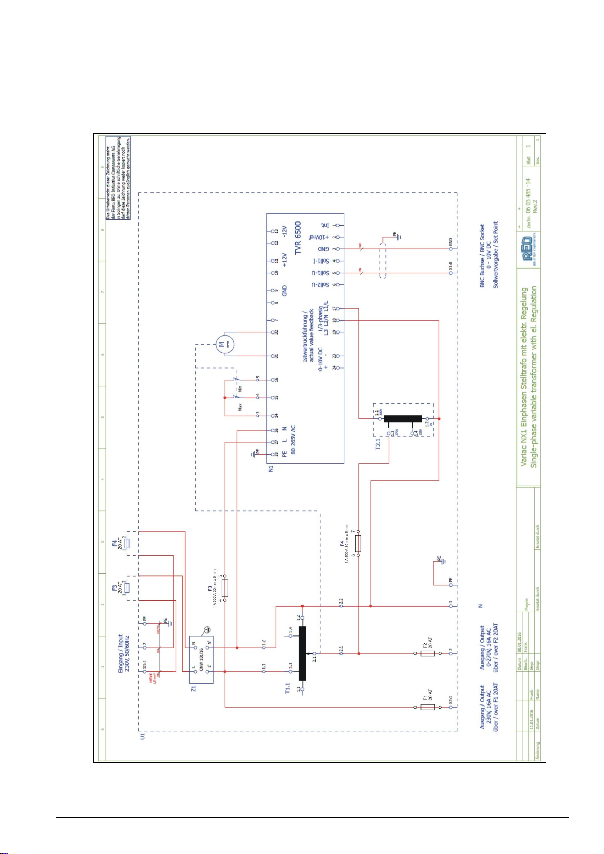
9.1.1.
Diagram variac NX 1-2x0-16
Motorvariac variac-NX 1-260-16
Motorvariac variac-NX 1-280-16

AMETEK CTS variac-NX 1 series
Operating manual V 1.05 18 / 23
9.2.
variac-NX 1-260-32
The equipment consists of a single toroid transformer with motor drive. The regulation is realized by using a duty
regulator (TVR 6500 model)
Switch S2
The switch S2 is used vor the match the voltage PF2 to the internal regulator. There are two position.
Position S2
Voltage range
115 :
0-130V
230 :
0-260V
Fuses
The equipment is protected against short-circuit by fuses.
F1.1 to PF1 35A
F1.2 to PF2 35A
F2.1 to feedback transformator 1A
F3.1 to regulator 3.15A
Fuses: Type:
NEOZED 35A ;400V AC
series : 5SE2
size : D02
1A; 3.15A 500V
size : 5 x 30mm
type time lag
Figure 9.5: Fuses variac NX 1-260-32
Figure 12.6: variac NX 1-260-32 frame
Figure 12.7: variac NX 1-260-32 internal wiring

AMETEK CTS variac-NX 1 series
Operating manual V 1.05 19 / 23
9.2.1.
Diagram variac NX 1-260-32

AMETEK CTS variac-NX 1 series
Operating manual V 1.05 20 / 23
10.
Appendix
10.1.
Declaration of conformity
The variac NX 1-260-xx models are exclusive manufactured for AMETEK CTS by REO. Please refer to the decla-
ration of conformity of the manufacturer:
This manual suits for next models
2
Table of contents
Other EMTEST Test Equipment manuals

EMTEST
EMTEST CNI 503 Series Technical Document

EMTEST
EMTEST PFM 200N200 User manual

EMTEST
EMTEST CWS 500A / 75 User manual

EMTEST
EMTEST PFM 200N100.1 User manual

EMTEST
EMTEST AN 200 Series Instruction Manual

EMTEST
EMTEST esd NX30 User manual

EMTEST
EMTEST dito User manual

EMTEST
EMTEST CNI 508 N2 User manual

EMTEST
EMTEST PFS 200N Series Instruction Manual

EMTEST
EMTEST VDS 200Q10 Series User manual


