Sealed Air Instapak 901 User manual

Instapak®901/970
Foam-in-Place Packaging System
User's Guide

Original instructions.

Instapak®901/970 System User's Guide Table of Contents
TABLE OF CONTENTS PAGE
IMPORTANT SAFETY PRECAUTIONS i
1.0 OVERVIEW 1 - 1
1.1 System Description 1 - 1
1.2 System Operation 1 - 1
1.3 Electrical Requirements 1 - 2
1.4 Space Requirements 1 - 2
2.0 OPERATION 2 - 1
2.1 The Console Control Panel 2 - 1
2.2 System Start-Up 2 - 3
2.3 Control Settings 2 - 3
2.3.1 Timer Modes 2 - 4
2.3.2 Setting Flow Rate 2 - 7
2.3.3 Setting Temperatures 2 - 7
2.4 Additional Features 2 - 9
2.4.1 The Shot Sequence Mode 2 - 9
2.4.2 Shot Storage Feature 2 - 12
2.4.3 Language Selection 2 - 16

Table of Contents
3.0 PACKAGING SUGGESTIONS 3 - 1
3.1 Foam-in-Place Packaging Method 3 - 1
3.2 Pre-Molding Packaging Method 3 - 5
4.0 MAINTENANCE 4 - 1
4.1 Preventive Maintenance Schedule 4 - 1
4.2 Holster Maintenance 4 - 2
4.3 Cartridge and Dispenser Maintenance 4 - 3
4.4 Chemical Container Replacement 4 - 14
5.0 TROUBLESHOOTING 5 - 1
5.1 Equipment/System Issues 5 - 1
5.1.1 Efficient Use of Foam 5 - 1
5.2 Troubleshooting Charts 5 - 2
6.0 APPENDIX 6 - 1
Accessories 6 - 1
Supplies 6 - 1
Parts 6 - 1
Customer Service Locations 6 - 2

Instapak®901/970 System User's Guide Safety
i
IMPORTANT SAFETY PRECAUTIONS
Read and thoroughly understand this guide.
Warning Symbols:
This "bolt of lightning" indicates uninsulated material within
your unit that may cause an electrical shock. do not remove
the product cover.
This "exclamation point" calls attention to features for which
you should read the enclosed literature closely to prevent
operating and maintenance problems.
Before operating your Instapak®system, read and understand
the "RECOMMENDATIONS FOR THE SAFE USE
AND HANDLING OF INSTAPAK®FOAM-IN-PLACE
CHEMICALS" bulletin, and the Material Safety Data Sheets
(MSDSs) provided for Instapak®products.
If additional copies of the "RECOMMENDATIONS FOR
THE SAFE USE AND HANDLING OF INSTAPAK®
FOAM-IN-PLACE CHEMICALS" bulletin or MSDSs are
needed, please contact your local Sealed Air®sales or account
representative.
WARNING: To avoid overexposure to MDI vapors, never
dispense Instapak®"A" chemical unless making Instapak®
packaging foam. If system is not in normal operating
condition, DO NOT USE.
This "goggles" symbol calls attention to the need to wear
protective eyewear with side shields while performing
operating, maintenance, and repair procedures.
Be sure to turn the console OFF before performing main-
tenance procedures on the Instapak®901/970 system.

Safety
ii
Do not remove the covers. The covers should be removed only
by authorized Sealed Air®service personnel. Opening the cov-
ers exposes dangerous electrical shock hazards.
before operating, make sure that:
• Theoperatorhasreceivedfulltrainingbyauthorized
Sealed Air®personnel.
• Thesystemispluggedintoaproperlyrated,groundedoutlet.
(Refer to Section 1.3 of this guide)
Failure to properly ground the system could create an electrical
shock hazard.
Inspect the Instapak®901/970 system at regular intervals to
ensure that:
a. Component hoses and cables are not cut, broken or damaged.
b. No components of the dispenser, console or pumps are loose.
c. All controls and indicators function properly.
If operation of the system differs from the descriptions in this
guide, turn the system off and disconnect the main power until
the unit can be inspected by a Sealed Air®representative.
We strongly recommend that customers use only Instapak®
chemicals with Instapak®systems. We can assume no responsi-
bility when other chemicals are used in Instapak®systems, and
we reserve the right to refuse to service any Instapak®systems
if non-Instapak®chemicals or parts have been used. Service
includes, without limitation, providing repairs and maintenance
services, supplies and parts.
Do not attempt to repair or modify the Instapak®901/970
system other than the procedures contained in the
troubleshooting section of this guide. All repairs must be
done by authorized Sealed Air®service personnel.

Instapak®901/970 System User's Guide Safety
iii
In accordance with the provisions of the EC Machinery Directive (2006/42/
EC), EC Low Voltage Directive (2006/95/EC) and EC Electromagnetic Directive
(2004/108/EC) the following applicable standards documents were used:
For all 901 and 970 systems:
EN 60204-1, EN 13849-1, EN 14121,
EN ISO 12100-1, EN ISO 12100-2,
EN ISO 13857, EN 349, EN 953-1,
EN 55011, EN 61000-4-2, EN 61000-4-3,
EN 61000-4-4, EN 61000-4-5, EN 61000-4-6,
EN 61000-4-11, EN 61000-6-2, EN 61000-6-4
SHOULD YOU ENCOUNTER A PROBLEM WITH YOUR
INSTAPAK®901/970 SYSTEM THAT YOU CANNOT FIX
WITH THE HELP OF THIS MANUAL, PLEASE CALL
SEALED AIR FOR TECHNICAL ASSISTANCE.

Safety
iv
NOTICE
© Copyright 2006 by Sealed Air Corporation (US). All rights reserved.
This document is copyrighted. The material contained herein is protected under
the US Copyright Act of 1976. This document, in whole or in part, may not
be copied, photocopied, reproduced, translated or reduced to any electronic
or machine-readable form without the prior written permission of Sealed Air
Corporation (US).
AIRBORNE NOISE EMISSION
For all 901 and 970 systems, the continuous A-weight sound pressure level does
not exceed 70 dB(A) during normal operations.

Instapak®901/970 System User's Guide Overview
1 - 1
1.0 OVERVIEW
The Instapak®901/970 foam packaging system dispenses a mixture of
Component "A" and Component "B". When mixed, the "A" and "B"
components react with each other to produce high quality polyurethane
packaging foam.
1.1 SYSTEM DESCRIPTION
The Instapak®901/970 system is made up of 4 major parts. Refer to
Figure 1-1, page 1-3.
1) Set of two electric pumps.
2) Electrically operated dispenser.
3) Computer operated console.
4) Heated component hoses.
1.2 SYSTEM OPERATION
The "A" and "B" components are pumped from the supply containers by
the "A" and "B" pumps into the heated hoses and through the dispenser.
The dispenser is supplied with a holster that keeps the tip clean and
ready for use. The hoses are suspended from a tool balancer that
supports their weight and allows them to be maneuvered easily.
Overview
1 - 2
1.3 ELECTRICAL REQUIREMENTS
NOTE: The Instapak 970 system requires 7 bar clean dry shop air at the
chemical container location.
1.4 SPACE REQUIREMENTS
The location selected for the Instapak®system should meet the following
criteria:
• Easilyaccessiblespaceforthe"A"and"B"componentcontainers.
The containers must be located within 1.5 m of the console, and
within 3 m of the dispenser.
• Asuitablewallspacetoaccommodatethecontrolconsole.Thepower
outlet for the console must be within 1,5 m of the console, and easily
accessible to the operator. The console should be fastened to the wall
approx. 1,5 m from the floor to the center of the console, to allow
easy access by the operator.
• Astructureatleast3,5mhigh,strongenoughtohangthetool
balancer and component hoses.
• AnInstapak®workstation is also available for ease of
installation. Ask your Sealed Air®account representative for details.
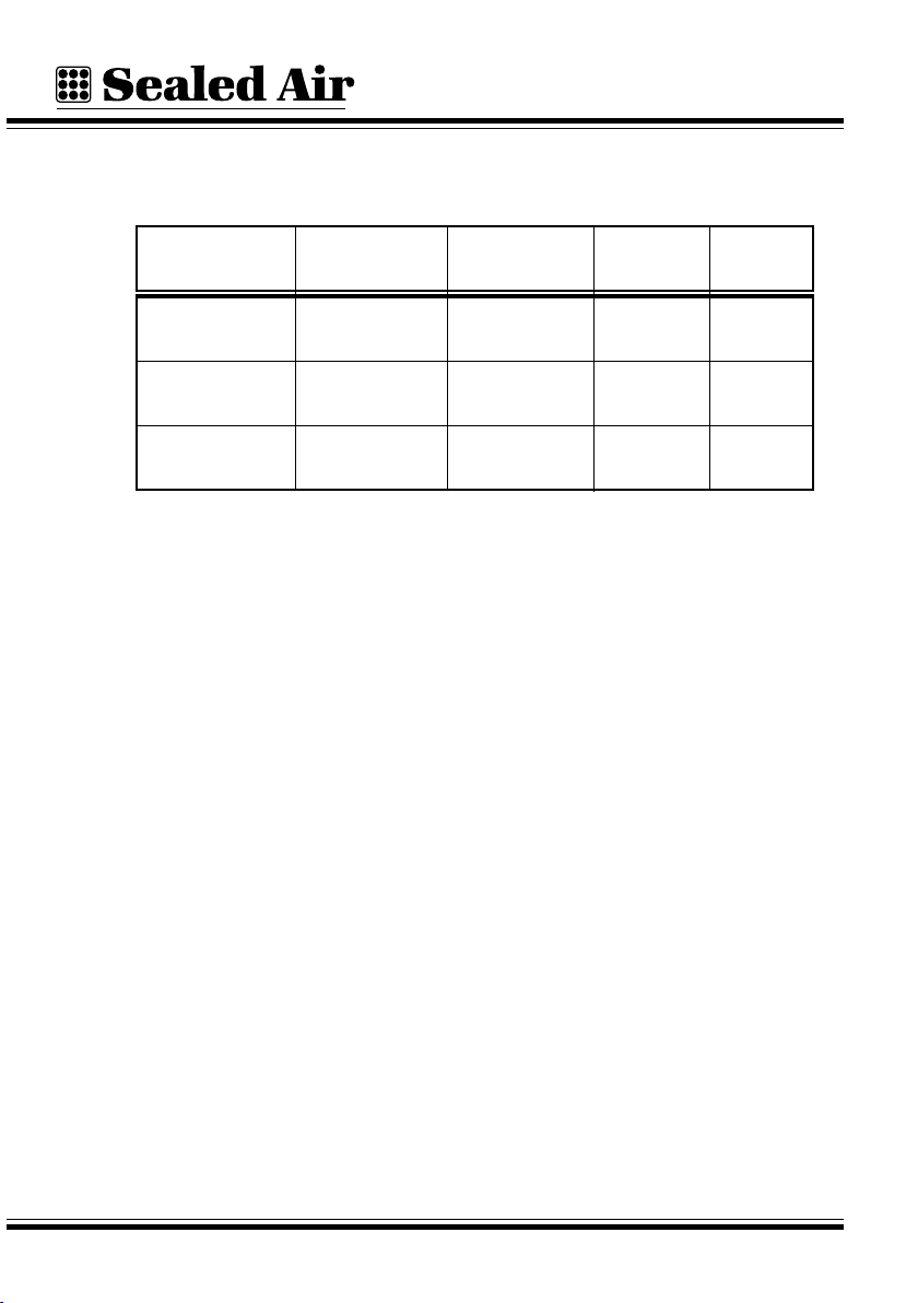
SYSTEM RECEPTACLE
TYPE A/C VOLTAGE PHASE CURRENT
Instapak®901/970
Instapak®901Y/970Y
Instapak®901D/970D
NEMA L6-30R
CEE type CT
516/6h
CEE type CT
432/9h
200 - 240 VAC,
50/60Hz
380 - 415 VAC,
50/60Hz
220 - 240 VAC,
50/60Hz
Single
Phase
3 N PE
3 PE
30 Amperes
16 Amperes
20 Amperes
Instapak®901/970 System User's Guide Overview
1 - 3
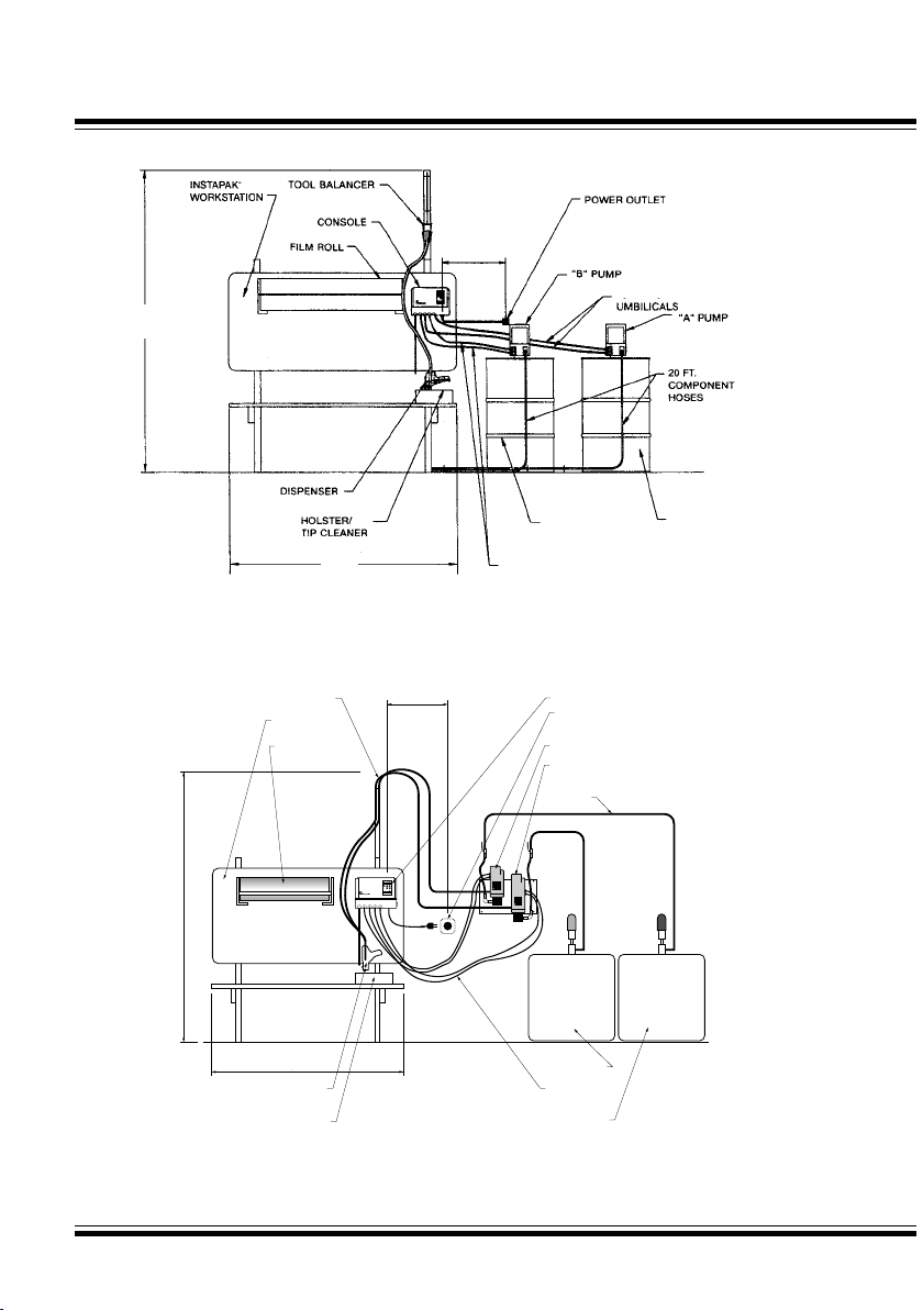
Fig 1-1 Typical Layout of the Instapak®901 System
Fig 1-2 Typical Layout of the Instapak®970 System
A
CHEMICAL
Instapak
®
900
Reset +
-
+
-
AB
AB
12
B
CHEMICAL
A
Instapak
B
Instapak
Instapak®
Workstation
Tool Balancer 5 Ft. Max.
13 Ft. Pump
Umbilicals
"A" Pump
Chemical
Lines
"B" Pump
Power
Outlet
Console
Film Roll
Dispenser
Holster/
Tip Cleaner
6 Ft.
8 Ft.
"A" Bulk Tank
"B" Bulk Tank
COMPONENT "B"
DRUM
COMPONENT "A"
DRUM
4 m PUMP
UMBILICALS
1,5 m
2,45 m
1,5 m MAX
4 m PUMP
1,5 m
1,5 m
2,45 m
4 m Pump

Overview
1 - 4
NOTES

Instapak®901/970 System User's Guide Operation
2 - 1
2.0 OPERATION
2.1 THE CONSOLE CONTROL PANEL
To operate the Instapak®901/970 system, push the main power switch
(1), on the right side of the console, to the "ON" position.
The Instapak®901/970 System Control Console
I
O
ON
OFF
Main Power Switch
Instapak
®
901
Reset
+
-
1
Operation
2 - 2
Instapak® 901
Reset
+
-
3
3
2
5
2
4
1
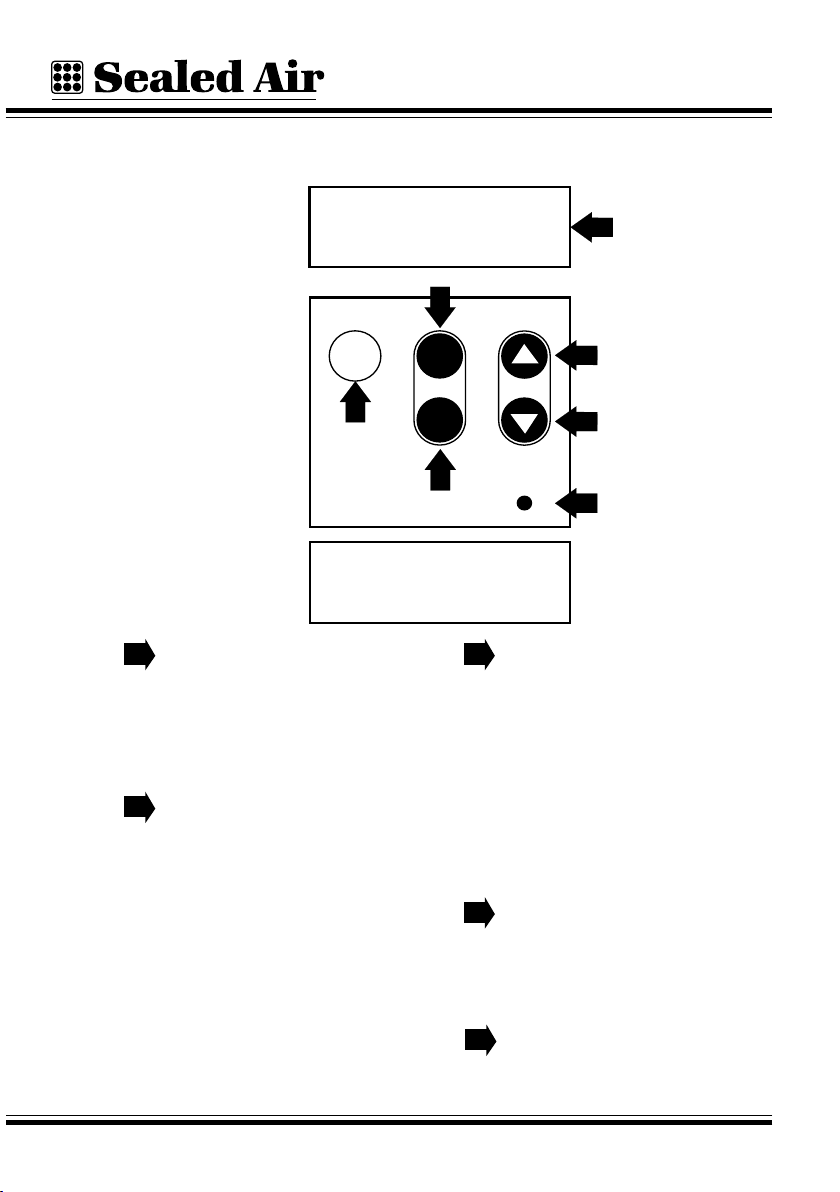
The controls are located on the front of the console. See the figure
below.
The Display.
This window displays messages
from the system and a number of
options you can change within the
system.
The Menu UP ▲ and Menu
DOWN ▼ keys.
These keys allow you to change the
window being displayed. Push the
Menu UP ▲ key to change to the
next window and push the Menu
DOWN ▼ key to change to the
previous window shown.
The Adjust PLUS + and
Adjust MINUS - keys.
These keys allow you to change
settings. Use the PLUS (+) or
the MINUS (-) key to increase or
decrease the value by one unit.
Hold down a key, and the value
will continue to change at a faster
rate.
The RESET key.
Push the RESET key to restart the
901/970 system after a shut-down
has occurred.
The LED.
This will light up when the system
is on.
1
2
3
4
5
SYSTEM STATUS WARM-UP
DISPENSER: OK
A DRUM: 3/4 FULL
B DRUM: FULL
Instapak®901/970 System User's Guide Operation
2 - 3
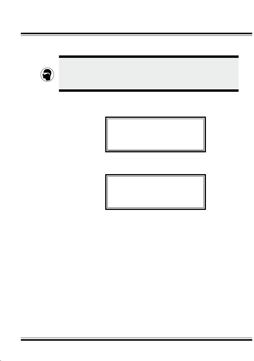
2.2 SYSTEM START-UP
When the system is first turned on, the displays will read all zeros, then
change to all ones. Then the display will read:
The display will show this message until the system has reached the
proper operating temperature and pressure. Then, the display will read:
NOTE: "A" and "B" drum level will not be shown on 970 systems.
You are now ready to dispense Instapak®foam.
• Removethedispenserfromtheholster.
• Squeezethetriggertodispensefoam.
• Releasethetriggertostopdispensingfoam.
• Placethedispenserbackintotheholster.
2.3 CONTROL SETTINGS
This section explains how to adjust basic settings: Timer, Flow Rate, and
Temperatures.
The settings are made by observing the display and then using the keys
on the control console to make selections or change numerical values.
The display shows a series of menus or "windows." Moving from one
window to another is accomplished by using the Menu UP ▲ and Menu
DOWN ▼ keys.
CAUTION
SAFETY GLASSES WITH SIDES MUST BE WORN WHILE
OPERATING INSTAPAK®EQUIPMENT.
SYSTEM STATUS WARM-UP
DISPENSER: OK
A DRUM: FULL
B DRUM: FULL
SYSTEM STATUS READY
DISPENSER: OK
A DRUM: FULL
B DRUM: FULL

Operation
2 - 4
2.3.1 TIMER MODES
You can choose between two modes, Manual Shot and Single Shot.
2.3.1.1 Manual Shot Mode
In Manual Shot mode the shot will last as long as you pull the trigger.
Use Manual Shot mode when you wish to manually control the foam
dispensing process. The system is configured to operate in the Manual
Shot mode after start-up. No adjustment to the system is necessary to
permit manual operation.
However, in Manual Shot mode you can, if you wish, determine the
length of any shot you have made. This information may be helpful for
programming timed shots into the system. To determine the length of a
manual shot, begin at the SYSTEM STATUS WINDOW:
NOTE: "A" and "B" drum level will not be shown on 970 systems.
•PresstheMenuUP ▲ key to show the TIMER MODE WINDOW:
•PresstheMenuUP▲ key again to show the LAST SHOT WINDOW:
SYSTEM STATUS READY
DISPENSER: OK
A DRUM: FULL
B DRUM: FULL
TIMER MODE
*MANUAL SHOT*
USE (+) OR (-) KEY
TO SELECT
LAST SHOT WAS
0.00 SECONDS

Instapak®901/970 System User's Guide Operation
2 - 5
•Squeeze the trigger on the dispenser. Foam will be dispensed and the
timer will count up from 0.00 seconds until you release the trigger. The
actual time of the shot will be shown in the LAST SHOT WINDOW,
for example:
The timer will automatically reset to 0.00 and time the next shot when
the trigger is squeezed.
2.3.1.2 Single Shot Mode
In Single Shot mode, when you squeeze the trigger, the shot will last as
long as the timed setting. Use this mode when you have a repetitive task
requiring the same amount of foam each time.
To set the length of a single timed shot, begin at the SYSTEM STATUS
WINDOW:
NOTE: "A" and "B" drum level will not be shown on 970 systems.
•PresstheMenuUP ▲ key to show the TIMER MODE WINDOW:
SYSTEM STATUS READY
DISPENSER: OK
A DRUM: FULL
B DRUM: FULL
TIMER MODE
*MANUAL SHOT*
USE (+) OR (-) KEY
TO SELECT
LAST SHOT WAS
2.33 SECONDS

Operation
2 - 6
•PressthePLUS(+)orMINUS(-)keytoselectSingleShotMode:
•PresstheMenuUP ▲ key and the display will read:
•PressthePLUS(+)orMINUS(-)keytosetthedesiredlength(in
seconds) of the single shot.
You can now dispense a timed shot. When you pull the trigger on the
dispenser, foam will be dispensed and the display will count down to
0.00 seconds. The shot will stop automatically at that time. The shot
will also automatically stop if you let go of the trigger.
At the end of the shot, the display will reset to the same number of
seconds. All subsequent shots will change automatically to the new set
point until the timer setting is changed again.
TIMER MODE
*SINGLE SHOT*
USE (+) OR (-) KEY
TO SELECT
TIMER SET FOR:
5.00 SECONDS
USE (+) OR (-) KEY
TO ADJUST

Instapak®901/970 System User's Guide Operation
2 - 7
2.3.2 SETTING FLOW RATE - THE FLOW RATE
WINDOW
The flow rate should be set to suit your particular packaging applica-
tions. A small box will use a slower flow rate; a large box will use a
faster rate.
•FromtheSYSTEMSTATUSWINDOW,presstheMenuUP ▲ key
THREE times and the display will read:
•PressthePLUS(+)orMINUS(-)keytochangetherateatwhichfoam
is dispensed. The higher the number, the faster foam is dispensed
(kilogram per minute).
2.3.3 SETTING TEMPERATURES - THE TEMPERATURE
WINDOWS
The temperature windows are used to control the temperatures of the
foam components in the hoses.
2.3.3.1 The "A" Temperature Window
•FromtheFLOWRATEWINDOW,presstheMenuUP ▲ key to move
to the "A" TEMPERATURE WINDOW.
•PressthePLUS(+)orMINUS(-)keytoadjustthe"A"component
temperature value.
FLOW RATE:
3.0 kg/m
USE (+) OR (-) KEY
TO ADJUST
A TEMPERATURE 60°C
USE (+) OR (-) KEY
TO ADJUST

Operation
2 - 8
2.3.3.2 The "B" Temperature Window
•Fromthe"A"TEMPERATUREWINDOW,presstheMenuUP ▲ key
to move to the "B" TEMPERATURE WINDOW.
•PressthePLUS(+)orMINUS(-)keytoadjustthe"B"component
temperature value.
B TEMPERATURE 60°C
USE (+) OR (-) KEY
TO ADJUST
This manual suits for next models
5
Table of contents
Other Sealed Air Packaging Equipment manuals


Popular Packaging Equipment manuals by other brands


Minipack-Torre
Minipack-Torre Pratika 56 CS Series Installation, operation and maintenance

Dispens-a-Matic
Dispens-a-Matic Bottle-Matic II Information and instructions

U-Line
U-Line H-7241 user manual

Greenbridge
Greenbridge PC1500 Operation manual & spare parts list

Proceq
Proceq ZAA 2600.HA instruction manual

Signode
Signode HSM 3000 operating instructions