Titan HPE-L User manual

Instruction manual
HPE - L
224 000200
.
Important!
Do not dispose of this manual. It is the
customer’s responsibility to ensure that all
operators and servicemen read and
understand this manual.
Combined strapping
tool for steel strap

HPE
H 224 EU 21/06
2.
General
These operating instructions are meant to facilitate acquaintance with the unit and its
intended use. They include important information on how the unit can be applied safely, as
intended and economically. Meeting instructions helps avoid risks, reduce repairs and
downtimes as well as increase the reliability and life of the unit.
The operating instructions must be available at the location where the unit is used. They
must be read and applied by all persons working with the unit. Such works especially include
operation, troubleshooting and maintenance.
Apart from the operating instructions and regulations for the prevention of accidents
applicable in the operator’s country and at the place of erection; further, the acknowledged
technical rules for safety-related and competent work have to be observed.
Explanatory notes on the warning and instruction symbols:
Caution!
Is used in case of risks to life and health.
Attention!
Is used in case of risks which may cause damage to objects.
Notice!
Is used for general information and notes, whose disregard
may lead to faults in the course of operations.
Copyright © TITAN Umreifungstechnik GmbH & Co.KG 2011 All rights reserved.
The contents of this document must not be duplicated, handed to third parties, published or saved in any form,
neither fully nor partly, without prior written permission by TITAN Umreifungstechnik GmbH & Co.KG.
is a registered trademark of TITAN Umreifungstechnik GmbH & Co.KG.

HPE
H 224 EU 21/06
2.1.
Intended use
Proper use of this semi-pneumatic tool includes bundling, collecting and
securing by means of strapping using steel straps. Packed goods such as
section steel, packages of stone, paper, timber, etc. are suitableapplication
examples.
Unintended use!
Strapping material must not be used for the hoisting of loads, this
strapping tool may only be used as intended and specified above.
2.2.
Tool description
The TITAN HPE combines modern TITAN No-Seal-Joint technology with the
advantages of power-saving pneumatics.
The HPE is based on thetried and tested HKE manual strapping tool with the
specially patented locking mechanism developed by TITAN. It reduces theforce
required and, compared to conventional tools, prolongs the service life of those
parts which are subjected to mechanical stress.
It has a suspension facility (snap hook) which makes weightlessstrapping
possible.
The TITAN HPE strapping tool satisfies German and European safety
requirements and complies with the provisions of the following EUGuidelines:
See declaration of conformity of the machinery
Standards applied and technical specifications:
See declaration of conformity of the machinery
2.3.
Instructions on environmental Protection Notice
No hazardous physical or chemical substances are used in
the manufacture of the devices. Comply with the applicable
regulations for disposal.

HPE
H 224 EU 22/10
3.
Technical data
Operating pressure: max. 6 bar flow pressure
Tensioningstrength: max.7000 N
Feed speed: 150 mm/sec
Air consumption: 0.36 m³/ min
Strap qualities: Automaten-, Megaflex- and Megaband
with blue, lacquered and zinc-dust coated
surfaces
Strap thickness: 0.5 to 0,8 mm for Automaten- and
Megaflex Band;
0.5 to 0.63 mm for Mega-Band
Strap widths: 13, 16 and 19 mm
Noise level: 78 dB (A)
Vibrations: < 2,5 m/s2
Dimensions: L = 360 mm
W = 160 mm
H = 160 mm
Weight: 5.5 kg

HPE
H 224 EU 21/06
4.
Safety regulations
Intended Use
Proper use of this pneumatic tool includes bundling, collecting and securing by mean of
strapping using still straps. Packed goods such as section steel, packages of stone,
paper, timber, etc. are suitable application examples.
The device was designed and built for safe operation during strapping.
The device is intended for strapping with steel packaging straps.
Possible misuse
The use of plastic straps is not allowed with this device.
Warranty and liability
TITAN Umreifungstechnik GmbH & Co. KG guarantees all strapping tools sold by the
company for a period of 6 months. The warranty covers all defects that can be demonstrated
to result from faulty craftsmanship or defective materials.
Wear parts are excluded from the warranty.
Warranty and liability claims shall be excluded if they are due to one or more of the following
causes:
Misuse of the tool.
Incorrect assembly, commissioning, operation and maintenance ofthe tool.
Operation of the tool with improper safety and protectivedevices.
Failure to comply with the information in theoperating manual.
Unauthorized structural modifications to the tool.
Insufficient monitoring of tool parts that are subjectto wear.
Improper repairs.
The manufacturer reserves the right to make changes to the scope of delivery at any time for
the purpose of improving the product.

HPE
H 224 EU 21/06
Failure to comply with the following safety instructions, in addition to errors in
handling the device, can result in serious injuries.
Be informed!
Read the operating manual carefully before using the device.
Protect yourself!
Always wear eye, face and hand protection (cut-resistant gloves)
when working.
Attention! Strap flies outward!
When cutting the strap, hold the top part firmly and stand to the
side.
Attention!
The lower part of the strap will fly outward.
Attention! Strap can break!
The strap can break during tightening! Do not stand in the path of
the strap. Make sure that no one else is in the working area.
Caution! Danger of crushing!
Do not insert fingers into the pulley area.
Caution! Strap only objects to be packed!
Make sure that no hands or other body parts are between the strap
and the goods to be packaged.
Use only original TITAN replacement parts!
The use of parts other than original TITAN replacement parts will
void the warranty and all liability.
Use only lifting gear that complies with the safety regulations!

HPE
H 224 EU 21/06
Do not exceed air pressure!
Never exceed the max. permissible air pressure of 6.0 bar.
Do not use gas or compressed air cylinders!
Do not connect the tool to a gas or compressed air cylinder.
The use of straps other than those recommended can result in
broken straps during the tightening process and insufficient
strapping.
Use only corresponding quality products from TITAN!
This device may be operated only by personnel who have been
trained accordingly. Please consult your TITAN packing
consultant if you have any questions about this.
Workplace
Always maintain an orderly workplace. A disorderly workplace can
cause accidents. When operating the crimper, make sure that you
are in a well-braced position in order to maintain optimum balance
and prevent the risk of falling.
Never operate the tool in an awkward working position!
Maintenance
In order to operate safely, the tool must be properly maintained.
Check the condition of your tool regularly for defects or worn parts.
Never use a tool that has defects or worn parts. Modifications to
the tool are strictly prohibited. Failure to comply with this
regulation can result in serious injury.
max. 6,0 bar

HPE
H 224 EU 21/06
5.
Putting into service
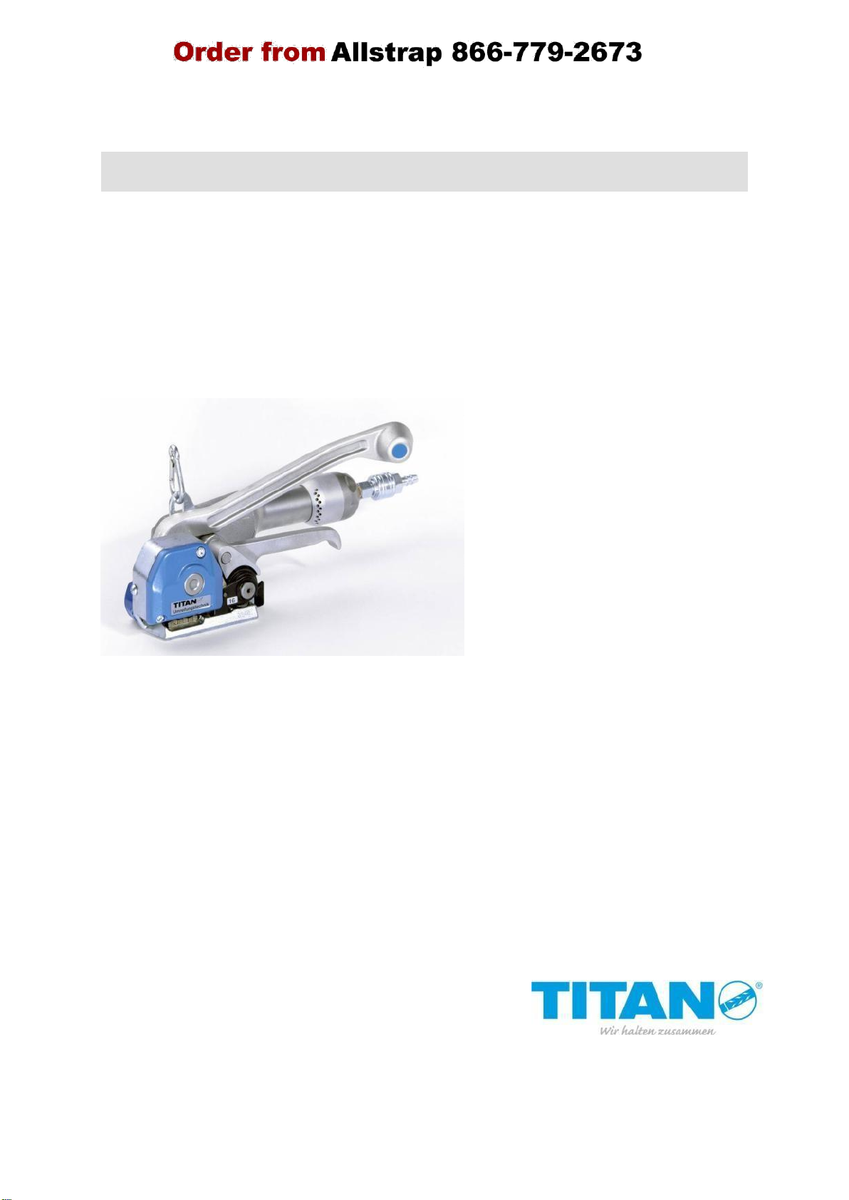
Connect the HPE strapping tool to the compressed air supply by means of the quick-action
coupling mechanism which is supplied. Maximum air pressure (see technical data).
Important: This tool may only be operated together with a compressed air maintenance unit
consisting of a pressure reducer, water separator and lubricator. It cleans the compressed
air, removes condensation and constantly supplies the motor with the required quantity of oil.
The lubricator is adjusted at the top by means of a screwdriver in such a way that a drop of
oil falls into the sight glass for each strapping. Rotation in a clockwise direction should result
in less oil, and in the opposite direction more. Maximum hose length between the
maintenance unit and the strapping tool: 5 m.
In no case it is allowed to run the tool without oil being in
the lubricator of the maintenance unit, as this would
immediately destroy the compressed air motor. No warranty
in that case.
The compressed air motor may be driven during the entire operation with filtered and
lubricated compressed air. In terms of quantity approximately 3 - 5 drops are required per
1 m3air; this corresponds to 0.12 - 0.2 g/m3. Unalloyed mineral oil should be primarilyused
as a lubricating oil. It should have a low viscosity and befree of resin and acids. A viscosity
of 2 - 4° E at 50° (12-30cSt) has been proven to be suitable (see viscosity table for other
temperature ranges). Permissible motor temperatures are from -30 to +100° C.
However, for ambient temperatures of under +5° C there is a risk of icing. In this case it is
recommended that dry air or corresponding lubricants which are resistant to icing be used
(e.g. "Killfrost Anti-Eis").
Caution! Wear respiratory equipment when antifreeze agents are used.
The following oils may
Esso
D 32
-10° to
+30°C
be used:
D 100
+25°
+55°
CL 320
+45°
+75°
DEA
Aries 32
Aries 100
-25° to
0°
+20°C
+50°
Shell
Tonna R 32
Tonna R 100
-10° to
+25°
+30°C
+55°
Mobil
Almo 525
-20° to
0° above
+20°C
Almo 527
+30°
Almo 528
+15°
The tool may be put into operation after connection to the compressed air supply and the
maintenance unit is adjusted.

HPE
H 224 EU 21/06
6.
Operating instructions
6.1. Design
6.2. Operating the unit
1.
Place TITAN steel strap around the
packing unit fromabove.
2.
Pull strap end through until it islocated
in the middle of the packing unit below
the upper strap and projects by a hand span.
b
d c
f
a
e
a = turning valve
b = cutting lever
c = lifting lever
d = feed wheel
e = gripper plate
f = compressed
air motor

HPE
H 224 EU 21/06
3.
Hold both of the precisely overlapping straps
firmly using your left hand. Using your
right hand takes hold of the lifting lever (c)
and cutting lever (b) and press together.
Push both straps laterally along the housing
wall into the tool as far as possible. A bit of the
lower strap has to project out of the front of the
tool. Release the levers (c) and (b).
4.
Using your right hand turn the ring ofthe
turning valve (a) to the left, to the limit.
The motor starts to run and tensions the strap.
After reaching the desired strap tension release
the ring. The turning valve closes automatically,
the motor is stopped. (The strap tension is
maintained by a free-wheeling mechanism.)
5.
The right hand takes hold of the compressed
air motor (f), the left hand grasps the cutting
lever (b) and pushes it rapidly forward up to the
stop at the housing. Thus, the TITAN "no-seal-
joint" is formed. At the same time the steelstrap
is cut off directly behind the joint.

HPE
H 224 EU 07/10
6.
Bring cutting lever (b) back into its initial
position and take hold of the cut off strap end
with your left hand. Lift the compressed air motor
(f) up to the limit and swing the tool to the
right out of the strapping.
The following picture shows a correctly carved seal.
Check the seals regular:
for even carved cuttings,
for neat cutting edges,
for that the lower run of strap is soaked inthe cuttings,
for correct adjustment of the cutter,
for a sufficient overlap of the lower run ofstrap and
for that the seal is placed in the centre of thestrap.

HPE
H 224 EU 21/06
h
g
7.
Adjustments
7.1. Cutter adjustment
The cutter has to be adjusted for the respective thickness in the case of varying
strap thickness.
Loosen locking screw (g). Turn stop screw
(set screw with flat point) (h) by means of
a Socket spanner in a clockwise direction
= less cutting depth; counter-clockwise =
greater cutting depth. Fasten locking
screw (g) after adjustment has been
completed.
After adjusting there should not be any, or very few, signs of cutting
on the lower strap.
7.2. Distance between the feed wheel and the gripperplate
The distance between the feed wheel (d)
and the gripper plate (e) is adjusted to 0.2
mm. The adjusting screw (i) is located
behind the plastic cover of the housing.
Unscrew the lock nut (k) using the 10 mm
open-jawed spanner and adjust a 0.2 mm
gap at the adjusting screw (i). Fasten lock
nut after adjustment has been completed
and fix plastic cover.
The feed wheel and the gripper plate may not come into contact
with each other, otherwise both parts will be subject to premature
wear.
k
i

HPE
H 224 EU 21/06
7.1. Adjusting strap width
The strap guide (n) located next to the feed wheel is replaced when the strap width is
modified. In order to do so the safety ring has to be removed by means of a
screwdriver and the lifting lever (c) and the cutting lever (b) pressed together. The
strap guide may now be pulled off toward the front and be replaced with the strapguide
for other strap widths. Replace safety ring afterwards.
Strap width 13 mm, order no. 2240001-500
Strap width 16 mm, order no. 2240001-501
Strap width 19 mm, order no. 2240001-502
Since the strap is guided at three points in the tool the rear strap guide (l) and the
adjusting screw (m) also have to be set in such a way that the punching is placed at
the centre of the strap.
In order to do this, loosen the two fastening screws for the rear strap guide and the
lock nut of the adjusting screw. The lock nut is located behind the plastic cover of the
housing. Tighten lock nut and fastening screws after adjustment has been completed.
Adjustment can be made easier by using a setting gauge or two strips of the strap
inserted into the HPE.
m
n
l

8.
Maintenance
8.1.
Cleaning and maintenance of theunit
Soil and debris hamper the proper functioning of the tool. For this reason, the following
areas should be cleaned once a week (blow off using compressed air if possible):
insertion slot,
cavities between the upper and lower knives,
tensioning wheel,
gripper plate
Lubricate with fine conventional spray oil afterwards.
Tool inspection!
Perform a daily visual inspection of the outside of the unit. The early detection of
damaged parts extends the life of the unit. Replace all damaged parts immediately
with Original TITAN spare parts.
HPE
H 224 EU 07/10
Do not use any solvent containing cleaning agents for
reasons of health.

`
9.
EC declaration of conformity of the machinery
This manual suits for next models
1
Table of contents
Other Titan Packaging Equipment manuals