SeaLevel SeaI/O Series User manual

Sealevel Systems, Inc.
Sealevel.com
Phone 864.843.4343

©Sealevel Systems, Inc.
SL9049 - 06/2011
SeaI/O Manual
2
SEAI/O USER MANUAL .................................................................................................................................1
PART#SEAI/O .............................................................................................................................................1
CONTENTS ...................................................................................................................................................2
BEFORE YOU GET STARTED.........................................................................................................................4
WHAT‟S INCLUDED ........................................................................................................................................4
ADVISORY CONVENTIONS ...............................................................................................................................5
INTRODUCTION ...........................................................................................................................................6
INDUSTRY SEGMENTS .....................................................................................................................................6
FEATURES.....................................................................................................................................................7
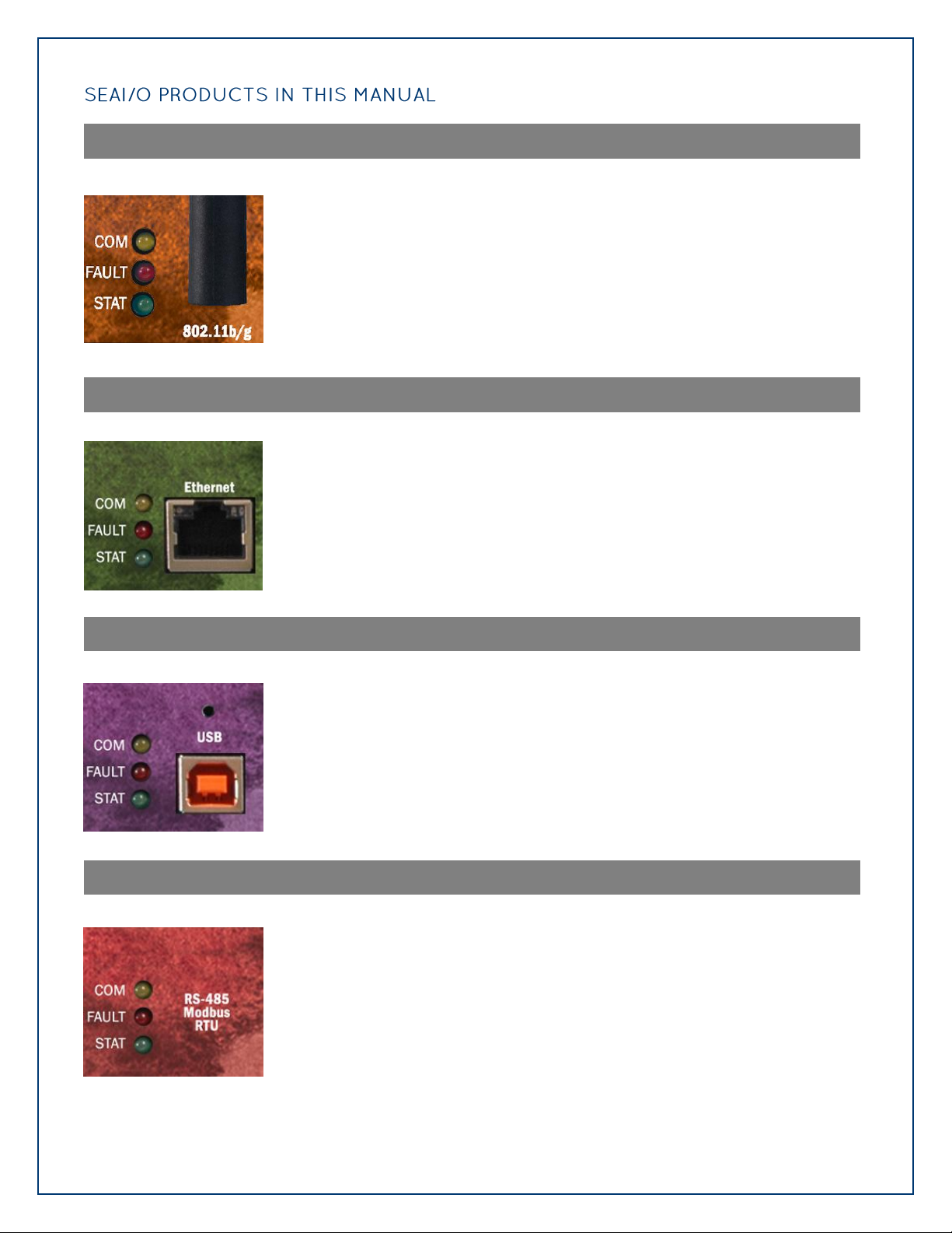
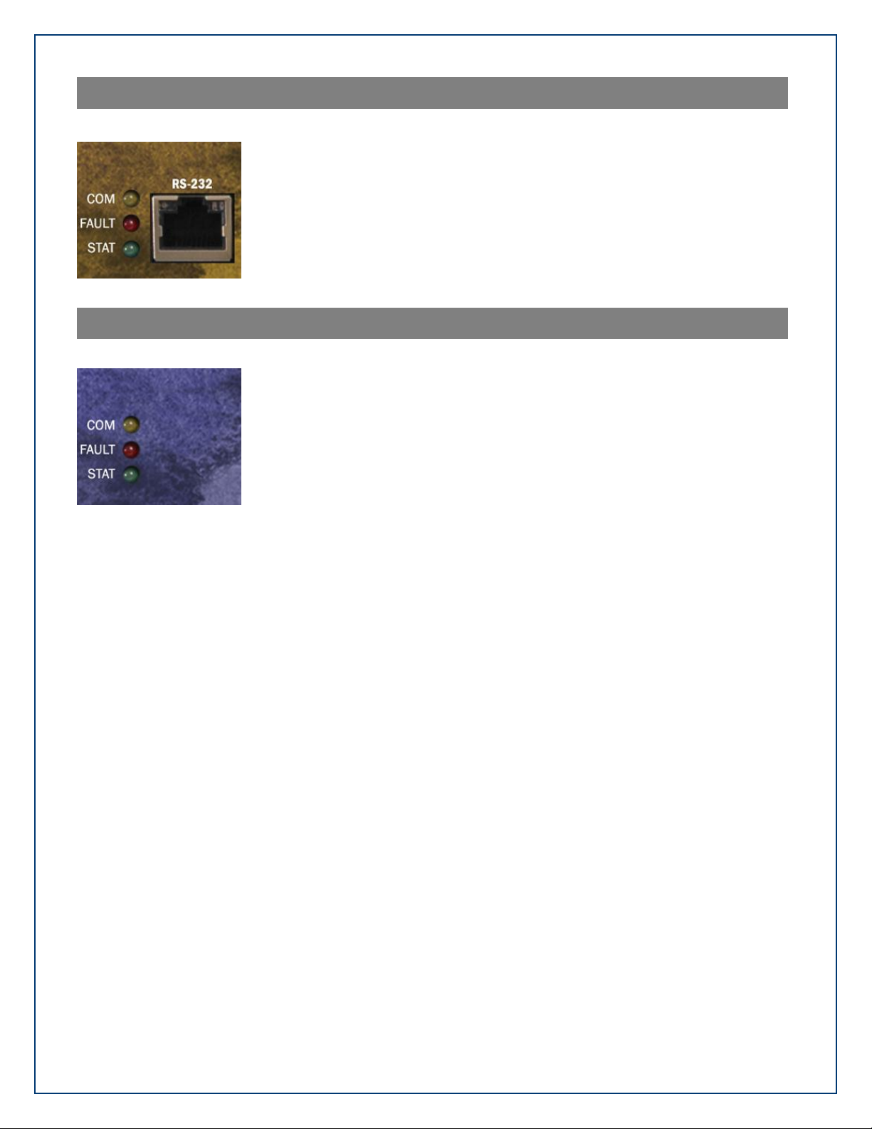
SEAI/O PRODUCTS IN THIS MANUAL ...............................................................................................................8
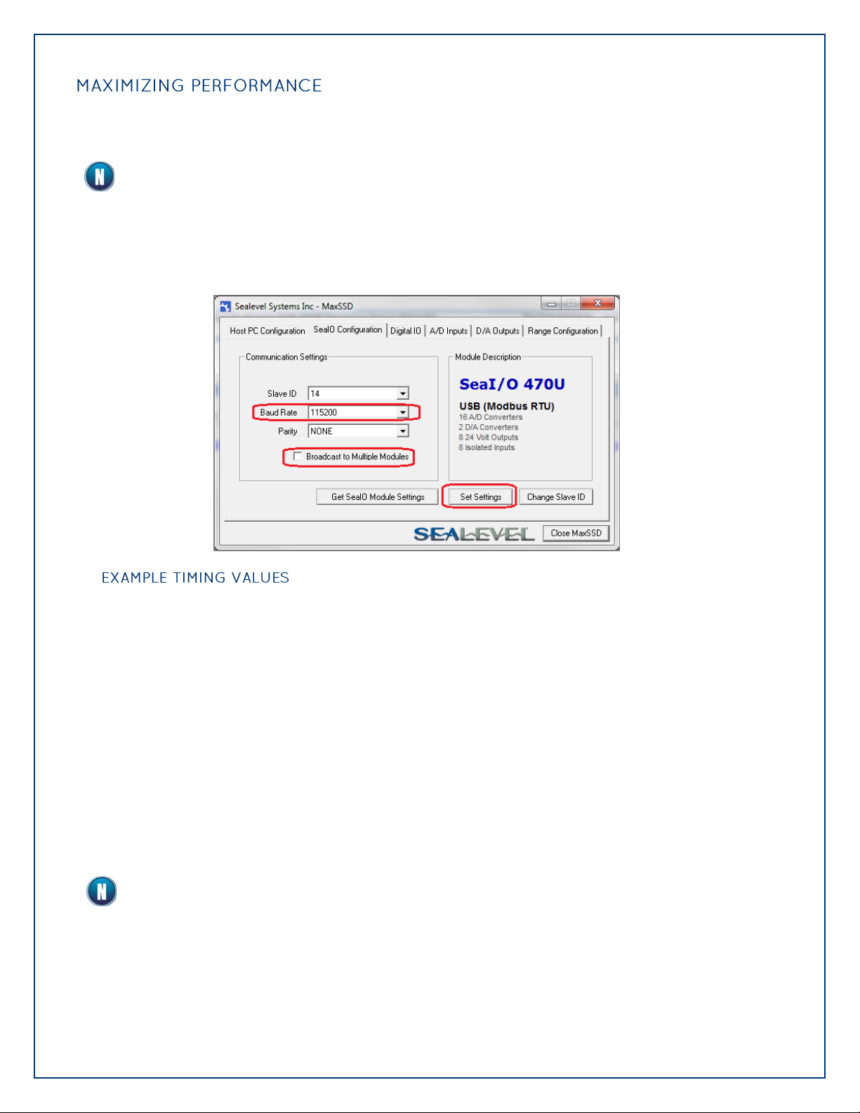
MAXIMIZING PERFORMANCE......................................................................................................................... 10
SEAI/O HARDWARE DESCRIPTION ........................................................................................................... 11
SEAI/O BASE AND EXPANSION MODULES....................................................................................................... 11
SEAI/O MODULE COMMON FEATURES .......................................................................................................... 12
SEAI/O CONFIGURATIONS &SPECIFICATIONS................................................................................................. 13
POWER OPTIONS ....................................................................................................................................... 35
BASE MODULE POWER CONNECTION ............................................................................................................. 35
SEAI/O EXPANSION POWER CONNECTION...................................................................................................... 35
SEAI/O MAX POWER REQUIREMENTS............................................................................................................. 35
TTLPOWER REQUIREMENTS......................................................................................................................... 36
SAMPLE POWER CALCULATION ..................................................................................................................... 36
SEAMAX APPLICATION SUITE ................................................................................................................... 37
SEAMAX OVERVIEW ................................................................................................................................... 37
COMMUNICATING VIA MODBUS.................................................................................................................... 37
SEAMAX SOFTWARE INSTALLATION .............................................................................................................. 38
DRIVER INSTALLATION FROM THE SEALEVEL DISK USING „AUTORUN‟................................................................. 38
INSTRUCTIONS FOR DOWNLOADED SOFTWARE INSTALLATION ........................................................................... 40
UPGRADING TO THE CURRENT SEAIO DRIVER (SEAMAX).................................................................................. 40
MAXSSD CONFIGURATION &DIAGNOSTICS UTILITY ....................................................................................... 42
TROUBLESHOOTING SEAMAX ...................................................................................................................... 50
TROUBLESHOOTING ETHERNET &WIRELESS SEAI/O MODULES.......................................................................... 51
HARDWARE CONFIGURATION .................................................................................................................. 52
SETTING DEVICE ADDRESS (SLAVE ID)........................................................................................................... 52
SETTING TERMINATION &PULL-UP/PULL-DOWN RESISTORS............................................................................. 53
CONFIGURING THE “BASE”SEAI/O MODULE................................................................................................... 54
CONFIGURING N-SERIES EXPANSION MODULES ............................................................................................... 55
CONFIGURING A WIRELESS (W-SERIES)MODULE .............................................................................................. 56

©Sealevel Systems, Inc.
SL9049 - 06/2011
SeaI/O Manual
3
CONFIGURING A WIRELESS MODULE .............................................................................................................. 57
CONFIGURING A WIRELESS MODULE .............................................................................................................. 58
WIRELESS MODULE INFORMATION................................................................................................................. 72
CONFIGURING AN ETHERNET (E-SERIES)MODULE............................................................................................ 74
ADVANCED FEATURES ................................................................................................................................. 77
SEAI/O-463 RIBBON CABLE INSTALLATION ................................................................................................... 81
SEAI/O-470 JUMPER AND DIPSWITCH SETTINGS............................................................................................. 84
SEAI/O-570 DIPSWITCH SETTINGS .............................................................................................................. 87
WIRING OPTIONS ...................................................................................................................................... 89
SEAI/O PASS-THROUGH CONNECTOR ........................................................................................................... 89
I/O WIRING –SEAI/O-462 AND 463 MODULES............................................................................................ 91
I/O WIRING –SEAI/O-470 MODULES .......................................................................................................... 95
I/O WIRING –SEAI/O-520 MODULES .......................................................................................................... 98
I/O WIRING –SEAI/O-530 AND 540 MODULES............................................................................................ 99
I/O WIRING –SEAI/O- 570 MODULES ....................................................................................................... 100
CONNECTOR PIN OUTS ............................................................................................................................. 103
MOUNTING OPTIONS.............................................................................................................................. 104
SEALATCH™ USB ..................................................................................................................................... 105
SEALATCH LOCKING USB CABLES............................................................................................................. 106
ACCESSORIES .......................................................................................................................................... 107
POWER SUPPLIES....................................................................................................................................... 107
MOUNTING OPTIONS ................................................................................................................................ 109
CABLING OPTIONS.................................................................................................................................... 110
APPENDIX A –HANDLING INSTRUCTIONS............................................................................................. 113
ESD WARNINGS ....................................................................................................................................... 113
APPENDIX B –HOW TO GET ASSISTANCE.............................................................................................. 114
TECHNICAL SUPPORT ................................................................................................................................ 114
WARRANTY.............................................................................................................................................. 115
WARRANTY POLICY................................................................................................................................... 115
NON-WARRANTY REPAIR/RETEST ............................................................................................................... 115
HOW TO OBTAIN AN RMA (RETURN MERCHANDISE AUTHORIZATION).............................................................. 115
TRADEMARKS .......................................................................................................................................... 115

©Sealevel Systems, Inc.
SL9049 - 06/2011
SeaI/O Manual
4
All SeaI/O modules are shipped with the following items. If any of these items is missing or
damaged please contact Sealevel for a replacement.
SeaI/O Data Acquisition Module
Sealevel SeaMAX Software CD
Do not connect the I/O module to the host until the software is installed.
All items can be purchased from our website (www.sealevel.com) by calling our sales team
at +1 (864) 843-4343.
E Series (Ethernet)
CAT5 Patch Cable (Part# CA246)
Standard 7' CAT5 UTP Patch Cable (RJ45).
CAT5 Crossover Cable (Part# CA251)
Standard 7' CAT5 UTP Crossover Cable (RJ45).
U Series (USB)
USB Type A to SeaLATCH USB Type B Device Cable
(Part# CA356)
The CA356 is a USB device cable with a patent-pending
SeaLATCH USB type B connector and standard USB type A
connector. The metal thumbscrew on the type B
connector provides a secure metal-to-metal connection
to devices with SeaLATCH USB ports. This 72 inch cable
is included with all Sealevel USB products with an
integrated SeaLATCH USB type B port. SeaLATCH USB
cables are fully interchangeable with standard USB
cables.
M Series (RS-485)
No cable is included. Use twisted-pair wiring connected
to RS-485 signals via screw terminals on left side of
SeaI/O module.

©Sealevel Systems, Inc.
SL9049 - 06/2011
SeaI/O Manual
5
S Series (RS-232)
SeaI/O DB9 Female to RJ45 Adapter (RS-232 Pinout)
and CAT5 7' Patch Cable (Blue) (Part# KT119)
The KT119 includes a modular adapter with a DB9
female connector that plugs directly into any standard
DB9 RS-232 serial port and converts it to an RJ45
connection. Designed to easily connect SeaI/O RS-232
devices to any standard serial port via standard CAT5
patch cables. The KT119 ships with one DB9 female to
RJ45 adapter, Item # DB109, and a 7' CAT5 patch cable,
Item # CA246.
N Series (Expansion)
Expansion and Strap Kit - for SeaI/O
(Part# KT122)
Included with all N-series expansion modules, the KT122
expansion and strap kit has four metal straps, four #4-
40 screws, and a CA239 RS-485 interconnect cable. The
metal straps allow you to connect a Relio R1100 system
and multiple SeaI/O modules together in a stack. The
CA239 interconnect cable can be used to connect two
SeaI/O modules together via the RJ45 connectors. This
provides an easy method to cascade RS-485 signals, and
power and ground from one module to the next. When
used in combination with the KT123 flush mount bracket
kit, the KT122 expansion and strap kit can be used to
mount a stack of SeaI/O modules, including a Relio
R1100 system, in a variety of mounting positions and
locations.
All Models
Each SeaI/O unit is shipped with 4 adhesive rubber feet
that can be attached to the bottom of the enclosure to
enhance stability in table mount applications.
Warning - The highest level of importance used to stress a condition where damage could
result to the product or the user could suffer serious injury.
Important–The middle level of importance used to highlight information that might not
seem obvious or a situation that could cause the product to fail.
Note –The lowest level of importance used to provide background information, additional
tips, or other non-critical facts that will not affect the use of the product.

©Sealevel Systems, Inc.
SL9049 - 06/2011
SeaI/O Manual
6
Sealevel SeaI/O™modules offer powerful data acquisition solutions that are perfect for a wide
range of applications and environments with easy interfacing to computers, controllers, and PLCs.
SeaI/O modules are available in various digital, analog, and serial I/O configurations. Each SeaI/O
model is designed for maximum flexibility and easy field wiring.
Ordering options allow connection to the host device via Wireless 802.11b/g, Ethernet, USB, RS-
485, or RS-232. Up to 246 expansion modules can be daisy chained together via RS-485 using
convenient pass-through connectors.
For easy software integration, application programs or 3rd party software can use the Sealevel
SeaMAXTM library or industry standard Modbus TCP (Ethernet & Wireless) and Modbus RTU (RS-232,
RS-485, and USB) protocols.
SeaI/O modules are perfect for a wide variety of applications and environments including:
Process Control
Data Acquisition
Broadcast Automation
Security
Facility Management

©Sealevel Systems, Inc.
SL9049 - 06/2011
SeaI/O Manual
7
Choice of Connectivity:
oWireless (802.11b/g)
oEthernet
oUSB
oRS-485
oRS-232
Supports Industry Standard Modbus TCP & RTU Protocols
Models Offering Choice of:
oOptically Isolated Inputs
oReed Relay Outputs
oForm C Relay Outputs
oOpen-collector Outputs
oTTL Interfaces
oAnalog A/D & D/A
Status Indicator LEDs for Communication, Fault, and Status
Field Removable Terminal Block Connectors (most models)
9-30VDC Power Input
Power Input via Terminal Block or DC Jack
Daisy Chain up to 247 Modules
Extended Temperature Range Available (-40°C to +85°C)
Rugged Metal Enclosure
Compact Size –7.5"(L) x 5.1"(W) x 1.3"(H)
Din Rail or Table Mount

©Sealevel Systems, Inc.
SL9049 - 06/2011
SeaI/O Manual
8
Wireless 802.11b & 802.11g
SeaI/O-410W –16 Optically Isolated Inputs/16 Reed Relay Outputs
SeaI/O-420W –16 Optically Isolated Inputs/8 Form C Outputs
SeaI/O-430W –32 Optically Isolated Inputs
SeaI/O-440W –32 Reed Relay Outputs
SeaI/O-450W –16 Form C Relay Outputs
SeaI/O-462W –96 Bit TTL I/O (DB-78)
SeaI/O-463W –96 Bit TTL I/O (50-Pin IDC)
SeaI/O-470W –8 Inputs/8 Outputs/2 D/A & 16 A/D
SeaI/O-520W –8 Optically Isolated Inputs/8 High-Current Form C Outputs
SeaI/O-530W –16 Optically Isolated Inputs/16 High-Current Open Collector Outputs
SeaI/O-540W –32 High-Current Open Collector Outputs
SeaI/O-570W –8 Inputs/8 Form C Outputs/8 A/D
Ethernet 10/100 BaseT
SeaI/O-410E –16 Optically Isolated Inputs/16 Reed Relay Outputs
SeaI/O-420E –16 Optically Isolated Inputs/8 Form C Outputs
SeaI/O-430E –32 Optically Isolated Inputs
SeaI/O-440E –32 Reed Relay Outputs
SeaI/O-450E –16 Form C Relay Outputs
SeaI/O-462E –96 Bit TTL I/O (DB-78)
SeaI/O-463E –96 Bit TTL I/O (50-Pin IDC)
SeaI/O-470E –8 Inputs/8 Outputs/2 D/A & 16 A/D
SeaI/O-520E –8 Optically Isolated Inputs/8 High-Current Form C Outputs
SeaI/O-530E –16 Optically Isolated Inputs/16 High-Current Open Collector Outputs
SeaI/O-540E –32 High-Current Open Collector Outputs
SeaI/O-570E –8 Inputs/8 Form C Outputs/8 A/D
USB
SeaI/O-410U –16 Optically Isolated Inputs/16 Reed Relay Outputs
SeaI/O-420U –16 Optically Isolated Inputs/8 Form C Outputs
SeaI/O-430U –32 Optically Isolated Inputs
SeaI/O-440U –32 Reed Relay Outputs
SeaI/O-450U –16 Form C Relay Outputs
SeaI/O-462U –96 Bit TTL I/O (DB-78)
SeaI/O-463U –96 Bit TTL I/O (50-Pin IDC)
SeaI/O-470U –8 Inputs/8 Outputs/2 D/A & 16 A/D
SeaI/O-520U –8 Optically Isolated Inputs/8 High-Current Form C Outputs
SeaI/O-530U –16 Optically Isolated Inputs/16 High-Current Open Collector Outputs
SeaI/O-540U –32 High-Current Open Collector Outputs
SeaI/O-570U –8 Inputs/8 Form C Outputs/8 A/D
RS-485
SeaI/O-410M –16 Optically Isolated Inputs/16 Reed Relay Outputs
SeaI/O-420M –16 Optically Isolated Inputs/8 Form C Outputs
SeaI/O-430M –32 Optically Isolated Inputs
SeaI/O-440M –32 Reed Relay Outputs
SeaI/O-450M –16 Form C Relay Outputs
SeaI/O-462M –96 Bit TTL I/O (DB-78)
SeaI/O-463M –96 Bit TTL I/O (50-Pin IDC)
SeaI/O-470M –8 Inputs/8 Outputs/2 D/A & 16 A/D
SeaI/O-520M –8 Optically Isolated Inputs/8 High-Current Form C Outputs
SeaI/O-530M –16 Optically Isolated Inputs/16 High-Current Open Collector Outputs
SeaI/O-540M –32 High-Current Open Collector Outputs
SeaI/O-570M –8 Inputs/8 Form C Outputs/8 A/D

©Sealevel Systems, Inc.
SL9049 - 06/2011
SeaI/O Manual
9
RS-232
SeaI/O-410S –16 Optically Isolated Inputs/16 Reed Relay Outputs
SeaI/O-420S –16 Optically Isolated Inputs/8 Form C Outputs
SeaI/O-430S –32 Optically Isolated Inputs
SeaI/O-440S –32 Reed Relay Outputs
SeaI/O-450S –16 Form C Relay Outputs
SeaI/O-462S –96 Bit TTL I/O (DB-78)
SeaI/O-463S –96 Bit TTL I/O (50-Pin IDC)
SeaI/O-470S –8 Inputs/8 Outputs/2 D/A & 16 A/D
SeaI/O-520S –8 Optically Isolated Inputs/8 High-Current Form C Outputs
SeaI/O-530S –16 Optically Isolated Inputs/16 High-Current Open Collector Outputs
SeaI/O-540S –32 High-Current Open Collector Outputs
SeaI/O-570S –8 Inputs/8 Form C Outputs/8 A/D
Expansion Units (Connect to Base Unit via RS-485)
SeaI/O-410N –16 Optically Isolated Inputs/16 Reed Relay Outputs
SeaI/O-420N –16 Optically Isolated Inputs/8 Form C Outputs
SeaI/O-430N –32 Optically Isolated Inputs
SeaI/O-440N –32 Reed Relay Outputs
SeaI/O-450N –16 Form C Relay Outputs
SeaI/O-462N –96 Bit TTL I/O (DB-78)
SeaI/O-463N –96 Bit TTL I/O (50-Pin IDC)
SeaI/O-470N –8 Inputs/8 Outputs/2 D/A & 16 A/D
SeaI/O-520N –8 Optically Isolated Inputs/8 High-Current Form C Outputs
SeaI/O-530N –16 Optically Isolated Inputs/16 High-Current Open Collector Outputs
SeaI/O-540N –32 High-Current Open Collector Outputs
SeaI/O-570N –8 Inputs/8 Form C Outputs/8 A/D

©Sealevel Systems, Inc.
SL9049 - 06/2011
SeaI/O Manual
10
All SeaI/O modules have a default baud rate of 9600. If lower latencies are required, the baud rate
can be changed via the Sealevel utility, MaxSSD, included in your SeaMAX installation.
All modules, including expansion modules, must have the same baud rate or
communications errors will occur.
To change the baud rate, connect to a SeaI/O module using MaxSSD. If you need to change the
baud rate of multiple devices, check the “Broadcast to Multiple Modules” box. Select the desired
baud rate from the baud rate dropdown, and click “Set Settings.” If you are connected to the
modules via a COM port, you will need to reopen the COM port with the new baud rate.
SeaI/O-470
Baud rate: 9600
Reading 8 Digital Inputs Average Time: 32.00ms
Writing 8 Digital Outputs -- OFF state Average Time: 32.00ms
Writing 8 Digital Outputs -- ON state Average Time: 32.00ms
Reading 16 Analog-to-Digital Converters Average Time: 48.01ms
Writing to 2 Digital-to-Analog Outputs Average Time: 32.00ms
SeaI/O-470
Baud rate: 115200
Reading 8 Digital Inputs Average Time: 15.57ms
Writing 8 Digital Outputs -- OFF state Average Time: 15.92ms
Writing 8 Digital Outputs -- ON state Average Time: 16.21ms
Reading 16 Analog-to-Digital Converters Average Time: 16.25ms
Writing to 2 Digital-to-Analog Outputs Average Time: 16.26ms
Higher baud rates are more susceptible to electrical line noise. If you find that you are
receiving erroneous results, try lowering the baud rate or shortening your cables.

©Sealevel Systems, Inc.
SL9049 - 06/2011
SeaI/O Manual
11
Base Modules connect to the host via one of the following interfaces:
W-Series –Wireless Modbus TCP
E-Series - Ethernet Modbus TCP
U-Series - USB Modbus RTU
M-Series - RS-485 Modbus RTU
S-Series - RS-232 Modbus RTU
After the base unit is installed, up to 246 additional SeaI/O N-Series Expansion Units can be added
to create an I/O network. These expansion modules interface via RS-485 and can be located local to
the Base SeaI/O device or remotely located up to 4000 feet away. Local installations should use the
5” CAT5 RS-485 pass-through cable (Part# CA239) shipped with each N-series module to connect.
Remote expansion modules should use RS-485 twisted pair wiring from the base unit connected via
the removable screw terminal connector.
For local installations power to the expansion modules is supplied from the Base unit via the pass-
through connectors. For remote devices, separate power is required at each expansion unit. Refer
to the Power Options section of this manual for more information on SeaI/O power requirements
and power supply sizing.

©Sealevel Systems, Inc.
SL9049 - 06/2011
SeaI/O Manual
12
All SeaI/O modules include the same connectors and configuration options on the side of the unit:
RS-485 networks should have termination enabled on each end of the network. Pull-up and
pull-down resistors should also be enabled on the last device on the network. The 9-30VDC
input barrel connector is center positive.
Status LEDs are also included on the front of all SeaI/O modules to indicate the following
information:
Communication (Yellow) –Blinks when data is transmitted
Fault (Red) –Lights when there is a problem with the device
Status (Green) –See Device Address Configuration section of this manual
oBlinks when the rotary “ADDR” switch is set to “0” and the default Slave ID is set to 247
oLights steady when module is properly configured from the factory defaults

©Sealevel Systems, Inc.
SL9049 - 06/2011
SeaI/O Manual
13
SeaI/O-410 modules provide 16 optically isolated inputs and 16 Reed relay outputs. Inputs can
range from 5-30VDC, while the Reed relays provide long life switch closures that are well suited
for low current applications. Inputs and outputs are grouped into four-bit segments. Each
group shares a common for easy wiring via removable 3.5mm terminal blocks.
Inputs
Type
16 non-polarized optically isolated inputs
Voltage Range
5-30VDC
Isolation
1250VAC RMS / 1800VDC
Input Resistance
6.2K Ohms in series
Response Time
4 microseconds
Outputs
Type
16 SPST Form A Reed relays
Power
10VA max.
Contact Voltage
60VDC max.
Contact Current
500mA max.
Operate Time
0.5ms max.
Bounce Time
0.5ms max.
Release Time
0.2ms max.

©Sealevel Systems, Inc.
SL9049 - 06/2011
SeaI/O Manual
14
The SeaI/O-420 provides 16 optically isolated inputs and 8 SPDT Form C relay outputs. Inputs
can range from 5-30VDC and provide 2500VAC RMS / 3500VDC isolation to ground. Each
output offers normally open and normally closed contact connections via 3.5mm field
removable terminal blocks.
USE EXTREME CAUTION!
High voltages will be present on the SeaI/O family of products when high voltage is
connected. Never handle the printed circuit board when high voltage signals are connected
to the board.
Inputs
Type
16 non-polarized optically isolated inputs
Voltage Range
5-30VDC
Isolation
1250VAC RMS / 1800VDC
Input Resistance
6.2K Ohms in series
Response Time
4 microseconds
Outputs
Type
8 SPDT Form C relays
Power
DC 30W/ AC 60 VA
Contact Voltage
60VDC max.
Contact Current
2A max.
Operate Time
2ms max.
Bounce Time
7ms max.
Release Time
1ms max.

©Sealevel Systems, Inc.
SL9049 - 06/2011
SeaI/O Manual
15
SeaI/O-430 modules provide 32 optically isolated inputs with 2500VAC RMS / 3500VDC
external isolation and high channel-to-channel isolation. Ideal for low voltage monitoring
applications, connection to real world signals is made via convenient 3.5mm field removable
screw terminal connectors.
Inputs
Type
32 non-polarized optically isolated inputs
Voltage Range
5-30VDC
Isolation
1250VAC RMS / 1800VDC
Input Resistance
6.2K Ohms in series
Response Time
4 microseconds

©Sealevel Systems, Inc.
SL9049 - 06/2011
SeaI/O Manual
16
The SeaI/O-440 provides 32 SPST Form A dry-contact Reed relays. Reed relays offer long life
performance and fast response time. Convenient removable 3.5mm screw terminal blocks
compatible with 14-22 AWG wiring allow reliable connection to real world I/O.
USE EXTREME CAUTION!
High voltages will be present on the SeaI/O family of products when high voltage is
connected. Never handle the printed circuit board when high voltage signals are connected
to the board.
Outputs
Type
32 SPST Form A Reed relays
Power
10VA max.
Contact Voltage
60VDC max.
Contact Current
500mA max.
Operate Time
0.5ms max.
Bounce Time
0.5ms max.
Release Time
0.2ms max.

©Sealevel Systems, Inc.
SL9049 - 06/2011
SeaI/O Manual
17
Control a variety of low voltage, low current devices with the SeaI/O-450. The module‟s 16
channels of highly reliable SPDT Form C relay outputs are rated for up to 60VDC @ 2A. Each
output offers normally-open and normally-closed contact connections via 3.5mm field
removable terminal blocks.
USE EXTREME CAUTION!
High voltages will be present on the SeaI/O family of products when high voltage is
connected. Never handle the printed circuit board when high voltage signals are connected
to the board.
Outputs
Type
16 SPDT Form C relays
Power
DC 30W/ AC 60 VA
Contact Voltage
60VDC max.
Contact Current
2A max.
Operate Time
2ms max.
Bounce Time
7ms max.
Release Time
1ms max.

©Sealevel Systems, Inc.
SL9049 - 06/2011
SeaI/O Manual
18
Perfect for driving industry-standard solid-state relay (SSR) racks, the SeaI/O-462 provides 96
bits of buffered drive TTL I/O. Each DB-78 connector brings out 48 I/O bits addressable as six,
eight-bit ports. For easy connection to relay racks, Sealevel offers a six-foot cable (Part#
CA237) that terminates each DB-78 connector to two industry standard 50-pin IDC connectors.
Order part number 462x-KT and receive two CA237 cables with each unit.
The SeaI/O-462 uses 74ABT245 octal bi-directional transceivers to provide TTL input/output
capabilities and can sink 64mA and source 32mA. Each bit is pulled to +5V through a 10K ohm
pull-up resistor to insure each bit is at a known state when not driven.
Power Requirements
Max Output Power
+5VDC @ 1A (5W)
Inputs
Logic High
Max 0.8VDC
Logic Low
Min 2VDC
Outputs
Logic High
Max 0.5VDC @ 64mA
Logic Low
Min 2VDC @ 32mA
The SeaI/O-462 modules are designed to work with industry standard solid-state relay racks
that expect negative logic to operate. The SeaI/O-462 modules expect negative logic on the
inputs.

©Sealevel Systems, Inc.
SL9049 - 06/2011
SeaI/O Manual
19
Depending upon your application, you are likely to find one or more of the following items
useful for interfacing the SeaI/O-462 to real-world signals. All items can be purchased from our
website (http://www.sealevel.com) or by calling 864-843-4343.
DB78 Male to (2) IDC 50-Pin Ribbon Connectors (Part# CA237)
The CA237 cable connects to SeaI/O TTL modules with a
DB78 female connector and splits out to dual industry
standard IDC 50-pin ribbon connectors. Perfect for
interfacing SeaI/O TTL modules to industry standard relay
racks where a jacketed cable is preferred over a ribbon
cable. Each leg of the CA237 is six feet in length.
Terminal Block Kit –50 Pin Header to Screw Terminals (Part# TB07-KT)
The TB07-KT allows you to break out digital TTL signals,
+5 volts, and ground to screw terminals for easy field
connection of switches, discrete solid state relays, sensors,
etc. The TB07-KT ships with a terminal block, a 6” piece of
slotted Snap Track, and two DIN-rail mounting clips.

©Sealevel Systems, Inc.
SL9049 - 06/2011
SeaI/O Manual
20
The SeaI/O-463 offers 96 bits of buffered drive TTL I/O via four internal industry-standard 50-
pin header connectors. The interface module addresses the 96 channels of I/O as 12 eight-bit
ports, each programmable as input or output. Using standard 50-pin IDC ribbon cables, connect
up to four industry standard relay racks for PC based control and automation of equipment
including sensors, switches, security control systems, and other industrial automation systems.
A metal strain relief bracket is included to secure the cables after installation.
The SeaI/O-463 uses 74ABT245 octal bi-directional transceivers to provide TTL input/output
capabilities and can sink 64mA and source 32mA. Each bit is pulled to +5V through a 10K ohm
pull-up resistor to insure each bit is at a known state when not driven.
Power Requirements
Max Output Power
+5VDC @ 1A (5W)
Inputs
Logic High
Max 0.8VDC
Logic Low
Min 2VDC
Outputs *
Logic High
Max 0.5VDC @ 64mA
Logic Low
Min 2VDC @ 32mA
The SeaI/O-463 modules are designed to work with industry standard solid-state relay racks
that expect negative logic to operate. The SeaI/O-463 modules expect negative logic on the
inputs.
This manual suits for next models
72
Other SeaLevel Control Unit manuals
Popular Control Unit manuals by other brands

Keystone
Keystone EPI2-MAN-652NA-OM1 user manual

Bender
Bender ISOMETER iso685 -CN Series quick start guide

Continental Disc Corporation
Continental Disc Corporation GROTH CORPORATION 1660A Series Installation, operation and maintenance manual

ICC
ICC CAT 5e quick start guide

Rollerdor
Rollerdor RD20X2 installation guide

LS
LS LSUM 051R3C 0166F EA user manual