1.3.5. DO regularly inspect power supply leads, plugs and sockets for wear, damage or loose connections.
1.3.6. DO check that the voltage marked on the product is the same as the power supply to be used and check that all fused plugs are fitted
with the correct capacity fuse.
1.3.7. DO NOT pull or carry the appliance by attached leads.
1.3.8. DO NOT pull plug from socket by the power cable.
1.3.9. DO NOT use worn or damage leads, plugs or connections. Immediately replace,
or have repaired, by qualified persons. A U.K. 3 pin plug with ASTA/BS approval
iis fitted. In case of damage, cut off and fit a new plug according to the following
instructions (UK only - see diagram right).
a) Ensure the unit is correctly earthed via a three-pin plug.
b) Connect the Green/Yellow earth wire to the earth terminal E.
c) Connect the Brown live wire to live terminal L.
d) Connect the Blue neutral wire to the neutral terminal N.
e) Ensure cable outer insulation extends past cable clamp and that clamp is tightened.
2. SPECIFICATIONS
Model: CP9512VHKL
Chuck size . . . . . . . . . . . . . . . . . . . .10mm
Motor . . . . . . . . . . . . . . . . . . . . . . . . . .12V
No load speed . . . . . . . . . . . . . . .0-850 rpm
Max torque . . . . . . . . . . . . . . . . .100 kg.cm
Impact rate . . . . . . . . . . . . . . . .15000 bpm
Full charge time . . . . . . . . . . . . . . . .1 hour
fig. 1
Blue -
neutral
wire
Yellow & Green -
earth wire
Brown - live
wire
Model: CP9518VHKL
Chuck size . . . . . . . . . . . . . . . . . . . .10mm
Motor . . . . . . . . . . . . . . . . . . . . . . . . . .18V
No load speed . . . . . . . . . . . . . .0-1010 rpm
Max torque . . . . . . . . . . . . . . . . .120 kg.cm
Impact rate . . . . . . . . . . . . . . . .18000 bpm
Full charge time . . . . . . . . . . . . . . . .1 hour
Fig.1
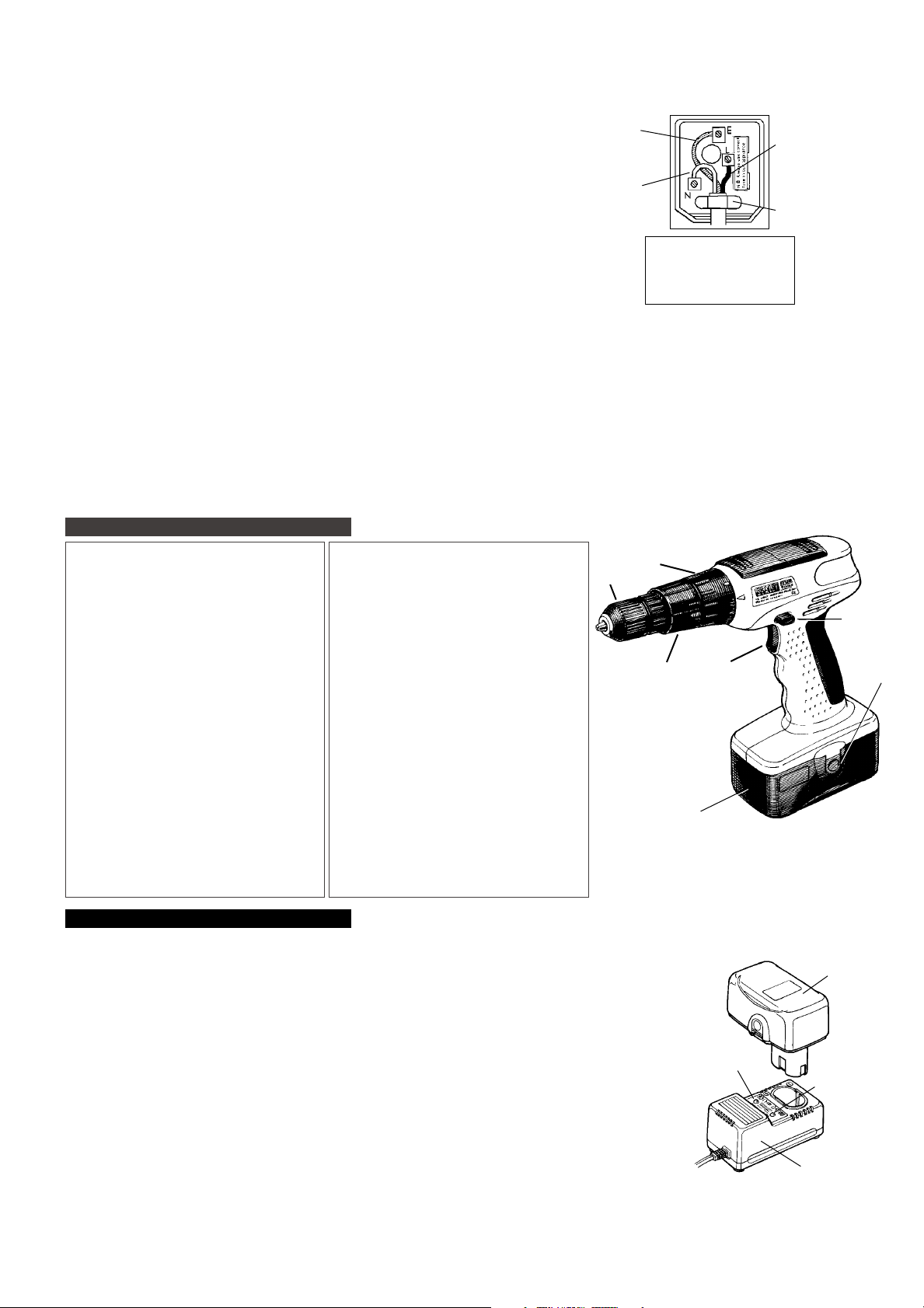
1. Keyless chuck
2. Electronic variable speed switch
3. Lock, reverse and forward switch
4. 12V Battery pack
5. 24-step torque control ring
6. Hammer selector
7. Battery release button (one each side)
Fig.2
1. Battery charger & mains cable
Fig.1
1. Keyless chuck
2. Electronic variable speed switch
3. Lock, reverse and forward switch
4. 18V Battery pack
5. 24-step torque control ring
6. Hammer selector
7. Battery release button (one each side)
Fig.2
1. Battery charger & mains cable
3. OPERATING INSTRUCTIONS
Note: When new, the battery pack will have been shipped in a low charge state. It will take longer to charge initially, and several subsequent charges
may also take a little longer than when the battery pack reaches its optimum performance.
3.1. CHARGING THE BATTERY PACK
3.1.1. To remove the battery pack from the drill, depress the two side release clips (fig.1. 7).
p WARNING! Do not touch the metal terminals.
3.1.2. Place drill in carrying case and remove the battery charger.
3.1.3. Insert the mains power lead into the power socket in the side of the battery charger, and stand
on a safe flat surface. DO NOT connect to the mains at this point.
3.1.4. The battery pack and charger have the positive (+) and negative (-) terminals marked. Align the
correct terminals and insert the battery (fig.2). Note: the battery pack is designed so that it will
only enter the charger unit the correct way. When placed in the charger, a very slight downward
pressure will seat the pack firmly into the power terminals.
3.1.5. When securely in place, plug into mains power and switch on. The red light will glow indicating
that the charge cycle has started.
3.1.6. The red light will remain on until the battery pack is fully charged when it will go out and the green
light will go on. Under normal conditions the battery will take up to 1 hour to fully charge.
3.1.7. When the green light comes on, switch off and unplug the charger from the mains and remove the battery pack.
3.1.8. Place the charger and mains lead in the carry case. Insert the battery pack into the drill, ready for use.
Note: Attempting to recharge a battery pack immediately after use may result in the red charge light not coming on. In such a case allow the
battery to cool for a time and try again.
fig. 2
1.4. BATTERY CHARGER SAFETY INSTRUCTIONS.
pWARNING! DO NOT attempt to charge any battery other than that supplied for the drill. Other types of batteries may explode!
3All mains electrical supply safety features must be followed as described in 1.3. above.
3Disconnect the charger from the mains power supply when not in use.
7DO NOT expose the charger to damp or wet conditions.
7DO NOT pull or carry the charger by the power lead.
7DO NOT operate the charger if it has been dropped, or has received a sharp knock, or is damaged. Take charger to an authorised agent.
7DO NOT dismantle the charger as this may cause damage or personal injury and will invalidate your warranty.
7DO NOT insert foreign objects or material into the hole reserved for the battery pack.
7DO NOT recharge a second battery pack immediately after charging the first. Consecutive charging will overheat the charger. Allow the unit
to cool for 15 minutes before charging the next pack.
7DO NOT attempt to connect two chargers together.
3Store the charger in the same manner as battery pack in 1.2.
Cable clamp
FUSE RATING
THE PLUG FITTED TO PRODUCT
MUST BE EQUIPPED WITH A
3 Amp FUSE
CP9512VHKL & CP9518VHKL - 1022 - (1) - 090699
*Operating capacity is approximate and will
depend on material, drill sharpness,
drill/screw diameter etc.
Full battery capacity will only be achieved
after several charges.
Operating capacity on one full charge*
Drilling - wood . . . .103 holes x 20mm deep
metal . . . . 3 holes x 16mm deep
concrete . . .6 holes x 16mm deep
Screw-driving - . . .110 screws x 30mm long
Operating capacity on one full charge*
Drilling - wood . . . .122 holes x 28mm deep
metal . . . . 5 holes x 18mm deep
concrete . .29 holes x 14mm deep
Screw-driving - . . .182 screws x 30mm long
Red -
charging
indicator
Green -
fully charged
indicator
7
1
2
3
4
5
6
1
4


