2. INTRODUCTION & SPECIFICATION
3.1. Air Supply
pWARNING! Ensure the air supply is clean and does not exceed 90 psi while operating the drill.
Too high an air pressure and unclean air will cause excessive wear, and may be dangerous, causing
damage and/or personal injury.
3.1.1. Ensure the drill air valve (or trigger) is not depressed before connecting to the air supply.
3.1.2. You will require an air pressure between 70-90psi, and an air flow according to the specification above.
3.1.3. Drain the air tank daily. Water in the air line will damage the drill and invalidate your warranty.
3.1.4. Clean air inlet filter weekly. Recommended hook-up procedure is shown in fig 1.
3.1.5. Line pressure should be increased to compensate for unusually long air hoses (over 8 metres).
The minimum hose diameter should be 1/4 I.D. and fittings must have the same inside dimensions.
3.1.6. Keep hose away from heat, oil and sharp edges. Check hoses for wear, and make certain that
all connections are secure.
3.2. Couplings
Vibration may cause failure if a quick change coupling is connected
directly to the air drill. To overcome this, connect a leader hose -
Sealey model number AH2R or AH2R/38 - to the drill. A quick
change coupling may then be used to connect the leader hose to the air line
recoil hose. See figs. 1 & 2.
p
p
WARNING! Disconnect drill from air supply before changing drill bit, servicing or performing maintenance.
Replace or repair damaged parts. Use genuine parts only. Unauthorised parts may be dangerous and will
invalidate the warranty.
5.1. Lubricate the drill daily with a few drops of good grade air tool oil, such as Sealey ATO/500 or
ATO/1000, dripped into the air inlet before use or dispensed automatically through an air system oiler, such
as Sealey model SA100L or SA1/L.
5.2. Clean the drill after use and change the bit when worn or damaged.
5.3. Loss of power or erratic action may be due to the following:
a) Excessive drain on the air supply. Moisture or restriction in the air line. Incorrect size or type of hose
connectors. To remedy check the air supply and follow instructions in Section 3.
b) Grit or gum deposits in the grinder may also reduce performance. Flush the grinder with gum solvent
oil or an equal mixture of SAE No 10 oil and kerosene. Allow to dry before use.
If you continue to experience problems, contact your local Sealey service agent.
5.4. For a full service contact your local Sealey service agent.
5.5. When not in use, disconnect from air supply, clean drill and store in a safe, dry, childproof location.
3. PREPARING DRILL FOR USE
4. OPERATING INSTRUCTIONS
5. MAINTENANCE
p
p
WARNING! Ensure you read, understand and apply safety instructions before use.
4.1 DRILL BIT FITTING. Regularly check the drill bit and always change if worn, cracked or otherwise damaged.
p
p
WARNING! Unplug from the air supply before placing bit into chuck.
4.1.2 Open or close the chuck jaws to a point where the opening is slightly larger than the drill or tool bit (fig 3 A)
to be used. Also raise the front of the drill slightly to prevent bit from falling out of the chuck jaws. Insert
the drill bit into the chuck as far as it will go. Place the chuck key in one of the chuck holes and tighten
the chuck securely.
pWARNING! Ensure you remove the chuck key before starting the drill.
4.2. Connect air supply to drill. Squeeze the trigger to check that the drill is
working correctly before starting work.
4.2.1 DO NOT allow drill to run freely for an extended period of time as this will shorten
the life of bearings.
4.3. STANDARD DRILLING INSTRUCTIONS.
p
p
WARNING! Ensure you wear approved safety goggles and any other safety items required for the job.
Remove the chuck key before using the drill. Also ensure that all other safety requirements are followed.
4.3.1. Connect drill to air supply.
fig. 1
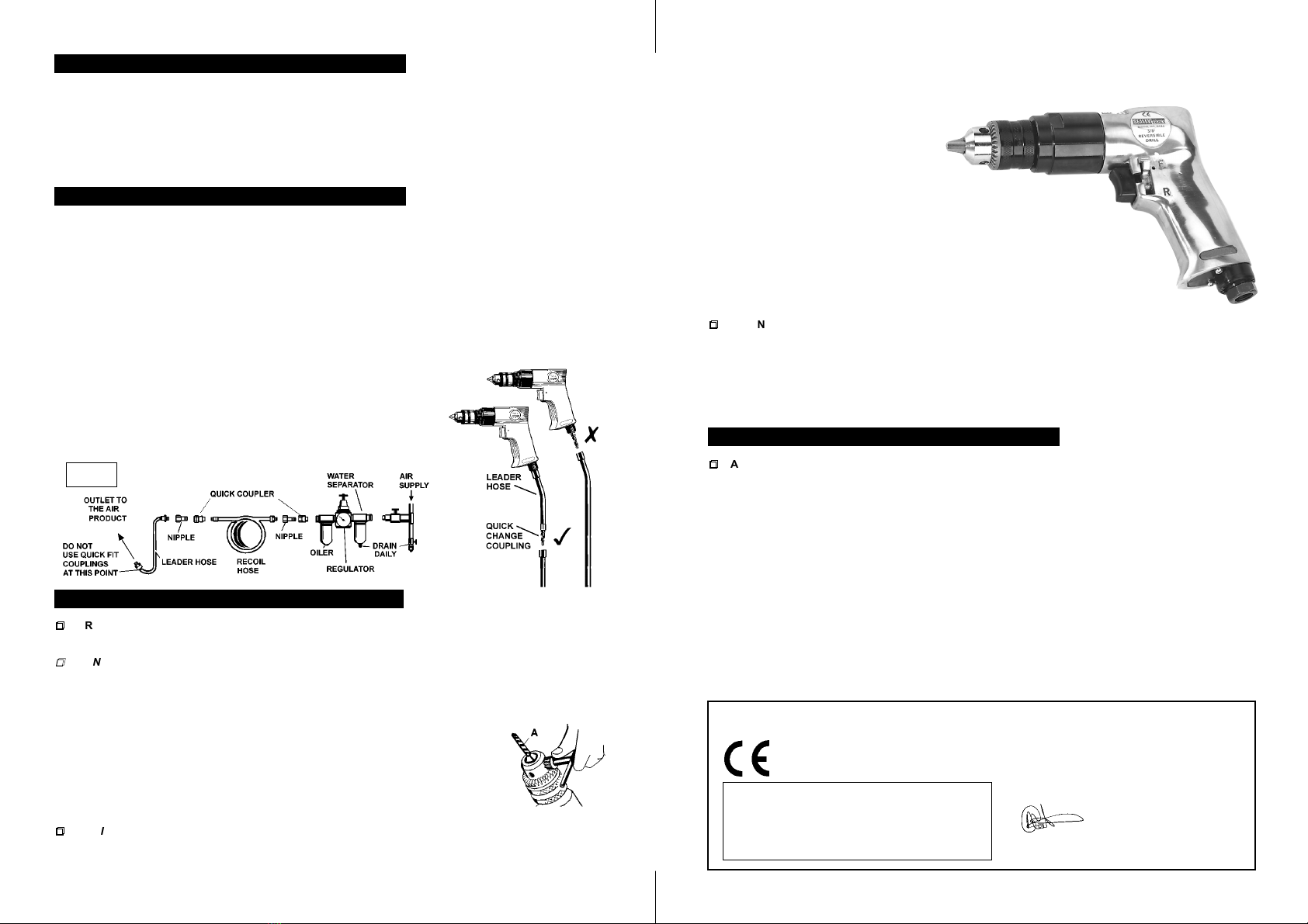
Free Speed . . . . . . . . . . . . . . . . . .1800rpm
Operating Pressure . . . . . . . . . . . . . . .90psi
Air Consumption . . . . . . . . . . . . . . . . .4cfm
Air Inlet . . . . . . . . . . . . . . . . . . . . .1/4BSP
The SA24 is suitable for general workshop use and has a polished and well balanced aluminium body with precision
planetary gears giving quiet and smooth operation. Features reversible action making this tool suitable for driving
and undoing fixings. Fitted with 3/8 drill chuck and supplied with a chuck key.
We, the sole importer into the UK, declare that the product listed here is in conformity with the
following standards and directives. The construction file for this product is held by the
Manufacturer and may be inspected, by a national authority, upon request to Jack Sealey Ltd.
For Jack Sealey Ltd. Sole importer into the UK
of Sealey Power Tools.
REVERSIBLE 3/8 AIR DRILL
Model: SA24
98/37/EC Machinery Directive
93/68/EEC Marking Directive
29th August 2002
Declaration of Conformity
Signed by Mark Sweetman
Sound Pressure . . . . . . . . . . . . . .94.7dB(A)
Vibration . . . . . . . . . . . . . . . . . . . . . .2.5m/s2
Weight . . . . . . . . . . . . . . . . . . . . . . . . .0.9kg
Chuck Size . . . . . . . . . . . . . . . . . . . . . . .3/8
fig. 2
SA24 - (1) - 290802 SA24 - (1) - 290802
4.3.2. Ensure the drill is turning in the forward direction by checking that the lever adjacent to the trigger is
next to the forward symbol (F). If not, push the lever over to the forward position.
4.3.3. Hold tool firmly and place the bit tip to the point to be drilled.
4.3.4. Depress the trigger to start drill. Move the drill bit into the work piece
applying only enough pressure to keep the bit
cutting. DO NOT force or apply side
pressure to elongate the hole.
4.3.5. If the material to be drilled is free
standing it should be secured in a vice
or with clamps to keep it from turning as the
drill bit rotates.
4.3.6. When drilling metals, use a light oil on the drill bit to keep it from
overheating. Oil will prolong life of bit and improve the drilling action.
4.3.7. For hard smooth surfaces use a centre punch to mark desired hole location.
This will prevent bit from slipping as your start to drill.
4.3.8. A pilot hole may be necessary to assist the final drill size through the work piece.
Lock a pilot drill (smaller size drill than the finished hole size) into the chuck. Follow
steps 4.3.1. to 4.3.3. above and drill a pilot hole in the middle of the centre punch mark
where final hole is to be drilled. Insert the final sized bit in chuck. Hold drill firmly and
place the bit at the entrance of the pilot hole and depress the trigger.
p
p
WARNING! Be prepared for drill binding or break through. When these situations occur the drill has a
tendency to grab and kick in the opposite direction which could cause loss of control. If you are not
prepared, this loss of control can result in damage and/or personal injury.
4.3.9 If the bit jams in the workpiece or if the drill stalls, release the trigger switch immediately. Remove
the bit from the workpiece and determine the reason for jamming. It may be necessary to reverse the
direction of rotation by moving the lever adjacent to the trigger to the reverse (R) position.
fig 3