Sealey SM2503 User manual

Refer to
instruction
manual
Wear eye
protection
Wear ear
protection
Wear
protective
clothing
INSTRUCTIONS FOR:
MULTI FUNCTION MACHINE
MODEL NO: SM2503
1. SAFETY
1.2 GENERAL SAFETY
WARNING!Disconnect the multi function machine from the mains power, and ensure the cutting tool or chuck is at a complete standstill before attempting
to change accessories, service or perform any maintenance.
Maintain the multi function machine in good condition (use an authorised service agent).
Replace or repair damaged parts. Use recommended parts only. Unauthorised parts may be dangerous and will invalidate the warranty.
Locate the multi function machine in a suitable area. Ensure the surface is flat and firm. Keep area clean and tidy and free from unrelated materials, and
ensure there is adequate lighting.
Keep the multi function machine clean for best and safest performance and check moving parts alignment regularly.
WARNING! Before each use check that drill/chuck/cutting tool is secure and that it is not worn or damaged. If worn or damaged replace immediately.
WARNING! Keep guard and holding fixings in place, tight and in good working order. Check regularly for damaged parts.
A guard, or any other part, that is damaged must be replaced with a new one, to ensure that it operates properly and performs its intended function, before the tool is
used. The safety guard is a mandatory fitting where multi function machine is used in premises covered by the Health & Safety at Work Act.
Remove adjusting keys and wrenches from the machine and its vicinity before turning it on.
WARNING! Wear approved safety eye protection and, if oil mist is generated, respiratory protection.
Remove ill fitting clothing. Remove ties, watches, rings and other loose jewellery and contain long hair.
Keep hands and body clear of the work table when operating the multi function machine.
Maintain correct balance and footing. Ensure the floor is not slippery and wear non-slip shoes.
Always clamp workpiece securely to the table or hold securely in a vice which is firmly mounted to the table. NEVER hold a workpiece by hand. Ensure that
workpieces to be turned are held securely in the chuck. Long workpieces should be held at both ends and along their length with suitable steady rests.
Keep children and unauthorised persons away from the working area.
WARNING! DO NOT switch the multi function machine on whilst the drill or cutting tool is in contact with the workpiece. Bring the drill or cutting tool gradually
to the workpiece. Avoid un-intentional starting of the multi function machine.
DO NOT force the multi function machine to achieve a task it was not designed to perform.
DO NOT allow untrained persons to operate the multi function machine.
DO NOT get the multi function machine wet or use in damp or wet locations or areas where there is condensation.
WARNING! DO NOT use multi function machine where there are flammable liquids, solids or gases such as petrol, paint solvents, waste wiping rags etc.
DO NOT operate the multi function machine if any parts are missing or damaged as this may cause failure and/or possible personal injury.
DO NOT remove the safety guard whilst in use.
DO NOT attempt to remove a workpiece until the drill, cutting tool or chuck has stopped rotating.
DO NOT touch the workpiece close to the cut as it will be very hot. Allow to cool.
DO NOT leave the drill or cutting tool operating unattended.
DO NOT operate the drill or cutting tool when you are tired or under the influence of alcohol, drugs or intoxicating medication.
When not in use switch the drilling/milling machine off and isolate from the power supply.
1.1. ELECTRICAL SAFETY
WARNING! It is the responsibility of the owner and the operator to read, understand and comply with the following: You must check all electrical products,
before use, to ensure that they are safe. You must inspect power cables, plugs, sockets and any other connectors for wear or damage. You must ensure that the
risk of electric shock is minimised by the installation of appropriate safety devices. A Residual Current Circuit Breaker (RCCB) should be incorporated in the main
distribution board. We also recommend that a Residual Current Device (RCD) is used. It is particularly important to use an RCD with portable products that are
plugged into a supply which is not protected by an RCCB. If in any doubt consult a qualified electrician. You may obtain a Residual Current Device by contacting
your Sealey dealer. You must also read and understand the following instructions concerning electrical safety.
1.1.1. The Electricity at Work Act 1989 requires all portable electrical appliances, if used on business premises, to be tested by a qualified electrician, using
a Portable Appliance Tester (PAT), at least once a year.
1.1.2. The Health & Safety at Work Act 1974 makes owners of electrical appliances responsible for the safe condition of those appliances and the safety of
the appliance operators. If in any doubt about electrical safety, contact a qualified electrician.
1.1.3. Ensure that the insulation on all cables and on the appliance is safe before connecting it to the power supply. See 1.1.1.
and 1.1.2. and use a Portable Appliance Tester.
1.1.4. Ensure that cables are always protected against short circuit and overload.
1.1.5. Regularly inspect power supply cables and plugs for wear or damage and check all connections to ensure that none is loose.
1.1.6. Important: Ensure that the voltage marked on the appliance matches the power supply to be used and that the
1.1.7. DO NOT pull or carry the appliance by the power cable.
1.1.8. DO NOT pull the plug from the socket by the cable.
1.1.9. DO NOT use worn or damaged cables, plugs or connectors. Immediately have any faulty item repaired or replaced by a
qualified electrician.
When a BS 1363/A UK 3 pin plug is damaged, cut the cable just above the plug and dispose of the plug safely.
Fit a new plug according to the following instructions (UK only).
a) Connect the GREEN/YELLOW earth wire to the earth terminal ‘E’.
b) Connect the BROWN live wire to the live terminal ‘L’.
c) Connect the BLUE neutral wire to the neutral terminal ‘N’.
d) After wiring, check that there are no bare wires, that all wires have been correctly connected,
that the cable outer insulation extends beyond the cable restraint and that the restraint is tight.
1.1.10. If an extension reel is used it should be fully unwound before connection. A reel with an RCD fitted is preferred since any appliance plugged into it will
be protected. The cable core section is important and should be at least 1.5mm², but to be absolutely sure that the capacity of the reel is suitable for this
product and for others which may be used in the other output sockets, we recommend the use of 2.5mm² section cable.
Original Language Version SM2503 Issue: 3 - 18/07/17
Replacement fuse
rating: 5A
IMPORTANT: PLEASE READ THESE INSTRUCTIONS CAREFULLY. NOTE THE SAFE OPERATIONAL REQUIREMENTS, WARNINGS & CAUTIONS. USE THE PRODUCT
CORRECTLY AND WITH CARE FOR THE PURPOSE FOR WHICH IT IS INTENDED. FAILURE TO DO SO MAY CAUSE DAMAGE AND/OR PERSONAL INJURY AND WILL
INVALIDATE THE WARRANTY. KEEP THESE INSTRUCTIONS SAFE FOR FUTURE USE.
Thank you for purchasing a Sealey product. Manufactured to a high standard, this product will, if used according to these
instructions and maintained properly, give you years of trouble free performance.
© Jack Sealey Limited

Bench mounting, multifunction mini drill, mill and lathe with variable speed giving flexibility to handle most materials. Features two 150W motors,
one to operate the drill/mill and the other to power the lathe. The lathe cutting feed can be power driven or advanced manually. Thread cutting
may also be undertaken with the optional thread cutting kit. Supplied with Metric graduated scales and all necessary tools required for setting
and adjusting. An optional stand is available, order Model No. SM3002ST.
2. INTRODUCTION & SPECIFICATION
4. OPTIONAL ACCESSORIES
Specification ( Cutting )
Swing over bed............................. 140mm
Distance between centres .................... 250mm
Spindle hole taper ............................ MT2
Cross slide travel ............................ 61mm
Tailstock taper ............................... MT1
Spindle speed (variable)................100 to 2000rpm
Range of metric threads.......5 pitches ( 0.5 to 1.25mm)
Specification ( Drilling )
Max drilling/milling capacity .................... 10mm
Travel of drilling/milling spindle ................. 30mm
Drilling/milling spindle speed ........... 100 to 1300rpm
T-slot....................................... 8mm
Output power ................................150W
Net/gross weight............................40/50kg
Distance from spindle to table ................. 180mm
Distance from spindle centre to column front...... 100mm
3. CONTENTS & ASSEMBLY
Contents: ( Not illustrated )
Mini drilling/milling/cutting machine.
1. ‘C’ Wrench (28/32mm)
2. Drill chuck and taper shank
3. Drill chuck key
4. 3 Hex keys (3,4,6mm)
5. Double ended spanner 8-10
6. Lathe chuck key.
7. 3 External chuck jaws
8. 8mm ‘T’ nuts
9. Fuse
10. Tailstock centre
fig. 2
STEADY REST FOLLOW REST QUICK VICE (50mm) MILL CHUCK SET (MT2)
SM2503SR SM2503FR SM2503QV SM2503MCSET (3,4,5,6,8,10diam.)
2 FLUTE HSS END MILL SET COLLET SET (MT2) INDEXABLE CARBIDE END MILL
SM2503EMSET (3,4,5,6,8,10 diam.) SM2503CSET (3,4,5,6,8,10 diam.) SM2503ICEM(16mm MT2 )
METRIC THREAD CUTTING KIT TAILSTOCK CHUCK+SHANK ROLLING CENTRE HEADSTOCK CENTRE
SM2503TCK (40,42,45,48,50,54,60) SM2503TC ( MT1 10mm ) SM2503RC ( MT1 ) SM2503HC ( MT2 )
TOOL HOLDER SET(Cut off type, 70 x 2 x 10mm) CUT OFF TOOL & BORING TOOL FACEPLATE ( Diam.112mm )
SM2503THSET (Boring cutter, diam.10mm ) SM2503COBT SM2503FP ( ‘T’ slot 8mm )
WARNING! At least two people will be required
to move the machine. Observe good lifting practice.
3.1. Unpack the product and check that all
components and tools are present and
undamaged. If any problem is noted contact your
supplier immediately.
3.2 The machine has been coated with heavy grease
to protect it in shipping. Remove the coating with
commercial degreaser, kerosene or similar
solvent before operating. Avoid getting the
solvent on rubber parts. After degreasing coat
the machined surfaces with a medium consistency machine oil.
3.3 Mounting the machine. Locate the machine on a flat, level and strong work surface. Do not locate in direct sunlight or where heavy
dust or moisture is present.
3.4 Drill the location holes in accordance with the dimensions shown in fig.2 and bolt the machine to the bench using three M6 nuts and
bolts. ( Not provided.)
fig. 1
Original Language Version SM2503 Issue: 3 - 18/07/17
© Jack Sealey Limited

It is assumed that the operator has some experience of machining practice and therefore these instructions are intended only to
describe the features of the machine. If you have no experience of machining it is recommended that you undertake a training
course or seek advice from an experienced source.
WARNING! Before operating the drilling/milling machine ensure you are wearing approved
safety goggles and gloves to protect you from swarf and metal particles. If using cutting oil or
coolant a face mask may be necessary to avoid breathing any vapour generated. Ensure that
all other safety instructions in chapter 1 are followed carefully.
5.1 SETTING UP FOR MILLING. ( Disconnect the machine from the power supply whilst
setting up.) The machine is supplied without milling attachments. Contact your local Sealey
dealer for a full range of accessories.
5.2 Mounting the Cutting Tool. If the drill chuck and arbor are currently mounted, remove them
by the following method. Access the arbor bolt by pulling off the plastic cap ( See fig.4-1 )
which covers the top of the spindle shaft and place an 8mm spanner onto the flats at the top
of the shaft. Insert a rod into the hole in the side of the spindle shaft ( See fig.4-4 ) to prevent
it turning and loosen the arbor bolt by two turns. Give the arbor bolt a sharp tap with a rubber
mallet in order to release the arbor from the internal taper. Continue to unscrew the arbor bolt
by hand whilst supporting the drill chuck and arbor until they become loose and can be
removed.
5.2.1 Select the cutting tool for the work in hand and the appropriate arbor or collet.
Wear protective gloves at all times especially when handling the cutter. Introduce the
cutter assembly into the spindle sleeve and hold it in place whilst the arbor bolt is tightened
by hand. Insert a rod into the hole in the side of the spindle shaft to prevent the spindle
rotating and tighten the arbor bolt with a spanner ( do not overtighten ).
Remove the rod and replace the plastic cap.
5.3 Attaching the workpiece. The workpiece will be mounted to the crossfeed table utilising the
8mm ‘T’ slots provided for the tool rest.
5. SET- UP AND OPERATION
fig. 3
fig.4
1
3
4
5
2
Original Language Version SM2503 Issue: 3 - 18/07/17
© Jack Sealey Limited

5.4 Setting and locking the cutter height. Once the workpiece and cutter are mounted, the cutter can be lowered to the correct position
to achieve the desired cut. The spindle shaft vertical movement is 30mm. If this does not bring the cutter into the vicinity of the
workpiece the whole head can be moved down the column to achieve the desired cutter position. Adjust cutter and head height as
described below. To ensure accuracy during milling the cutter height setting must then be locked as described below.
5.5 Setting the head height. The overall height of the head on the column can be altered by using the head vertical feed wheel ( see
fig.4-2 ). To alter the head height first loosen the two socket cap bolts adjacent to the vertical leadscrew ( see fig.4-3 ). Use the
handwheel to move the head to the desired height and tighten the socket cap screws to lock the head in position.
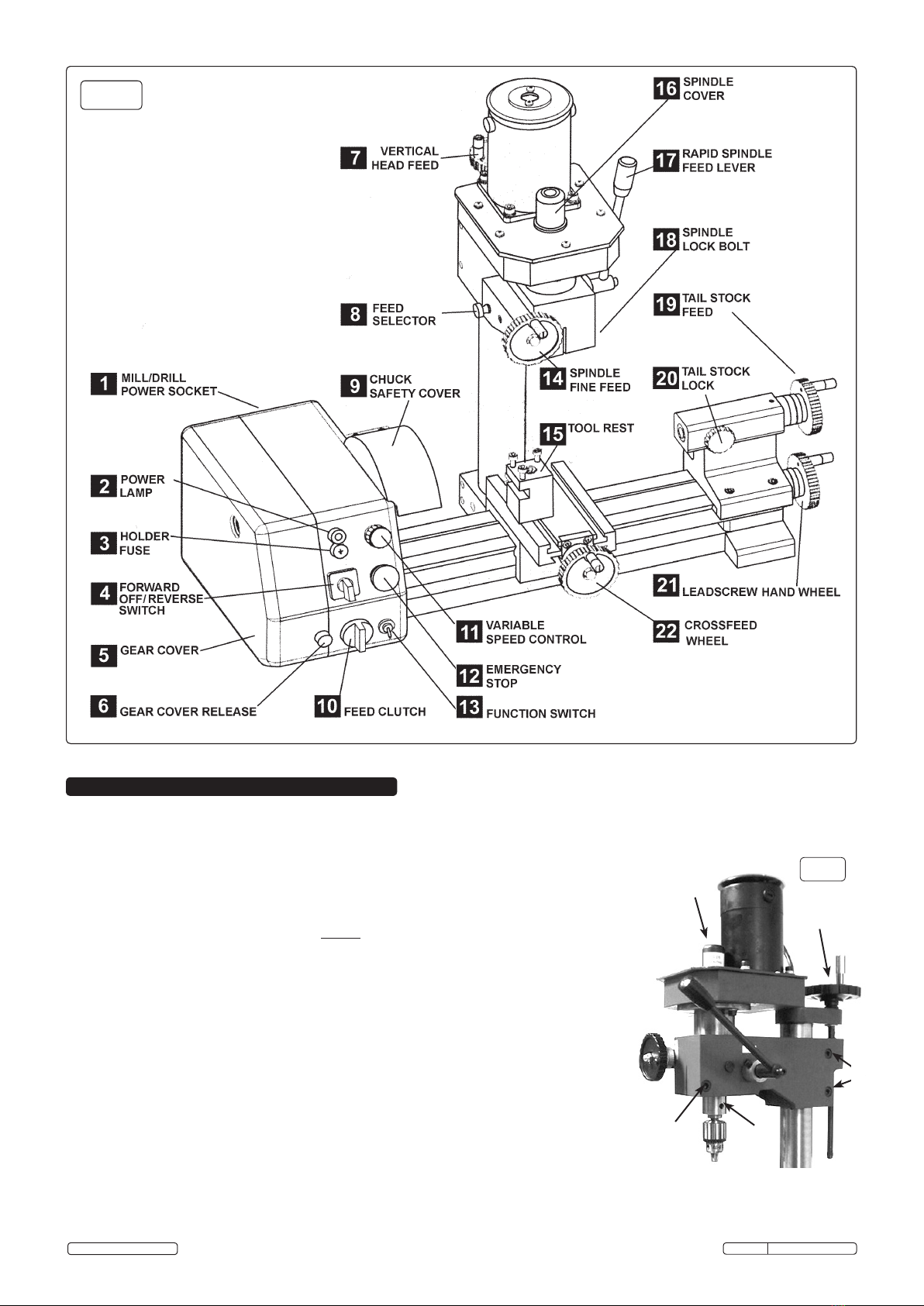
5.6 Engaging vertical fine feed. The drilling/milling spindle travel is controlled for milling purposes by the fine feed wheel ( see fig.3-14 ).
To engage the fine feed wheel push the feed selector knob ( see fig.3-8 ) inwards. This action automatically disengages the rapid
spindle feed lever ( see fig.3-17 ). Once the spindle/cutting tool has been moved to the correct height it can be locked in this position
by tightening the socket cap bolt on the right hand side of the head ( see fig.4-5 ).
5.7 Calibrated feed. Each feed wheel has an adjustable calibration ring situated on the feed shaft immediately behind the wheel. The
rings can be rotated by hand and set to an adjacent mark in order to execute a cut of a specific depth.
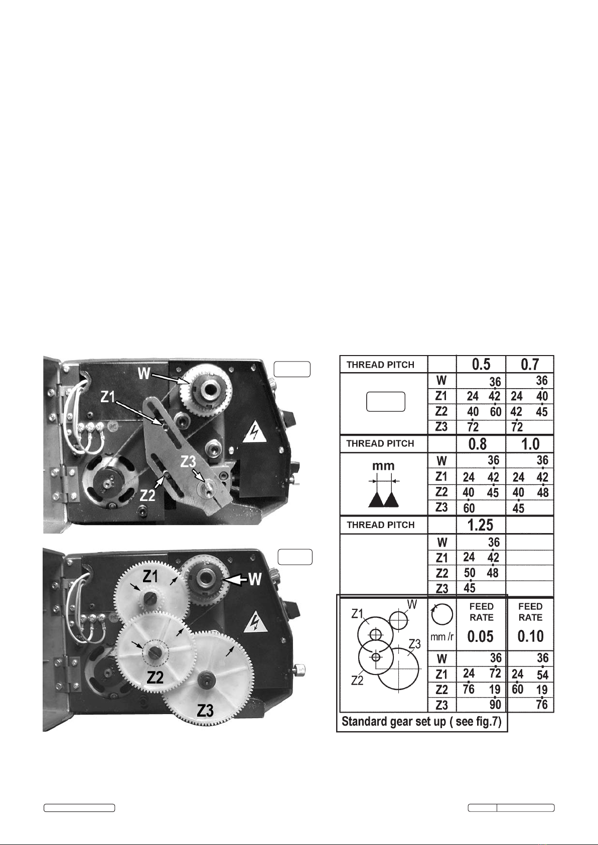
5.7.1 The longitudinal feed ring has 31 divisions to one full rotation of the wheel. One segment represents a movement of 0.05mm.
The cross feed ring has 50 divisions to one full rotation of the wheel. One segment represents a movement of 0.025mm.
The longitudinal feed ring has 36 divisions to one full rotation of the wheel. One segment represents a movement of 0.05mm.
5.8 Main ON/OFF switch with speed control and emergency shut off.
5.8.1 The function switch ( see fig.3-13 ) allows you to select either milling/drilling or cutting on the lathe. The switch has a central OFF
position. Set the switch to milling/drilling.
5.8.2 Select the direction of rotation ( forward for milling/drilling ) using the forward/OFF/reverse switch ( see fig.3-4 ).
5.8.3 Ensure that the variable speed control ( see fig.3-11 ) is set at ‘0’ otherwise the machine will not start.
5.8.4 Connect the machine to the mains power supply. The green power lamp ( see fig.3-2 ) will illuminate.
5.8.5 If the light does not illuminate release the emergency off switch by twisting the button clockwise until it jumps up.
5.8.6 Rotate the rotary speed switch slowly clockwise. As the knob is turned a click will be heard and the motor will start. As the knob is
turned further the speed will increase. Set the knob to the desired speed.
5.8.7 Stop modes. There are three ‘stop’ modes as described below.
(A). To stop the machine for a short while and then restart, simply return the rotary speed switch to the ‘0’ position. When you are
ready to restart, rotate the switch clockwise to the desired speed.
(B) If the machine is to be left unattended for any length of time, switch the forward/reverse switch to ‘OFF’ as well as returning the
speed switch to ‘0’.
(C) In an emergency hit the large red emergency button which automatically cuts the electrical supply to the machine. Before the
machine will start again the rotary speed switch must be returned to the ‘0’ position and the emergency switch must be released.
6.1 SETTING UP FOR DRILLING.( Disconnect the machine from the power supply while setting up.)
6.2 Engaging rapid drill feed. The rapid drill feed is controlled with the lever on the right hand side of the head. ( See fig.3-17 ) The rapid
drill feed will not operate if the vertical fine feed wheel used for milling is still engaged. To make the rapid drill feed operative pull the
feed selector knob outwards. ( See fig.3-8 )
6.3 Mounting the chuck and arbor. If the milling cutter and arbor are currently mounted, remove them by loosening the arbor bolt by two
turns and giving it a tap with a rubber mallet. Access the arbor bolt by pulling off the plastic cap which covers the top of the spindle
shaft and place an 8mm spanner onto the flats at the top of the shaft. Insert a rod into the hole in the side of the spindle shaft ( See
fig.4-4 ) to prevent it turning and loosen the arbor bolt by two turns. Give the arbor bolt a sharp tap with a rubber mallet in order to
release the arbor from the internal taper. Continue to unscrew the arbor bolt by hand whilst supporting the milling cutter and arbor until
they become loose and can be removed. ( Wear protective gloves.) Insert the chuck arbor into the bottom of the spindle shaft and
retain it with the arbor bolt. Do not over tighten. The drill chuck is a shallow taper fit onto the end of the drilling arbor. Using the chuck
key open the jaws of the chuck until they withdraw inside the chuck body. Place a piece of wood onto the cross feed bed and position
the chuck on it below the spindle shaft. Using the drill feed, wind the spindle shaft down until the arbor enters the chuck. Exert firm but
not excessive downward pressure on the chuck to retain it on the arbor.
6.4 Drill bits. Insert an appropriate drill bit into the chuck and tighten the chuck with the chuck key. Remove the chuck key.
6.5 Attaching the workpiece. The cross feed bed of the machine has 2 inverted 8mm ‘T’ slots in it for fixing the workpiece or any
vice/clamping arrangement used to hold the workpiece.
6.6 Altering the height of the head. If the tip of the drill bit is not close enough to the workpiece alter the height of the head on the
column as described in section 5.4.
6.7 Speed control and ON/OFF operation. Refer to Section 5.7 for the operation of the main ON/OFF switch and speed setting.
6.8Avoid subjecting drills and cutting tools to excessive strain. Do not apply undue force on the handle in order to cut the workpiece.
Maintain a controlled cutting speed through the workpiece.
7.1 SETTING UP FOR CUTTING ON THE LATHE. ( Disconnect the machine from the power supply while setting up.)
7.2 The chuck. The chuck is attached to the faceplate with 3 studs and nuts. Check that these fixings are secure before proceeding. The
chuck is provided with two sets of jaws for either external or internal holding of objects to be turned. Select and fit the appropriate
jaws. Using the chuck key wind out the jaws to their maximum extent at which point they can be pulled out by hand. The thread
segments are staggered differently on each jaw and therefore the jaws are numbered 1 to 3. Insert the jaws in sequence beginning
with No1 and in an anti clockwise direction as you face the chuck. Hold them under pressure whilst turning the key until they are
picked up by the mechanism and start to move towards the centre of the chuck. Check that the three jaws come together correctly at
the centre of the chuck. If not, wind the jaws out again and press on the misaligned jaw until it drops into place.
7.3 Tailstock/centre. Material/stock that is too long to be held in the chuck alone can be steadied by a centre fitted into the tailstock.
Once one end of the workpiece is fixed into the chuck loosen the two socket cap screws holding the tailstock and slide it up to the
unsupported end of the workpiece so that the centre is close to it. Tighten the tailstock socket cap screws. Now wind the tailstock
wheel so that the centre makes contact with the end of the workpiece and lock its position by tightening the tailstock lock.( See
fig.3-20 )
7.4 Toolrest. Mount the toolrest utilising the ‘T’ slots in the cross feed table. Insert an appropriate cutting tool into the split carrier and
mount the tool and carrier into one side of the toolrest. Now make any necessary adjustments to the position of the toolrest and
carrier to allow the cutting edge of the tool to be correctly presented to the workpiece. The tool should be cutting in a plane that
passes through the centre axis of the workpiece or just below it.
7.4.1 The angle of the tool when viewed from above may be changed by loosening the central holding bolt on the toolrest and twisting the
whole rest on the bed to obtain the desired angle.
7.4.2 One side of the toolrest will clamp the tool and carrier parallel to the bed of the machine. On the other side of the toolrest the tool and
carrier rests on a contoured block which allows the tool to be inclined upwards or downwards by a few degrees. The angle of tilt is
controlled by adjusting the two socket cap bolts which bear on the tool carrier.
7.5 Adjust the crossfeed wheel and longitudinal feed so that the tip of the tool is in the correct position to commence cutting when the
machine is turned on. Before turning on check that all fixings holding the tool are tight.
Original Language Version SM2503 Issue: 3 - 18/07/17
© Jack Sealey Limited

8.1 Starting the machine. Lower the guard over the chuck. (The machine will not start with the guard in the up position.) Check that the
function switch is set to ‘cutting’.
8.2 Select either manual cutting or automatic feed using the clutch knob. See fig.3-10. ( When selecting autofeed it may be necessary to
rotate the leadscrew hand wheel slightly before the clutch will engage.)
8.3 Select the direction of cut using the forward/reverse switch. When using autofeed ensure that the saddle/cross feed/toolrest are
positioned at the intended start of the cut and that the correct direction has been selected. In general the cut will usually start from the
tailstock direction and progress towards the chuck.
8.4 Turn the machine on using the variable speed control. Rotate the knob clockwise until the desired speed is reached. Refer to section
5.7 for a full description of the on/off operation.
WARNING! The machine should never be left unattended whilst switched on during manual or automatic operation. In particular when
a cut is in progress using autofeed the operator must observe the entire cut and be on hand to switch the machine off as the cutting
tool approaches the chuck or other holding devices. Failure to do this may result in damage to the machine and will invalidate
the warranty.
9.1 Autofeed rate/thread cutting. The machine is supplied with a gear set which gives a cutting rate of 0.05mm per single chuck rotation
when autofeed is selected. ( See fig.7 and the standard gear set up highlighted in the gear ratio table below.) By purchasing the
optional metric thread cutting kit ( Part No.SM2503TCK ) the machine becomes capable of an additional autofeed rate of 0.01mm and
will cut metric thread pitches 0.5/0.7/0.8/0.1&1.25mm as indicated in the gear ratio table.
9.2 Changing gear sets. To set up the machine for a particular thread pitch or feed rate refer to the gear ratio chart for the sizes of Z1,Z2
& Z3 and then identify the actual gears. ( The number of teeth on each gear is moulded into the face of the gear.) Gears Z1 and Z2
are pairs of gears which are a push fit onto a splined sleeve. Ensure that the correct pairs are on the sleeve together according to the
chart.
9.3 Remove the existing gear set. Use a large screwdriver to remove Z1 and then Z2. Use a 4mm hex key to remove Z3. The mountings
for Z1 and Z2 are slotted ( See fig.6 ) to allow the centres of the gears to move to accommodate the differing sizes.
9.4 To assemble the new gear set attach Z3 first and tighten the fixing. As gears Z1 & Z2 overlap attach the ‘hidden’ gear first. The
attachment slots have a sliding nut positioned at the rear of the plate. Slide the nut into the approximate position required. Screw the
gear into place but leave it loose enough to slide. Attach the final gear to the sliding nut in the other slot and allow the gears to settle
into position. When you are satisfied that the gears are fully meshed tighten the fixings for Z1 and Z2. Close and secure the gear
cover and test run the machine to ensure that the drive train is fully functional.
24
72
76
19
90
36
fig. 5
fig. 6
fig. 7
Original Language Version SM2503 Issue: 3 - 18/07/17
© Jack Sealey Limited

Ensure the machine is unplugged from the mains power supply before attempting
any maintenance.
For maximum performance it is essential that the lathe is properly maintained.
10.1. Lubricate the machine before every use. Lubricate the bearings at either end of
the leadscrew once or twice during the day if used continuously. Open the gear
train cover to gain access to the left hand bearing. Inject oil into the compound s
slide oilway located on the slide front surface between the two hex socket cap
screws.
10.2. After each use remove all swarf from the machine and thoroughly clean all
sufaces. If coolant has been used ensure it is all cleaned from the machine and
any collection tray is completely drained. Lightly oil all machined surfaces.
10.3 Clean and coat the leadscrews with oil weekly.
10.4 Cross slide and saddle adjustment. Adjust the accuracy of the cross feed and
saddle on a monthly basis. Any wear or slack can be taken up by adjusting the
position of the appropriate gib strip. To do this use a hex key and spanner as
shown in fig.8. Adjust the cross feed using the adjusters marked ‘A’ in fig.9.
10.5 Loosen the locking nuts on all four adjusters and screw them in evenly using the
same torque. The slide should now be held firmly. Test by trying to turn the handle
but do not force it to turn.
10.6 Now back off each gib screw by a quarter of a turn and tighten the lock nuts. Test again by turning the handle. The
movement should be even and smooth along its whole travel.
10.7 If the movement is too slack, screw all the adjusters in by one eighth of a turn until the correct adjustment is attained.
Tighten the lock nuts.
10.8 Adjust the saddle in the same way using the three adjusters marked ‘B’ in fig.9.
10.9 Cross slide feed handle. If any stiffness occurs in the operation of the handle it is usually as a result of swarf
lodging between the mating surfaces. Remove the handwheel by undoing the securing screw and pull off the
calibrated collar taking care to retain the small spring plate which sits in a groove beneath the collar. Clean the
parts and reassemble in the reverse order taking care to correctly reposition the spring.
10. MAINTENANCE
fig. 8
A
A
A
A
B
B
B
fig.9
Sealey Group, Kempson Way, Suffolk Business Park, Bury St Edmunds, Suffolk. IP32 7AR
01284 757500 01284 703534 sales@sealey.co.uk www.sealey.co.uk
Note: It is our policy to continually improve products and as such we reserve the right to alter data, specifications and component parts without
prior notice.
Important: No Liability is accepted for incorrect use of this product.
Warranty: Guarantee is 12 months from purchase date, proof of which is required for any claim.
WEEE REGULATIONS
Dispose of this product at the end of its working life in compliance with the EU Directive on Waste Electrical and Electronic Equipment
(WEEE). When the product is no longer required, it must be disposed of in an environmentally protective way. Contact your local solid
waste authority for recycling information.
ENVIRONMENT PROTECTION
Recycle unwanted materials instead of disposing of them as waste. All tools, accessories and packaging should be sorted, taken to
a recycling centre and disposed of in a manner which is compatible with the environment. When the product becomes completely
unserviceable and requires disposal, drain any fluids (if applicable) into approved containers and dispose of the product and fluids
according to local regulations.
Parts support is available for this product. To obtain a parts listing and/or diagram, please log on to
www.sealey.co.uk, email sales@sealey.co.uk or telephone 01284 757500
Original Language Version SM2503 Issue: 3 - 18/07/17
© Jack Sealey Limited

EC DECLARATION
OF CONFORMITY
Description and Function:������������������������������������������������������������������������������������������������������������������������������������������������������������������������
Model/Type:���������������������������������������������������������������������������������������������������������������������������������������������������������������������������������������������
Manufacturing Date/Serial Number where applicable: ����������������������������������������������������������������������������������������������������������������������������
This declaration of conformity is issued under the sole responsibility of the manufacturer:
Jack Sealey Ltd, Kempson Way, Suolk Business Park, Bury St Edmunds, Suolk. IP32 7AR
Declaration of Conformity in accordance with the above Directive(s)�
Technical le compiled by: Jack Sealey Ltd
Being the responsible person appointed by the manufacturer.
Signed�������������������������������������������������������������������������������������������
Date�����������������������������������������������������������������������������������������������
Name���������������������������������������������������������������������������������������������
Position�����������������������������������������������������������������������������������������
Place: Bury St Edmunds
Mini Lathe & Drilling Machine
SM2503 v1
2014/35/EU Low Voltage Directive
2014/30/EU EMC Directive
2012/19/EU WEEE Directive
2011/65/EU RoHS Directive
2006/42/EC Machinery Directive
References to harmonised standard(s)
EN 60204-1:2006+AC:2010 ���������������������������������������������������������
EN 23125:2010+A1:2012 �������������������������������������������������������������
EN 61000-6-2:2005 ����������������������������������������������������������������������
EN 61000-6-4:2007+A11:2011 �����������������������������������������������������
������������������������������������������������������������������������������������������������������
������������������������������������������������������������������������������������������������������
������������������������������������������������������������������������������������������������������
������������������������������������������������������������������������������������������������������
������������������������������������������������������������������������������������������������������
������������������������������������������������������������������������������������������������������
������������������������������������������������������������������������������������������������������
������������������������������������������������������������������������������������������������������
17 July 2017
Steve Buckle�
Marketing Director�
20172813
Sealey Group, Kempson Way, Suffolk Business Park, Bury St Edmunds, Suffolk. IP32 7AR
01284 757500 01284 703534 sales@sealey.co.uk www.sealey.co.uk

Sealey Group, Kempson Way, Suffolk Business Park, Bury St Edmunds, Suffolk. IP32 7AR
01284 757500 01284 703534 sales@sealey.co.uk www.sealey.co.uk
NOTE: It is our policy to continually improve products and as such we reserve the right to alter data, specifications and component parts without prior notice.
IMPORTANT: No liability is accepted for incorrect use of product.
WARRANTY: Guarantee is 12 months from purchase date, proof of which will be required for any claim.
SM2503 Issue 2 21/07/17Page 1 of 5
Parts Information:
Mini Lathe & Drilling Machine
Model No: SM2503

SM2503 Issue 2 21/07/17
Sealey Group, Kempson Way, Suffolk Business Park, Bury St Edmunds, Suffolk. IP32 7AR
01284 757500 01284 703534 sales@sealey.co.uk www.sealey.co.uk
Page 2 of 5
NOTE: It is our policy to continually improve products and as such we reserve the right to alter data, specifications and component parts without prior notice.
IMPORTANT: No liability is accepted for incorrect use of product.
WARRANTY: Guarantee is 12 months from purchase date, proof of which will be required for any claim.
Parts Information:
Mini Lathe & Drilling Machine
Model No: SM2503

SM2503 Issue 2 21/07/17
Sealey Group, Kempson Way, Suffolk Business Park, Bury St Edmunds, Suffolk. IP32 7AR
01284 757500 01284 703534 sales@sealey.co.uk www.sealey.co.uk
Page 3 of 5
Parts Information:
Mini Lathe & Drilling Machine
Model No: SM2503
Item Part No. Description
1 SM. CHANGE GEAR COVER
2 SM. CAP SCREW M4x8
3 SM. CAP SCREW M4x12
4 SM. HINGE L*B=38*31
5 SM. WASHER 4
6 SN.S STEEL NUT M4 ZINC DIN934 (SINGLE)
7 SM. CANTILEVER
8 SM. M6 HALF NUT S/C
9 FWM.SB FLAT WASHER M6 BLACK (SINGLE)
10 SM. COMPRESSION SPRING
11 SM. SPACING RING
12 SM. COVER FOR SPINDLE BOX
-- SM. VARIABLE SPEED CONTROL
-- SM. FEED CLUTCH KNOB
13 SM. ROTATE SPINDLE
14 SM. KEY 3x6
15 SM. PROTECT COVER FOR CHUCK
16 SM. CAP SCREW M4x8
17 SM. CAP SCREW M5x8
18 SM. REAR SPLASH GUARD
19 SM. MOTOR
20 SM. KEY 3x16
21 SM. CHECK RING 8
22 SM. TIMING PULLEY
23 SM. SUPPORT PLATE
24 SM. SCREW M4x8
25 SM. WASHER 6
26 SM. SPRING WASHER 6
27 SM. SCREW M6x20
28 SM. WASHER 8
29 SM. SPRING WASHER 8
30 SM. SCREW M8x20
31 SN.S STEEL NUT M18 ZINC DIN934(SINGLE)
32 SM. SPINDLE GEAR
33 SM. SPACING RING (I)
34 SM. SPINDLE TIMING PULLEY
35 SM. SPACING RING (II)
36 SM. BEHIND OIL SEAL (RING)
37 B/ BEARING 30205
38 SM. SPINDLE BOX
39 SM. FRONT OIL SEAL (RING)
40 SM. KEY 6x36
41 SM. SPINDLE
42 SM. KEY
43 SN.S STEEL NUT M6 ZINC DIN934 (SINGLE)
44 SM. SCREW M6x25
Item Part No. Description
45 SM. CHUCK FLANGE
46 SM. ROUND CAP SCREW M4x12
47 SM. 80mm 3-JAW CHUCK
48 SM. HANDLE SCREW (SET OF 3)
49 SM. SMALL HANDLE
50 SM. HANDWHEEL
51 SN.SD STEEL NUT M6 DOMED (SINGLE)
52 SM. SPRING STEEL
53 SM. DIAL
54 SM. SCREW BASE
55 SM. KEY 2x18
56 SM. TAILSTOCK SCREW
57 SM. SCREW M5x8
58 SCB.SB SOCKET HEAD CAP SCREW M5x20 BLACK
59 SM. TAILSTOCK CASTING
60 SM. WEDGE
61 SM. LOCK HANDLE
62 SM. TAILSTOCK QUILL
63 SM. DIAL
64 SM. SCREW M5x14
65 SM. SCREW BRACKET
66 SM. BED LEAD RAIL
67 SM. LEADSCREW
68 SB. STEEL BALL 6.4mm
69 SM. COMPRESSION SPRING
70 SM. SCREW M6x10
71 SM. PIN 3x14
72 SM. CLUTCH BRACKET
73 SM. CLUTCH
74 SM. KEY 3x22
75 SM. SHAFT
76 SM. KEY 3x14
77 SM. GEAR SHAFT BRACKET
78 SN.S STEEL NUT M5 ZINC DIN934 (SINGLE)
79 SM. SUPPORT PLATE
80 SM. WASHER
81 SM. CHANGE GEAR Z=72
82 SM. CHANGE GEAR Z=19
83 SM. CHANGE GEAR Z=76
84 SM. CHANGE GEAR Z=24
85 SM. GEAR SLEEVE
86 SM. GEAR SHAFT
87 SM. SCREW M5x8
88 SM. SPACING RING
89 SM. CHANGE GEAR Z=90
90 SM. SCREW M5x25

SM2503 Issue 2 21/07/17
Sealey Group, Kempson Way, Suffolk Business Park, Bury St Edmunds, Suffolk. IP32 7AR
01284 757500 01284 703534 sales@sealey.co.uk www.sealey.co.uk
Page 4 of 5
Parts Information:
Mini Lathe & Drilling Machine
Model No: SM2503
Item Part No. Description
91 SM. BED BASE
92 SM. SCREW M6x35
93 SM. UNPLUG SHAFT
94 SM. DAM BOARD
95 SM. SCREW M4x10
96 SM. CLUTCH ROTATE KNOB
97 SM. SCREW M5x12
98 SM. LEADSCREW BRACKET
99 SM. CROSS SLIDE SCREW M4x16
100 SM. SADDLE
101 SM. CROSS SLIDE NUT
102 SM. LEADSCREW NUT
103 SM. CROSS SLIDE
104 SM. SCREW M4x16
105 SN.S STEEL NUT M4 ZINC DIN934 (SINGLE)
106 SM. CROSS SLIDE WEDGE
107 SM. GIB STRIP
108 SCB.SB SOCKET HEAD CAP SCREW M8x40 BLACK
109 SM. TOOL REST
110 SM. TOOL REST SHAFT
111 SM. CONNECT BLOCK
112 SM. POTENTIOMETER
113 SM. EMERGENCY STOP SWITCH
114 SM. FORWARD/OFF/REVERSE SWITCH
115 SM. POWER INDICATOR LIGHT, 220V
116 SM. FUSE BOX
117 SM. PC BOARD
-- SM.N PC BOARD
118 SM. LOCK CONNECT
119 SM. PC BOARD BOX
120 SM. SCREW ST2.9x10
121 SM. MICRO SWITCH
122 SM. SCREW ST1.9x10
123 SM. POWER CORD WITH PLUG
130 SM. SCREW M5x12
131 SM. TIMING BELT
132 SM. FORWARD/OFF/REVERSE SWITCH
133 SM. BOLT M6x55
134 SM. HANDLE SLEEVE
135 SM. HANDWHEEL
136 SM. LEADSCREW BRACKET
137 SM. LIFTER
138 SM. KEY 3x10
139 SM. COLUMN
140 SM. SCREW M6x18
Item Part No. Description
141 SM. PIN 6x24
142 SM. COLUMN BRACKET
143 SM. SCREW M8x50
144 SM. PROTECTING COVER FOR MOTOR
145 SM. SCREW M6x12
146 SM. SPACING RING
147 SM. MOTOR GEAR
148 SM. SPACING RING
149 SM. COVER UP PLATE
150 SM. QUILL FIXED PLATE
151 SM. GEAR BOX
152 SM. SPINDLE QUILL
153 SM. SCREW M6x14
154 SM. BEARING
155 SM. SPINDLE BASE
156 SM. SAFETY COVER
157 SM. CHECK RING 20
158 SM. SPINDLE GEAR (Z=55)
159 SM. SPACING RING
160 SM. ROUND NUT M24x1.5
161 SM. WASHER 24
162 SM. CHECK RING 38
163 SM. COMPRESSION SPRING
164 SM. SPRING SUPPORT
165 SM. HAND SHANK
166 SM. LEVER CAP M8x40
167 SM. READ OUT SLEEVE
168 SM. SPRING PIN 3x12
169 SM. SITE SCREW
170 SM. GEAR SHAFT
171 SM. SPACING RING
172 SM. CONNECT SITE SCREW
173 SM. BEVEL GEAR
174 SM. WORM BASE
175 SM. SCREW M5x18
176 SM. PIN 3x12
177 SM. CONNECT SHAFT
178 SM. PIN 3x18
179 SM. WORM SHAFT
180 SM. DIAL
181 SM. LO CK BO LT
182 SM. KEY 4c12
183 SM. DRILL SPINDLE
184 SM. TAPER SHANK B12
193 SM. POWER SUPPLY SWITCH

SM2503 Issue 2 21/07/17
Sealey Group, Kempson Way, Suffolk Business Park, Bury St Edmunds, Suffolk. IP32 7AR
01284 757500 01284 703534 sales@sealey.co.uk www.sealey.co.uk
Page 5 of 5
NOTE: It is our policy to continually improve products and as such we reserve the right to alter data, specifications and component parts without prior notice.
IMPORTANT: No liability is accepted for incorrect use of product.
WARRANTY: Guarantee is 12 months from purchase date, proof of which will be required for any claim.
Lathe Tools & Accessories
Parts Information:
Mini Lathe & Drilling Machine
Model No: SM2503
Item Part No. Description
A SMCSET COLLET SET MT2-M10 3-10mm dia
B SMEMSET HSS END MILL SET MT2 3-10mm dia
C SMMCSET MILL CHUCK SET MT2-M10 3-10mm dia
-- SMMCSET. "C" SPANNER
D SMICEM INDEXABLE CARBIDE END MILL MT2-M10
16mm dia
E SMQV QUICK VICE 50mm
F SMRC REVOLVING CENTRE MT1
G SMHC LIVE CENTRE MT2
H SMTC TAILSTOCK CHUCK MT1 10mm
I SMTHSET TOOL HOLDER (PARTING & BORE) SET 2pc
Item Part No. Description
J SMCOBT PARTING TOOL & BORE CUTTER SET 2pc
M SMFP FACE PLATE 112mm dia
N SMSR STEADY REST
O SMTCK THREAD CUTTING GEAR KIT METRIC
P SMFR FOLLOW REST
V SMST STAND for SM3002, SM2502, SM2503
-- SM.AT ADJUSTING TOOLS (not shown)
-- SM.ST SETTING TOOLS (not shown)
-- SM.DCK DRILL CHUCK KEY (not shown)
-- SM.LCK LATHE CHUCK KEY (not shown)
Table of contents
Other Sealey Lathe manuals