Sealey SM14.V5 User manual

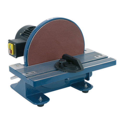
915 X 100MM BELT/Ø150MM DISC SANDER 500W
MODEL NO: SM14.V5
Thank you for purchasing a Sealey product. Manufactured to a high standard, this product will, if used according to these instructions,
and properly maintained, give you years of trouble free performance.
IMPORTANT: PLEASE READ THESE INSTRUCTIONS CAREFULLY. NOTE THE SAFE OPERATIONAL REQUIREMENTS, WARNINGS & CAUTIONS. USE
THE PRODUCT CORRECTLY AND WITH CARE FOR THE PURPOSE FOR WHICH IT IS INTENDED. FAILURE TO DO SO MAY CAUSE DAMAGE AND/OR
PERSONAL INJURYAND WILL INVALIDATE THE WARRANTY. KEEP THESE INSTRUCTIONS SAFE FOR FUTURE USE.
1. SAFETY
1.1. ELECTRICAL SAFETY
WARNING! It is the user’s responsibility to check the following:
9Check all electrical equipment and appliances to ensure that they are safe before using.
9Inspect power supply leads, plugs and all electrical connections for wear and damage.
9Sealey recommend that an RCD (Residual Current Device) is used with all electrical products.
9If the product is used in the course of business duties, it must be maintained in a safe condition and routinely PAT (Portable Appliance
Test) tested.
9Ensure that the insulation on all cables and on the appliance is safe before connecting it to the power supply.
9Regularly inspect power supply cables and plugs for wear or damage and check all connections to ensure that they are secure.
WARNING! Ensure that the voltage rating on the appliance suits the power supply to be used and that the plug is tted with the correct
fuse - see fuse rating in these instructions.
8DO NOT pull or carry the appliance by the power cable.
8DO NOT pull the plug from the socket by the cable.
8DO NOT use worn or damaged cables, plugs or connectors.
9Ensure that any faulty item is repaired or is replaced immediately by a qualied electrician.
9This product is tted with a BS1363/A 3 pin plug.
9If the cable or plug is damaged during use, switch off the electricity supply and remove from use.
9Ensure that repairs are carried out by a qualied electrician.
9Replace a damaged plug with a BS1363/A 3 pin plug. If in doubt contact a qualied electrician.
a) Connect the GREEN/YELLOW earth wire to the earth terminal ‘E’.
b) Connect the BROWN live wire to the live terminal ‘L’.
c) Connect the BLUE neutral wire to the neutral terminal ‘N’.
9Ensure that the cable outer sheath extends inside the cable restraint and that the restraint is tight.
9Sealey recommend that repairs are carried out by a qualied electrician.
1.2. GENERAL SAFETY
WARNING! Ensure all Health and Safety, local authority, and general workshop practice regulations are strictly adhered to.
WARNING! Disconnect from the mains power supply before changing accessories, servicing or performing any maintenance.
WARNING! DO NOT sand any materials containing asbestos.
9Familiarise yourself with the applications, limitations and potential hazards of the sander.
9Only use for woodworking
9Maintain and keep the sander in good condition (use an authorised service agent).
9Check the alignment of moving parts regularly. For safest performance keep the sander clean at all times.
9Before each use check all abrasive attachments for condition. If worn or damaged replace immediately.
9Replace or repair damaged parts. Use recommended parts only. Unauthorised parts are dangerous and will invalidate the warranty.
9Locate the sander in a suitable work area. Keep the area clean, uncluttered and ensure that there is adequate lighting.
9Ensure that the sander is situated on a solid work surface, adequate for supporting the weight of the sander and the workpiece.
9Ensure that there are no flammable or combustible materials near the work area.
9Remove ill fitting clothing, ties and loose jewellery and tie back long hair.
9Keep hands and body clear of the worktable when operating the sander.
9Maintain correct balance and footing, ensure that the floor is not slippery and wear non-slip rubber soled footwear.
9Wear approved safety eye or face protection, gloves, ear defenders and respiratory protection when operating the sander.
8DO NOT use the sander for any purpose other than that for which it is designed.
8DO NOT get the sander wet or use in damp or wet locations or areas where there is condensation.
8DO NOT operate the sander when you are tired, under the influence of alcohol, drugs or intoxicating medication.
8DO NOT touch the abrasive whilst operating, or whilst sander is plugged into the mains power and avoid unintentional starting.
8DO NOT switch the sander on while the workpiece is in contact with the abrasive and DO NOT leave the sander running unattended.
8DO NOT operate the sander if any parts are damaged or missing as this may cause failure and/or possible personal injury.
8DO NOT allow children or untrained persons to operate the sander. Keep them away from the work area.
8DO NOT remove the safety guard whilst sander is in use.
9When not in use unplug from the mains power supply and make every effort to ensure the sander is childproof.
Wear ear
protection Wear a mask Wear
protective Indoor use
only
Wear ear
protection
Refer to
instruction
manual
RECOMMENDED
FUSE RATING 10A
SM14.V5 Issue 7 (ALL) 23/06/23
Original Language Version
© Jack Sealey Limited
2. INTRODUCTION
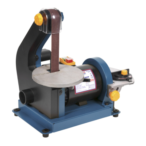
Bench mounting semi-portable belt and disc sander suitable for general woodworking applications. Powerful induction motor with
smooth, bearing-mounted drive pulleys gives quiet operation. Sanding disc table tilts to 45° and is supplied with mitre gauge for
accurate angle sanding. Belt can be used tilted up to 90° from horizontal.
3. SPECIFICATION
Model No:............................................................... SM14.V5
Belt Size(s):.......................................................915 x 100mm
Belt Speed: ............................................................ 460m/min
Disc Size:................................................................ Ø150mm
Disc Speed:..............................................................2950rpm
Dust Extraction Diameter:......................................... Ø35mm
Fuse Rating:.....................................................................10A
Motor Power:.....................................................500W - 230V
Power Supply Cable Length:..........................................1.7m
Table Size: ........................................................225 x 160mm
Table Tilt:........................................................................0-45º
Replacement Sanding Belts: ...........................SB0014:60Grit
.......................................................................SB0015: 80Grit
.....................................................................SB0016: 100Grit
Replacement Sanding Discs:..........................SSD02: 80Grit
4. CONTENTS
5. ASSEMBLY
NOTE: Unpack the sander and check the contents against the parts list. Should there be any
damaged or missing parts, contact your supplier immediately.
5.1. ATTACHING A SANDING DISC
5.2. Attach a sanding disc to the back plate by removing the self adhesive backing and carefully
applying the disc to the plate.
NOTE: The sander may arrive with a disc already applied.
5.3. MOUNTING THE BASE PLATE (FIG.3)
5.3.1. Mount the base plate to the base of the sander using four washers and screws (A) provided.
5.3.2. Tighten all four screws with a hex key to complete base assembly.
5.3.3. Bolt the sander to a stable, fireproof bench or table which is strong enough to take the weight of
the sander and the workpiece.
5.4. INSTALLING THE DISC GUARD/DUST OUTLET (FIG.4)
5.4.1. Position the disc guard against the lower third of the disc, ensuring the two holes are aligned
(fig.4).
5.4.2. Use two screws (A) to tighten the disc guard into place.
5.5. HORIZONTAL & VERTICAL POSITIONS
5.5.1. The belt sander can be used in either a horizontal (fig.1) or vertical (fig.2) position.
5.5.2. To adjust, you must first remove the work support (fig.1).
WARNING! Ensure the fixing screw (fig.1) and worktable screws are tight before using the
sander as it keeps the belt in the vertical position
5.6. MOUNTING THE WORKTABLE - 2 POSITIONS (FIG.1 & 2)
5.6.1. Insert the Table Support Rod into the respective hole.
5.6.2. Position the Worktable no more than 1.6mm from the sanding surface.
5.6.3. Tighten the hex screw with the spanner provided.
5.6.4. Adjust the angle of the worktable using the Angle Gauge Adjustment Knob.
5.7. BELT TENSIONERS (FIG.10 & 11)
5.7.1. Before using the sander, the belt tensioners (fig.10 & 11), need to be turned back approximately
1 turn from their transport position, to allow the electric motor a small amount of movement.
IMPORTANT: If this is not carried out there is a danger that the motor will jam.
Dust Outlet
Tracking Knob
Belt Tension Lever
Fig.2
Sanding Belt
Work Support
On/Off Switch
Support Bolt
Table Support Rod
Mitre Gauge
Sanding Disc
Worktable
Angle Gauge
Fig.1
Fig.3
A
Fig.4
A
Angle Gauge
Adjustment
Knob
Fixing Screw
Table
Support
Rod
Worktable
Angle Gauge
Adjustment
Knob
Mitre Gauge
Base Bar
Bottom Tray
Guard
SM14.V5 Issue 7 (ALL) 23/06/23
Original Language Version
© Jack Sealey Limited
6. OPERATION
WARNING! Before each use rotate the sanding disc by hand to check it is
undamaged and secure. Remove adjusting keys and wrenches before turning the
sander on. Ensure you wear approved safety goggles, gloves, ear defenders and
respiratory protection
WARNING! DO NOT switch the sander on whilst the workpiece is in contact with
the disc or belt.
9Keep all guards and holding screws in place, tight and in good working order. A
guard or other part that is damaged must be repaired or replaced before the sander
is next used, if damaged replace parts.
NOTE: The safety guards are mandatory when the sander is used in premises
covered by the Health & Safety at Work Act.
6.1. ON/OFF SWITCH (FIG.1)
6.1.1. Press the green switch to turn the sander on.
6.1.2. Press the red switch to turn the sander off.
6.2. SANDING TABLE
6.2.1. The table may be tilted through 45° by loosening the screw on the angle gauge (fig.5).
6.2.2. The mitre gauge base bar locates in the groove in the worktable.
6.2.3. When operating the belt sander in the vertical position, mount the worktable at the foot of the belt (fig.2).
7. MAINTENANCE
WARNING! Disconnect sander from the electrical supply before performing any service or maintenance.
9Keep the sander clean and replace a worn or damaged sanding belt or disc.
7.1. ADJUSTING THE SANDING BELT’S TRACKING
7.1.1. If the belt does not run centrally on the drums, the tracking should be adjusted by turning the tracking knob (g.2).
7.1.2. To stabilise the sanding bed, unscrew the support bolt (g.1) until it ‘butts’ up to the underside of the sanding belt bed and lock with nut.
7.2. CHANGING THE SANDING BELT
7.2.1. Remove the work support, guard and bottom tray (g.1) by removing two screws on each side of the sanding belt.
7.2.2. Push the belt tension lever (fig.2) fully to the right to release the tension in the belt.
7.2.3. Remove the old belt. Place the new belt over the two drums (note direction arrows on the inside of the belt).
7.2.4. Move the tension lever back to the left.
7.2.5. Replace guard and bottom tray and then adjust belt tracking if necessary. See 7.1.
7.3. REPLACING SANDING DISC PAD
7.3.1. Remove table and disc guard (fig.1).
7.3.2. Peel the backing off pad and stick the new pad in place.
7.4. PERIODICALLY LUBRICATE THE DRIVE BEARINGS
8DO NOT lubricate motor bearing. The motor is a sealed unit.
7.5. CHANGING DRIVE BELT
7.5.1. Remove the circular sanding disc to gain access to the socket headed screw that secures the aluminium sanding plate (fig.6).
7.5.2. Remove the socket headed screw and washer, followed by the bolt cup to reveal the Woodruff Key (fig.6a).
NOTE: When refitting the disc plate you must align the groove in the disc with the Woodruff Key.
7.5.3. Remove the sanding plate.
7.5.4. Undo the upper and the lower cover screws and remove the disc belt cover (fig.7 & 8).
7.5.5. Remove the old belt.
7.5.6. Fit the new belt over the lower motor spindle pulley and over the top pulley as in fig.9.
7.5.7. To help engage the belt pulley with the top pulley teeth, rotate the motor spindle anti-clockwise while applying horizontal pressure to the
belt at the top pulley (fig.9).
7.5.8. Ensure the belt is correctly located on both pulleys.
Fig.5
Fig.6a
Fig.6 Fig.7 Fig.8
SM14.V5 Issue 7 (ALL) 23/06/23
Original Language Version
© Jack Sealey Limited
7.6. DRIVE BELT TENSION (FIG.9, 10 & 11)
7.6.1. With a firm pressure you should be able to squeeze the belt 5mm on each side as in fig.9.
8DO NOT over tighten as this will damage the motor bearings and belt.
8DO NOT leave the belt slack as it may run off the pulleys during use.
7.6.2. The belt tensioners are shown in fig.10 - two horizontal adjusters and fig.11 - vertical adjuster.
7.6.3. When squeezing the belt; if the motor pulley rises, adjust the vertical adjuster until there is no more vertical play in the motor.
7.6.4. When you are satisfied the belt tension is correct, turn the belt through a couple of revolutions to ensure belt, pulleys etc. all turn freely.
7.6.5. Re-assembly is a reversal of procedures.
Sealey Group, Kempson Way, Suffolk Business Park, Bury St Edmunds, Suffolk. IP32 7AR
01284 757500 sales@sealey.co.uk www.sealey.co.uk
ENVIRONMENT PROTECTION
Recycle unwanted materials instead of disposing of them as waste.All tools, accessories and packaging should be sorted,
taken to a recycling centre and disposed of in a manner which is compatible with the environment. When the product
becomes completely unserviceable and requires disposal, drain any fluids (if applicable) into approved containers and
dispose of the product and fluids according to local regulations.
Note: It is our policy to continually improve products and as such we reserve the right to alter data, specifications and component parts without prior
notice. Please note that other versions of this product are available. If you require documentation for alternative versions, please email or call
our technical team on technical@sealey.co.uk or 01284 757505.
Important: No Liability is accepted for incorrect use of this product.
Warranty: Guarantee is 12 months from purchase date, proof of which is required for any claim.
REGISTER YOUR
PURCHASE HERE
Fig.9 Fig.10 Fig.11
5mm of
movement
when
squeezed
SM14.V5 Issue 7 (ALL) 23/06/23
Original Language Version
© Jack Sealey Limited

Table of contents
Other Sealey Sander manuals

Sealey
Sealey OS600 User manual

Sealey
Sealey SA18/S.V2 User manual

Sealey
Sealey Power Tools SA19/S.V2 User manual

Sealey
Sealey OS600 User manual

Sealey
Sealey SM750.V2 User manual

Sealey
Sealey MS925PS User manual

Sealey
Sealey CP2812V User manual

Sealey
Sealey GSA04 User manual

Sealey
Sealey DAS150T User manual

Sealey
Sealey sa19/S.V2 User manual

Sealey
Sealey SA22.V4 User manual

Sealey
Sealey MA110AS User manual

Sealey
Sealey CP20VRPX User manual

Sealey
Sealey CP20VRP User manual

Sealey
Sealey SM1214 User manual

Sealey
Sealey BB1502 User manual

Sealey
Sealey SA32.V2 User manual

Sealey
Sealey DWS215 User manual

Sealey
Sealey SA22.V3 User manual

Sealey
Sealey SPK600 User manual