4.12.5.4.12.5. TTurn the roller over to use the other groove or use a roller with different sized grooves as required. The groove to be used should beurn the roller over to use the other groove or use a roller with different sized grooves as required. The groove to be used should be
positioned furthest away from you to be in line with the drive path.positioned furthest away from you to be in line with the drive path.
4.12.6.4.12.6. CCheck that the key in the carrier (fig.14.A) is properly seated in its slot. Ensure that the slot on the inside face of the drive roller (fig.14.B)heck that the key in the carrier (fig.14.A) is properly seated in its slot. Ensure that the slot on the inside face of the drive roller (fig.14.B)
is aligned with the key and slide the roller back onto the carrier.is aligned with the key and slide the roller back onto the carrier.
4.12.7.4.12.7. SScrew the black roller retaining knob (fig.14.C) back on to the end of the drive shaft and tighten.crew the black roller retaining knob (fig.14.C) back on to the end of the drive shaft and tighten.
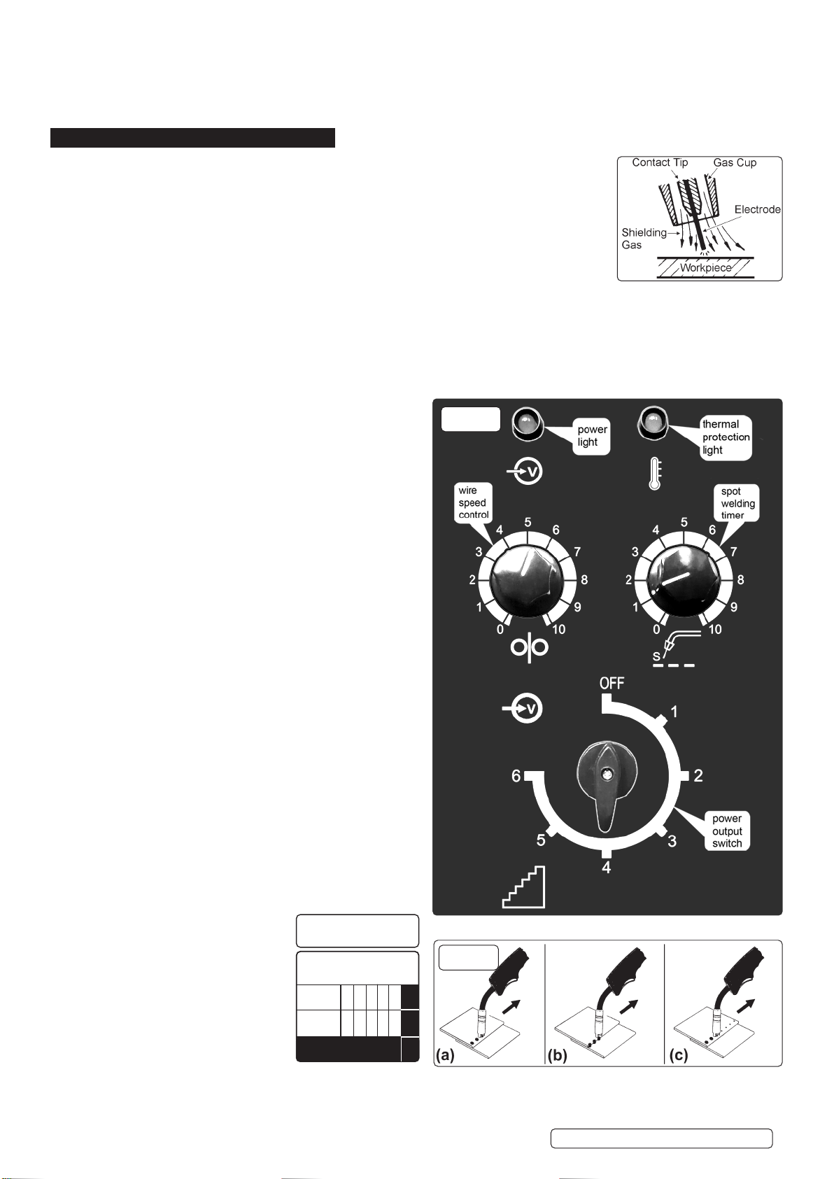
5. MIG/MAG WELDING
A spool of welding wire is positioned on the welder’s spool holder and automatically fed through an insulated
liner in the torch to the tip. The torch assembly consists of a switch, liner, gas hose, and control cable. The switch
activates the wire feed roller and the gas flow. Conversely, releasing the switch stops the wire feed and gas flow.
The weld current is transferred to the electrode (the wire) from the contact tip at the end of the torch. A gas cup fits
over the contact tip to direct the gas flow towards the weld ensuring that the arc welding process is shielded from
oxidising air contaminates. The shielding gas also assists heating of the weld materials. The torch is connected to
the positive side of a DC rectifier, and the negative clamp is attached to the workpiece.
IMPORTANT: Should you have no welding experience, we recommend you seek training from an expert source to
ensure your personal health & safety. Good Mig welding may be achieved only with continued, supervised practice.
5.1. PREPARATION FOR WELDING
IMPORTANT: BEFORE YOU COMMENCE, MAKE SURE THE MACHINE IS SWITCHED OFFAT THE MAINS. IF WELDING A CAR,
DISCONNECT THE BATTERY OR FITAN ELECTRONIC CIRCUIT PROTECTOR. WE STRONGLY RECOMMEND THE USE OF
A Sealey “PROSAF/12V OR 24V IN ORDER TO PROTECT SOPHISTICATED ELECTRONICS. ENSURE YOU HAVE READ &
UNDERSTOOD THE ELECTRICAL SAFETY INSTRUCTIONS IN CHAPTER 1.
NOTE! When welding on a tilted plane ensure the welder is stable and is not in danger of falling over. Ensure the welder is sufficiently secured.
5.2. CONNECTING THE EARTH LEAD.
To ensure a complete circuit, the earth lead must be securely
attached to the work piece that is to be welded.
a) Best connection is obtained by grinding clean the point of
contact on the workpiece before connecting the earth clamp.
b) The weld area must also be free of paint, rust, grease, etc.
c) When welding a vehicle, be sure the vehicle battery is
disconnected or fit an Electronic Circuit Protector available from
your Sealey stockist.
5.2.1. Power Output switch. Set the switch to position 1 or 2 for welding
up to 2mm thickness. Use settings 3,4,5,6. for thicker welds.
5.2.2. Setting the welder controls. In principle, the lower the amperage
required, the slower the wire speed. See setting chart below for
voltage and corresponding wire speeds. Note: these settings are
only a guide and will vary according to the operator’s experience.
5.2.3. Welding mild steel.
To weld mild steel you can use CO² gas for most tasks where
spatter and the high build up of weld do not pose a problem.
Welding with a long arc reduces penetration and widens the arc.
This in turn results in more spatter. A long welding arc can be
appropriate for welding butt joints in thin materials. Welding with a
short arc, at the same weld settings, results in greater penetration
and a narrower weld and reduces the amount of spatter. To
achieve a consistent spatter free and flat weld, you must use an
Argon/CO² mixture.
5.2.4. To weld aluminium use:
✓Argon gas,
✓0.8mm Contact Tip,
✓0.8mm Aluminium Wire,
5.3. OVERLOAD PROTECTION.
5.3.1. Thermostatic overload protection is provided. When an overload
has occurred, leave the unit to cool. The thermostat will
automatically reset the unit when the temperature has returned
within limits
5.3.2. Spot Welding. Spot welding may be carried out as shown in fig.16.
It will be necessary to fit a spot welding gas cup.
(a) Overlapping metal sheets with a maximum thickness of
0.8 mm may be welded as indicated.
(b) Alternatively they may be welded
edge to surface as indicated.
(c) For thicker sheet pre drilled holes
may be employed.
5.3.3. Use the wire feed control
in conjunction with the spot
weld timer beside it. To activate
the timer turn the knob clockwise.
The settings indicated in the black
portion of the chart are for guidance
only and may vary with operators
experience.
g.15
Spot Welding Timer 6
Wire 0.6mm Steel
Argon / CO² Mix
Voltage
Step: 1 2 3 4 5 6
Wire
Speed: 5 6 7 8 9 10
SETTINGS SHOWN
AS GUIDE ONLY
g.16
Original Language Version
© Jack Sealey Limited SUPERMIG200.V2 Issue 1 11/07/22