manuals.online logo
Brands
  1. Home
  2. •
  3. Brands
  4. •
  5. Sealey
  6. •
  7. Welding System
  8. •
  9. Sealey SR2000 User manual

Sealey SR2000 User manual

INSTRUCTIONS FOR
STUD WELDING KIT 230V
MODEL NO: SR2000
Thank you for purchasing a Sealey product. Manufactured to a high standard, this product will, if used according to these instructions,
and properly maintained, give you years of trouble free performance.
IMPORTANT: PLEASE READ THESE INSTRUCTIONS CAREFULLY. NOTE THE SAFE OPERATIONAL REQUIREMENTS, WARNINGS & CAUTIONS. USE
THE PRODUCT CORRECTLY AND WITH CARE FOR THE PURPOSE FOR WHICH IT IS INTENDED. FAILURE TO DO SO MAY CAUSE DAMAGE AND/OR
PERSONAL INJURY AND WILL INVALIDATE THE WARRANTY. KEEP THESE INSTRUCTIONS SAFE FOR FUTURE USE.
1. SAFETY
1.1. Electrical Safety
WARNING! It is the user’s responsibility to check the following:
Check all electrical equipment and appliances to ensure that they are safe before using. Inspect power supply
leads, plugs and all electrical connections for wear and damage. Sealey recommend that an RCD
(Residual Current Device) is used with all electrical products. You may obtain an RCD by contacting your
local Sealey dealer.If the kit is used in the course of business duties, it must be maintained in a safe
condition and routinely PAT (Portable Appliance Test) tested.
9Electrical safety information, it is important that the following information is read and understood.
9Ensure that the insulation on all cables and on the appliance is safe before connecting it to the power supply.
9Regularly inspect power supply cables and plugs for wear or damage and check all connections to ensure that they are secure.
9Ensure that the voltage rating on the appliance suits the power supply to be used and that the plug is tted with the
correct fuse - see fuse rating in these instructions.
8DO NOT pull or carry the appliance by the power cable.
8DO NOT pull the plug from the socket by the cable.
8DO NOT use worn or damaged cables, plugs or connectors.
9 This product is tted with a BS1363/A 13 Amp 3 pin plug.
If the cable or plug is damaged during use, switch o󰀨 the electricity supply and remove from use.
9 Replace a damaged plug with a BS1363/A 13 Amp 3 pin plug. If in doubt contact a qualied electrician.
a) Connect the GREEN/YELLOW earth wire to the earth terminal ‘E’.
b) Connect the BROWN live wire to the live terminal ‘L’.
c) Connect the BLUE neutral wire to the neutral terminal ‘N’.
Ensure that the cable outer sheath extends inside the cable restraint and that the restraint is tight.
9 Sealey recommend that repairs are carried out by a qualied electrician.
9Only use one single extension cable at a one time. DO NOT daisy chain extension cables. Unwind the
extension cable fully.
1.2. General
8DO NOT touch heating parts with bare hands.
8DO NOT touch live electrical parts or electrodes with bare skin or wet clothing.
8DO NOT operate in the vicinity of containers under pressure, or in the presence of explosive dust, gases or fumes.
8DO NOT cover or stick objects into any of the ventilation holes on the equipment.
WARNING! The magnetic elds created by high currents may a󰀨ect the operation of pacemakers. Wearers
of vital electronic equipment or those who have metallic surgical implant should consult their Doctor before using equipment.
8DO NOT wear clothing with metallic components e.g. belt buckles, buttons, zips when working with the equipment as it can
cause such items to heat up.
9Remove any metallic components e.g. keys, chains, tools etc. while you operate the equipment and DO NOT wear any metallic
objects such as jewellery, watches, piercings etc. on your body.
8DO NOT use the equipment in the rain or in humid conditions or immerse it in water.
8DO NOT leave the equipment unattended whilst turned on.
8DO NOT attempt to repair or service the equipment.
9Ensure area is adequately ventilated and dry.
9Ensure ambient temperature is between -10 to 40 °C
9Avoid using in bright sunshine or rain.
8DO NOT use the equipment in an environment where the air is polluted with conductive dust or gases.
WARNING! Fumes and smoke from hot/burning paints, adhesives etc. are toxic. Wear a suitable mask in such circumstances.
2. INTRODUCTION
Supply: 230V-13A (13A Plug tted). Professional quality stud welder for fast, e󰀩cient body repairs. Removes dents quickly, without
holes or the need to remove interior trim. No burn through means that removal of studs and washers is easy and preparation work
before repainting is minimised. Suitable for use on steel or aluminium and can weld studs, washers and tabs. Patented quick puller
attachment allows removal of smaller dents without the need for studs or washers. Supplied in heavy-duty storage case.
Indoor use only
Recommended fuse rating
13 Amp
SR2000 Issue 1 15/06/18
Original Language Version
© Jack Sealey Limited
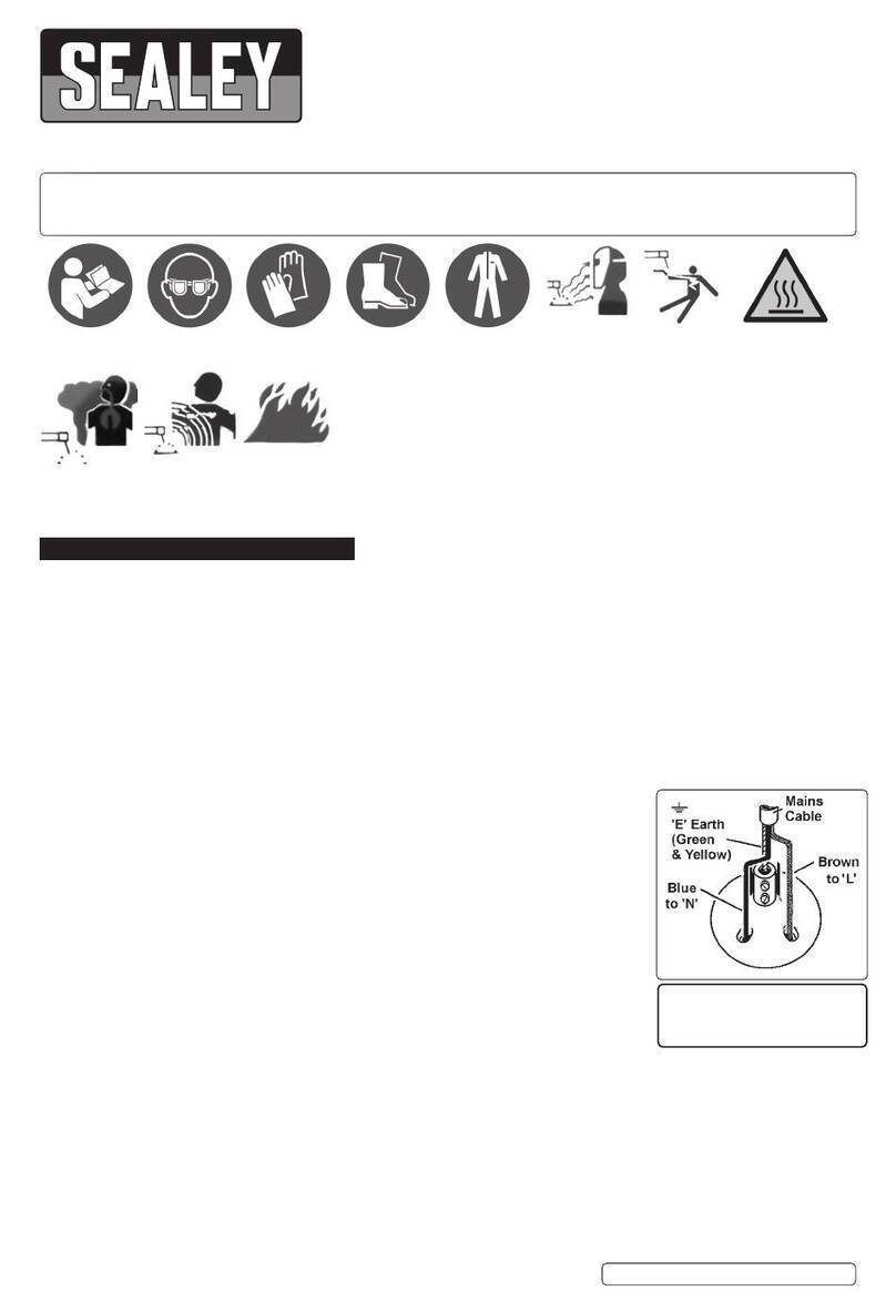
Refer to
instruction
manual
Wear protective
gloves
Wear eye
protection
Wear face
mask
Wear ear
protection
Wear protective
clothing
Do not use in
the vicinity of a
pacemaker
Wear welding
mask
3. SPECIFICATION
Model no:................................................................. SR2000
Input power .......................................................... 230V 50Hz
Input current.......................................................................3A
Output max. current ..................................................... 5000A
Duty cycle: ................................... 100% @8~15 Al studs/min
Consumables:
Al-Mg Studs pack of 10.......................................SR2000.AM
Al-Mg-Si Studs pack of 10.................................SR2000.AMS
Electrode kit ...........................................................SR2000.E
Pull washer pack of 10........................................SR2000.PW
Start washer pack of 10 ......................................SR2000.SW
Tabs pack of 10...................................................... SR2000.T
Triangle washers.................................................SR2000.TW
4. OPERATION
4.1. General guidelines
4.1.1. When welder is not in use switch o󰀨 and disconnect from power supply.
4.1.2. Welder must be switched o󰀨 and disconnected from power supply for a minimum of 5 minutes before any maintenance is carried out
to ensure complete discharge of capacitors.
4.1.3. Good contact between studs, tabs and the collet is required to ensure good welds. A loose t will result in melting of the stud surface.
4.1.4. Welding might cause welding arc and slight metal spatter so protective safety garments and eye protection are required at all times.
4.1.5. Ensure there are no ammable materials or liquids in the work area.
4.1.6. DO NOT modify the cable or any part of the welding unit in any way.
4.2. Usage guidelines.
4.2.1. Ensure surfaces to be worked on are bare of all coatings, corrosion and grease.
4.2.2. All welding components (studs, tabs, ground pins etc.) must be clean and corrosion free.
4.2.3. Ensure that adequate downward pressure is applied to the stud gun in use as good contact for both ground pins and welding
attachments is essential to the welding process. Downward pressure adjustment is provided by altering the pre-load on the
collet spring by rotating the thumb wheel in the barrel (g.1).
4.2.4. Voltage adjustment is provided by the rotating knob near the trigger. Voltage setting indication is provided by the LED display in the
stock handle of the welder.
4.3. Power Settngs.
4.3.1. For aluminium stud welding an initial voltage of 28 is recommended, adjusting up or down as required depending on weld results. DO
NOT make an adjustment of more than 3 volts at a time before re-testing.
4.3.2. For steel tab welding an initial voltage of 22 is recommended, adjusting up or down dependant on results. DO NOT make an
adjustment of more than 3 volts at a time before re-testing.
WARNING!: DO NOT alter voltage settings rapidly in a short period of time as power must be allowed to dissipate from the welder.
Frequent power changes in a short period of time will damage the unit.
4.4.  Studweldingg.2,g.3.
4.4.1. Disconnect equipment from power supply.
4.4.2. In normal use the collet will wear and loosen its grip on the welding studs. This can be corrected by gently squeezing the jaws of the
collet together using a pair of pliers or an alternative form of controlled pressure. DO NOT hit with a hammer.
4.4.3. Stud heads must protrude 2mm beyond the end of the collet (g.3). Turn adjustable stop in and out to set stud height. The stud must
t up against stop. Tighten lock nut to x position.
4.4.4. Install the two ground pins on opposite corners of the mounting plate (g.2).
4.4.5. Insert the collet into the collet holder. The at surface of the tip of the stud should extend 2-4mm past the tips of the ground pins(g.2).
4.4.6. Set power level as guided in section 4.3.
Original Language Version
© Jack Sealey Limited
fig.3
fig.2
fig.1
SR2000 Issue 1 15/06/18
4.5.  Tabweldingg.4.
4.5.1. Disconnect equipment from power supply.
4.5.2. Insert tab welding tip into collet of machine and secure with collet lock nut.
4.5.3. Insert tab into tab welding tip. Push t is required.
4.5.4. Adjust the ground pin such that the tip of the tab protrudes 4mm past the end of the ground pin (g.4).
4.5.5. Set power level as guided in section 4.3.
4.6.  Dentstickpullingadaptor.g.5
4.7. Insert adaptor into welder collet and tighten collet nut to hold it.
4.7.1. Insert ground pin into base plate using screw knob to clamp it. The ground pin head should be 2 to 4mm behind the tip of
the adaptor.
4.7.2. Set power level as guided in section 4.3.
NOTE: The Dent Stick Adapter is designed to be used on small dents or nishing work only. It is not designed for large
damage repair. Over welding and over pulling could result in damage to the welding tip, the panel or the welder.
4.8. Recommended voltage setting.
Original Language Version
© Jack Sealey Limited
fig.4
fig.5
Function Recommended voltage (V)
Al. stud Ø4.0 30 - 32
22 - 20
22 - 20
18 - 20
18 - 20
Dent
Stick
SR2000 Issue 1 15/06/18
5. TROUBLESHOOTING
Sealey Group, Kempson Way, Suffolk Business Park, Bury St Edmunds, Suffolk. IP32 7AR
01284 757500 01284 703534 sales@sealey.co.uk www.sealey.co.uk
ENVIRONMENT PROTECTION
Recycle unwanted materials instead of disposing of them as waste. All tools, accessories and packaging should be sorted, taken to
a recycling centre and disposed of in a manner which is compatible with the environment. When the product becomes completely
unserviceable and requires disposal, drain any fluids (if applicable) into approved containers and dispose of the product and fluids
according to local regulations.
Note: It is our policy to continually improve products and as such we reserve the right to alter data, specifications and component parts without prior
notice.
Important: No Liability is accepted for incorrect use of this product.
Warranty: Guarantee is 12 months from purchase date, proof of which is required for any claim.
Original Language Version
© Jack Sealey Limited SR2000 Issue 1 15/06/18
P1, P2, P3 indicator lights on the power supply
are not lit.
1) Check the power supply.
2) Check the input cable.
3) Check the main switch.
4) There is a failure. Please contact the manufacturer.
Voltage meter display “.000”, when the welder is
turned on.
1) Adjust the voltage control knob on the Welder.
2) Restart the Welder.
3) Trigger on and o󰀨 several times.
4) There is a failure. Please contact to the manufacturer.
P1 indicator light is not lit. 1) Check the power supply,
2) Check the input cable.
3) Check the main switch.
4) Over heat protection, wait for welder to cool and restart.
Sparks. While steel tab welding 1) Check the ground pin for good connection.
2) Check the work panel for oxidation or dirt.
3) Lower power setting.
4) Increase pressure on ground pins & tabs when welding.
The stud did not weld properly. It can be easily
pulled o󰀨 of the panel.
1) Check Stud height adjustment. Stud head should be 2-4 mm past
the head of the ground pin.
2) Check the ground pin is making good connection.
3) Check the work panel for oxidation or dirt.
4) Increase output voltage.
The stud burns through the panel. 1) Reduce output voltage.
2) Check the work panel for oxidation or contamination.
3) Adjust the gun, reduce pressure.
No output when the trigger is pulled. 1) Check P1, P2, P3 indicator lights. All lights should be on.
2) Check the o󰀨/on switch.
3) Check the power supply to the welder.
4) Check the welding stud/tab and the ground pin have good
connection to the panel.
5) There is a failure. Please contact Sealey stockist.

Other Sealey Welding System manuals

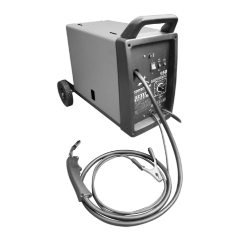
Sealey SUPERMIG140 User manual

Sealey

Sealey SUPERMIG140 User manual

Sealey TIG150T User manual

Sealey

Sealey TIG150T User manual

Sealey MW181 User manual

Sealey

Sealey MW181 User manual

Sealey PL60/1.V2 User manual

Sealey

Sealey PL60/1.V2 User manual

Sealey MW145.V2 User manual

Sealey

Sealey MW145.V2 User manual

Sealey 180XT User manual

Sealey

Sealey 180XT User manual

Sealey MIGHTYMIG90.V2 User manual

Sealey

Sealey MIGHTYMIG90.V2 User manual

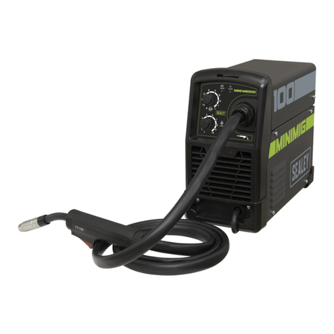
Sealey MINIMIG100 User manual

Sealey

Sealey MINIMIG100 User manual

Sealey MIG/T15 User manual

Sealey

Sealey MIG/T15 User manual

Sealey IMIG160.V2 User manual

Sealey

Sealey IMIG160.V2 User manual

Sealey SUPERMIG250 User manual

Sealey

Sealey SUPERMIG250 User manual

Sealey MIGHTYMIG150.V2 User manual

Sealey

Sealey MIGHTYMIG150.V2 User manual

Sealey SUPERMIG180.V3 User manual

Sealey

Sealey SUPERMIG180.V3 User manual

Sealey 150XL.V3 User manual

Sealey

Sealey 150XL.V3 User manual

Sealey POWER WELDERS 140XL/AK1 User manual

Sealey

Sealey POWER WELDERS 140XL/AK1 User manual

Sealey MIGHTYMIG170.V3 User manual

Sealey

Sealey MIGHTYMIG170.V3 User manual

Sealey SuperMig185 User manual

Sealey

Sealey SuperMig185 User manual

Sealey MIG/SGT15.V2 User manual

Sealey

Sealey MIG/SGT15.V2 User manual

Sealey Supermig185.V2 Firmware update

Sealey

Sealey Supermig185.V2 Firmware update

Sealey SUPERMIG 150/5.V2 User manual

Sealey

Sealey SUPERMIG 150/5.V2 User manual

Sealey 140XT.V2 User manual

Sealey

Sealey 140XT.V2 User manual

Sealey SUPERMIG255.V2 User manual

Sealey

Sealey SUPERMIG255.V2 User manual

Sealey PP30 User manual

Sealey

Sealey PP30 User manual

Sealey POWERMIG2500 User manual

Sealey

Sealey POWERMIG2500 User manual

Popular Welding System manuals by other brands

Miller RCCS-5 owner's manual

Miller

Miller RCCS-5 owner's manual

Suministros Orozco Spotter 5500 instruction manual

Suministros Orozco

Suministros Orozco Spotter 5500 instruction manual

Nupi Elofit 00E8500 User handbook

Nupi

Nupi Elofit 00E8500 User handbook

NewArc R4000 Operational manual

NewArc

NewArc R4000 Operational manual

Migatronic MWF 50 2 YARD instruction manual

Migatronic

Migatronic MWF 50 2 YARD instruction manual

Linde BOC RAPTOR 250R MIG operating manual

Linde

Linde BOC RAPTOR 250R MIG operating manual

Abicor Binzel ROBO WH 654 Package Guide

Abicor Binzel

Abicor Binzel ROBO WH 654 Package Guide

Sua ionMig 200 PFC Operation manual

Sua

Sua ionMig 200 PFC Operation manual

Bernard Q-Gun Q150-1.4 Specification sheet

Bernard

Bernard Q-Gun Q150-1.4 Specification sheet

PowCon SGS 30A owner's manual

PowCon

PowCon SGS 30A owner's manual

Miller Dimension NT 450 owner's manual

Miller

Miller Dimension NT 450 owner's manual

Snap-On TIG 130i manual

Snap-On

Snap-On TIG 130i manual

ESAB Aristo WeldCloud Mig U5000i instruction manual

ESAB

ESAB Aristo WeldCloud Mig U5000i instruction manual

Thermal Arc 186 AC Setup guide

Thermal Arc

Thermal Arc 186 AC Setup guide

Everlast POWER MTS 200 Operator's manual

Everlast

Everlast POWER MTS 200 Operator's manual

Rival TIG 185 DC operating manual

Rival

Rival TIG 185 DC operating manual

Lincoln Electric POWER WAVE S500 Operator's manual

Lincoln Electric

Lincoln Electric POWER WAVE S500 Operator's manual

Acklands Limited AK-MATIC 1250X owner's manual

Acklands Limited

Acklands Limited AK-MATIC 1250X owner's manual

manuals.online logo
manuals.online logoBrands
  • About & Mission
  • Contact us
  • Privacy Policy
  • Terms and Conditions

Copyright 2025 Manuals.Online. All Rights Reserved.