4.1. LEAD CONNECTION
MMAMode:ConnecttheelectrodeholdertothePositive(+)connector(fig.1.4)andtheearthleadtotheNegative(-)connector(fig.1.3).
TIGMode:ConnecttheearthclamptothePositive(+)connectorandtheTIGtorchtothenegative(-)connector.
4.2. GAS CONNECTION
4.2.1. Using the clear tubing supplied connect the regulator to the gas inlet on the back of the inverter and gas outlet on the front (fig.1.1).
Secure the tubing on each connector by using the worm drive clamps supplied.
4.2.2. Open the regulator before opening the cylinder valve. Test for leaks.
4.2.3. Set the gas flow to suit the welding parameters required.
4.2.4. If necessary the gas flow can be adjusted during welding using the regulator knob.
4.3. If using the optional torch kit, connect the control lead of the torch assembly to the torch control connection (fig.1.2).
4.4. MMA: DC STICK ARC WELDING
4.4.1. UsingtheUpandDownkeys,settheweldingmodeselector(g.2.1) to , the welding current may be adjusted by means of the
adjustmentknob(g.2.5).
4.4.2. Thehotstartcurrent(g.3.B)andarcforcecurrentonly(g.3.K)canbeadjustedinthismodetomatchthematerialbeingwelded.
4.4.3. To select the parameter push the parameter setting control to cycle between functions. The value may be adjusted by using the
adjustmentknob(g.2.1).Thevaluesaredisplayedonthedigitaldisplay.(g.2.4)
4.5. DC TIG WELDING
4.5.1. UsingtheUpandDownkeys,settheweldingmodeselector(g.2.1)to for high frequency start or for lift start.
4.5.2. Thepre-owtime(g.2.A),weldingcurrent(g.2.D)andgasdelaytimeindicator(g.2.J)maybeadjustedinthismode.
4.5.3. To select the parameter press the parameter setting control to cycle between functions. The value may be adjusted rotating the
settingcontrol(g.2.5).
4.5.4. 2or4touchtriggercontrolmaybeselectedbyusingthetriggermodeselector(g.2.3).
4.5.5. 2 touch allows the power to be applied whilst the trigger is pressed.
4.5.6. 4 touch latches the trigger until the pressed for a second time.
4.5.7. The 4 touch mode is useful for long runs of weld, saving operator fatigue and allowing a steadier weld. In this mode the power will be
applied until the selected down slope time has elapsed.
4.6. DC PULSE TIG WELDING
4.6.1. UsingtheUpandDownkeys,settheweldingmodeselector(g.2.91to for high frequency start or for lift start.
4.6.2. Selectthepulsefunctionatg.2.2.
4.6.3. Thepre-owtime(g.2.A),pulsepeakcurrent(g.2.D),pulsewidth(g.2.F),pulsefrequency(g.2.G),pulsebackgroundcurrent
(g.2.G)andgasdelaytime(g.2.J)mayallbeadjustedinthismode.
4.6.4. To select the parameter press the parameter setting control to cycle between functions. The value may be adjusted by rotating the
settingcontrol(g.2.5).
4.7. STATUS WARNING LIGHTS
4.7.1. PowerIndicator(g.2.6).Indicatorilluminatedwhenswitchedon.
4.7.2. OverheatIndicator(g.1.7).Illuminatedwhenmachineisoverheated.Inthisconditionthemachinewillshutdownuntilthetemperature
falls to acceptable limits.
4.7.3. Over/under voltage. Indicates that the supply voltage is outside the required parameters.
5. MAINTENANCE
▲DANGER Unplug the inverter from the mains power supply before connecting or disconnecting cables, performing maintenance or
service. Direct contact with the inverter circuit is dangerous.
5.1. To avoid a build up of dust inside the machine which may block or restrict the ventilation system, periodically remove the covers and
remove the dust with a low pressure air jet or vacuum cleaner. Replace covers immediately. Under no circumstances should the
machine be operated with the covers removed.
5.2. TORCH. Avoid resting the the torch and its associated cable on any hot surfaces. If the insulation is damaged in any way the torch
must not be used.
5.3. Periodicallychecktheconditionofthegastubingandtheconnections.
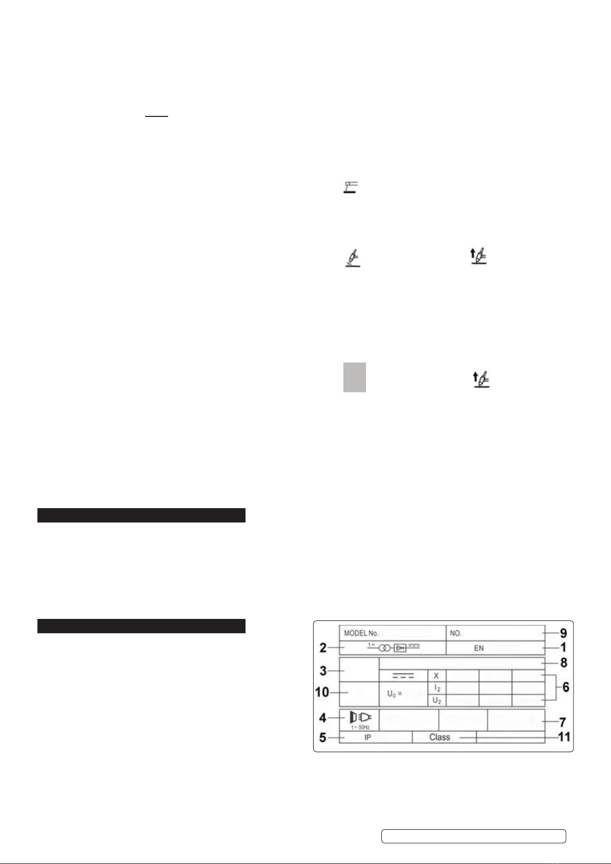
6. RATINGS PLATE SYMBOLS
On the rear of the inverter is the ratings plate, giving the following
Data:
1 - The BS/EU standard relating to the safety and construction of
Arc welding and associated equipment.
2 - Inverter-transformer-rectifier symbols.
3 - Symbol indicating welding processes available. .
4 - Symbol for Single-phase AC supply.
5 - Rating of internal protection provided by casing.
6 - Output
U0: Maximum open-circuit voltage.
I2, U2: Current and corresponding voltage.
X: Welding ratio based on a 10 minute cycle.
20% indicates 2 minutes welding and 8 minutes rest,
100% would indicate continuous welding.
7 - Mains Supply U1: Rated supply voltage and frequency.
I1max: Maximum current. I1eff: Maximum effective current.
8 - A/V - A/V: Welding current adjustment range and corresponding voltages.
Original Language Version
© Jack Sealey Limited TIG180S.V3, TIG200S.V3 Issue 2 (1) 31/01/23