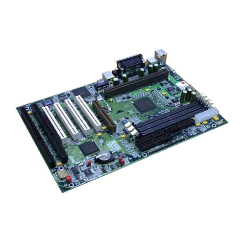
Seanix Gatineau User manual

Version 1.0
Gatineau
Motherboard
Reference Manual

2
USER’S NOTICE
No part of this product, including the product and software, may be reproduced,
transmitted, transcribed, stored in a retrieval system or translated into any language in
any form by any means without the express written permission of Seanix Technology
(Canada) Inc. (herein after referred to as Seanix) except documentation kept by the
purchaser for backup purposes.
Seanix provides this manual "as is" without warranty of any kind, either express or
implied, including but not limited to the implied warranties or conditions of
merchantability or fitness for a particular purpose. In no event shall Seanix be liable for
any loss or profits, loss of business, loss of use or data, interruption of business, or for
indirect, special, incidental, or consequential damages of any kind? even if Seanix has
been advised of the possibility of such damages arising from any defect or error in this
manual or product. Seanix may revise this manual from time to time without notice.
Products mentioned in this manual are mentioned for identification purposes only.
Product names appearing in this manual may or may not be registered trademarks or
copyrights of their respective companies.
The product name and revision number are both printed on the board itself. Manual
revisions are released for each design represented by the digit before and after the
period and for manual updates represented by the third digit in the manual revision
number. For updated BIOS, drivers, or product release information you may visit
Seanix’ home page at: http://www.seanix.com
Copyright ©1999 Seanix Technology (Canada) Inc. All rights reserved.
Trademarks
Seanix makes no warranty of any kind with regard to this material, including, but not
limited to, the implied warranties of merchantability and fitness for a particular purpose.
Seanix assumes no responsibility for any errors that may appear in this document.
Seanix makes no commitment to update nor to keep current the information contained
in this document. No part of this document may be copied or reproduced in any form or
by any means without prior written consent of Seanix.
Pentiumand Celeronare registered trademarks of the Intel Corporation.
Microsoftis a registered trademark of the Microsoft Corporation.
Windowsis a registered trademark of the Microsoft Corporation.
Third-party brands and trademarks are the property of their respective owners.
Copyright 1999, Seanix.

3
Contents
1.Product Description...................................................................................................5
Features of the Gatineau Motherboard........................................................................5
Motherboard Layout.....................................................................................................7
Central Processing Unit...............................................................................................8
Memory........................................................................................................................8
Chipset.......................................................................................................................10
Super I/O Controller...................................................................................................13
BIOS System Support................................................................................................15
Expansion Slots.........................................................................................................17
Hardware Monitor ......................................................................................................17
Onboard LAN (Optional)............................................................................................18
Onboard Sound (Optional).........................................................................................18
Wake On LAN Header (WOL)....................................................................................19
Front Panel Connector...............................................................................................19
CD Audio in Connector..............................................................................................19
Fan Connectors .........................................................................................................20
Main Power Connector ..............................................................................................20
Management Extension Hardware.............................................................................20
LS-120 Support..........................................................................................................21
System Security.........................................................................................................21

4
2.Installation and Settings..........................................................................................22
Jumper Settings.........................................................................................................22
CPU Installation.........................................................................................................25
System Memory Installation.......................................................................................27
Battery Replacement .................................................................................................28
Expansion Card Installation.......................................................................................28
3.Using the BIOS Setup Program...............................................................................30
Standard CMOS Setup..............................................................................................32
BIOS Features Setup.................................................................................................34
Chipset Features Setup.............................................................................................37
Power Management Setup ........................................................................................40
PNP/PCI Configuration..............................................................................................43
Integrated Peripherals................................................................................................44
Load BIOS Defaults...................................................................................................46
Load Setup Defaults..................................................................................................46
Auto-Detect Hard Disks .............................................................................................46
Supervisor Password and User Password settings ...................................................46
IDE HDD Auto Detection............................................................................................46
Save and Exit Setup ..................................................................................................46
Exit Without Saving....................................................................................................46
Upgrading the BIOS...................................................................................................47
4.Error and Information Messages ............................................................................48
5.Glossary....................................................................................................................51
6. Specifications..........................................................................................................54

5
1.Product Description
Pentium®Processor-based ATX motherboard
The Gatineau Motherboard is an innovative, high performance ATX platform for the
Celeron, Pentium®II and PentiumIII processors - giving you the performance needed
for today’s Windows based business applications and providing performance for
tomorrow’s even more advanced software.
The Accelerated Graphics Port (AGP) is a graphics controller bus, freeing system
resources to quickly move memory-intensive graphics data in and out of system
memory. This enables a new level of sophisticated lifelike 3-D graphics with higher
speeds and resolutions than previously possible. Off-loading bandwidth-intensive
graphics from the PCI bus also contributes to an increase in overall system
performance.
Features of the Gatineau Motherboard
•ATX form factor of 300mm x 207mm.
Microprocessor:
•Single IntelCeleron, PentiumII or PentiumIII processor
•100MHz and 66MHz host bus speeds
•All current processor speeds, voltages, and bus frequencies
•Slot 1 connector
Main memory:
•Three 168-pin DIMM sockets
•Supports up to 768 MB of synchronous DRAM (SDRAM) memory
•Error checking and correcting (ECC)
•Intel 82443BX peripheral controller (PAC)
•Integrated PCI bus mastering controller
•Integrated Accelerated Graphics Port (A.G.P.) controller
•Intel 82371EB PCI ISA IDE Xcelerator (PIIX4E)
•Supports up to four IDE drives or devices
•Multifunction PCI-to-ISA bridge
•Universal Serial Bus (USB) and DMA controllers
•Two fast IDE interfaces
•Power management logic

6
•Real-time clock
I/O features:
•National Semiconductor PC87351
•Integrates standard I/O functions
•Two USB ports
•Seven expansion slots:
One AGP slot
Three PCI slots
One shared PCI/ISA slot
One ISA slot
Other features:
•AWARD BIOS
•Plug and Play compatible
•Advanced Power Management (APM) 1.2
•Advanced Configuration and Power Interface (ACPI) 1.0

7
Motherboard Layout
✏NOTE
This motherboard outlines with full-feature on-board sound & on-board Lan.
Components shown do not come on all Gatineau motherboard.
AGP
PCI
ISA
J29
J30 J31
1 2
WOL
JP8
JP2
JP1
JP9
JP10
Intel
AGPset
Intel
PCIset
ES1373
1
27
Reset
HDD LED
Speaker
Power LED
InfraRed
Sleep
Power on
WOR
Slot 1
connector
ATX
Power
connector
DIMM
sockets
Front panel connectors
Primary IDE
Secondary IDE
Floppy
Mouse
PS/2 port
Keyboard
PS/2 port
USB
ports
Line-In
Mic
Line-Out
Parallel port
(printer port LPT1)
Serial port
(COM1)
Serial port
(COM2)
LAN
connector
Joystick / MIDI
connector
CPU jumpers
Battery
Chassis Intrusion
Fan1 Fan2

8
Central Processing Unit
This motherboard is designed to operate with a single IntelCeleron, Pentium®II, or
Pentium®III processor. The processor’s VID pins automatically program the voltage
regulator on the motherboard to the required processor voltage. In addition, the front
side bus speed (100 MHz and 66 MHz) is automatically selected.
The Intel processors include the following features:
•Intel's highest performance processor, combining the power of the IntelPentium®III
processor with the capabilities of MMX™ technology and new Katmai instructions.
•Takes advantage of the same high-performance Dual Independent Bus architecture
used in the IntelPentiumIII processor for high bandwidth and performance.
•Single Edge Contact (S.E.C.) cartridge packaging technology delivers high
performance processing and bus technology to mainstream systems. The cartridge
includes the processor core, second-level cache, thermal plate, and back cover.
•Optimized for 32-bit applications running on advanced operating systems.
•Data integrity and reliability features include system bus ECC, Fault Analysis,
Recovery, and Functional Redundancy Checking.
Memory
The motherboard has three dual inline memory module (DIMM) sockets. Synchronous
DRAM (SDRAM) can be installed in any of the 3 sockets. EDO DIMMs are not
supported. Minimum memory size is 16 MB; maximum memory size is 768 MB. Memory
size can vary between sockets.
The motherboard supports the following memory features:
•168-pin DIMMs
•100 or 66 MHz SDRAM
•Non-ECC (64-bit) and ECC (72-bit) memory
•3.3 V memory only
•Single- or double-sided DIMMs in the following sizes:
DIMM Size Non-ECC Configuration ECC Configuration
16 MB 2 Mbit x 64 2 Mbit x 72
32 MB 4 Mbit x 64 4 Mbit x 72
64 MB 8 Mbit x 64 8 Mbit x 72
128 MB 16 Mbit x 64 16 Mbit x 72
256 MB 32 Mbit x 64 32 Mbit x 72

9
✏NOTE
Processors with 100 MHz front-side bus should be paired only with 100 MHz SDRAM.
Processors with 66 MHz front side bus can be paired with either 66 MHz or 100 MHz
SDRAM.
SDRAM
Synchronous DRAM (SDRAM) improves memory performance through memory access
that is synchronous with the memory clock. This simplifies the timing design and
increases memory speed because all timings are dependent on the number of memory
clock cycles.
✏NOTE
All memory components and DIMMs used with this motherboard must comply with the
PC SDRAM specifications. These include the PC SDRAM Specification (memory
component specific), the PC Un-buffered DIMM Specification, and the PC Serial
Presence Detect Specification. You can access these documents through the Internet
at http://www.intel.com/design/pcisets/memory/
ECC Memory
ECC memory detects multiple-bit errors and corrects single-bit errors. When ECC
memory is installed, the BIOS supports both ECC and non-ECC mode. ECC mode is
enabled in the Setup program. The BIOS automatically detects if ECC memory is
installed and provides the Setup option for selecting ECC mode. If any non-ECC
memory is installed, the Setup option for ECC configuration does not appear and ECC
operation is not available.
The following table describes the effect of using Setup to put each memory type in each
supported mode. Whenever ECC mode is selected in Setup, some performance loss
occurs.
Cache Memory
The Intel microprocessors include 32 KB (16K/16K) non-blocking level one cache and
up to 1 MB unified, non-blocking level two cache on the substrate in the Single Edge
Connector (S.E.C.) cartridge. The size of level two cache varies between the Intel
Celeron, PentiumII and PentiumIII processors, it could be 0KB, 128KB, 256KB or
512 KB.

10
Chipset
The Intel 440BX PCIset includes a Host-PCI bridge integrated with both an optimized
DRAM controller and an Accelerated Graphics Port (A.G.P.) interface. The I/O
subsystem of the 440BX is based on the PIIX4E, which is a highly integrated PCI-
ISA/IDE Accelerator Bridge. This chipset consists of the Intel 82443BX PCI/A.G.P.
controller (PAC) and the Intel 82371EB PCI/ISA IDE Xcelerator (PIIX4E) bridge chip.
Intel 82443BX PCI/A.G.P. controller (PAC)
The PAC provides bus-control signals, address paths, and data paths for transfers
between the processor’s host bus, PCI bus, Accelerated Graphics Port (A.G.P.), and
main memory. The PAC comes in a 492-pin BGA package and features:
•Processor interface control
Support for processor host bus frequencies of 100 MHz or 66 MHz
32-bit addressing
Desktop Optimized GTL+ compliant host bus interface
•Integrated DRAM controller, with support for:
+3.3 V only DIMM DRAM configurations
Up to four double sided DIMMs
Synchronous 100-MHz or 66-MHz SDRAM
SDRAM 64-bit data interface with ECC support
•A.G.P. interface
Complies with the A.G.P. specification (see Section 6.2 for specification
information)
Support for +3.3 V PCI-66, A.G.P.-66/133 devices
Synchronous coupling to the host-bus frequency
•PCI bus interface
Complies with the PCI specification Rev 2.1, +5 V 33 MHz interface
Asynchronous coupling to the host-bus frequency
PCI parity generation support
Data streaming support from PCI-to-DRAM
Support for concurrent host, A.G.P., and PCI transactions to main memory
•Data buffering
DRAM write buffer with read-around-write capability
Dedicated host-to-DRAM, PCI0-to-DRAM, and PCI1/A.G.P.-to-DRAM read buffers
A.G.P. dedicated inbound/outbound FIFOs (133/66 MHz), used for temporary data
storage

11
•Power management functions
Support for system suspend/resume (DRAM and power-on suspend)
Compliant with ACPI power management
•SMBus support for desktop management functions
•Support for system management mode (SMM)
Intel 82371EB PCI ISA IDE Xcelerator (PIIX4E)
The PIIX4 is a multifunction PCI device implementing the PCI-to-ISA bridge, PCI IDE
functionality, Universal Serial Bus (USB) host/hub function, and enhanced power
management. The PIIX4E comes in a 324-pin package that features:
•Multifunction PCI-to-ISA bridge
Support for the PCI bus at 33 MHz
Complies with the PCI specification (see Section 6.2 for specification information)
Full ISA bus support
•USB controller
Two USB ports (see Section 6.2 for specification information)
Support for legacy keyboard and mouse
Support for UHCI interface (see Section 6.2 for specification information)
•Integrated dual-channel enhanced IDE interface
Support for up to four IDE devices
PIO Mode 4 transfers at up to 16 MB/sec
Support for Ultra DMA/33 synchronous DMA mode transfers up to 33 MB/sec
Bus master mode with an 8 x 32-bit buffer for bus master PCI IDE burst transfers
•Enhanced DMA controller
Two 8237-based DMA controllers
Support for PCI DMA with three PC/PCI channels and distributed DMA protocols
•Interrupt controller based on 82C59
Support for 15 interrupts
Programmable for edge/level sensitivity
•Power management logic
Sleep/resume logic
Support for wake-on-modem, Wake on LAN technology, and wake on PME
Support for ACPI (see Section 6.2 for specification information)
•Real-time Clock

12
256-byte battery-backed CMOS SRAM
Includes date alarm
•16-bit counters/timers based on 82C54
Accelerated Graphics Port (A.G.P.)
The Accelerated Graphics Port (A.G.P.) is a high-performance interface for graphic-
intensive applications, such as 3D applications. A.G.P. is independent of the PCI bus
and is intended for exclusive use with graphical-display devices. A.G.P. provides these
performance features:
•Pipelined-memory read and write operations that hide memory access latency.
•De-multiplexing of address and data on the bus for near 100 percent bus efficiency.
•AC timing for 133 MHz data transfer rates, allowing data throughput of
500MBYTES/sec.
•A.G.P. complies with the 66 MHz PCI specification.
Universal Serial Bus (USB)
The motherboard has two USB ports; one USB peripheral can be connected to each
port. For more than two USB devices, an external hub can be connected to either port.
The motherboard fully supports the universal host controller interface (UHCI) and uses
UHCI-compatible software drivers. USB features include:
•Self-identifying peripherals that can be plugged in while the computer is running.
•Automatic mapping of function to driver and configuration.
•Supports isonchronous and asynchronous transfer types over the same set of wires.
•Supports up to 127 physical devices.
•Guaranteed bandwidth and low latencies appropriate for telephony, audio, and other
applications.
•Error-handling and fault-recovery mechanisms built into the protocol.
IDE Support
The motherboard has two independent bus-mastering PCI IDE interfaces. These
interfaces support PIO Mode 3, PIO Mode 4, ATAPI devices (e.g., CD-ROM), and Ultra
DMA/33 synchronous-DMA mode transfers. The BIOS supports logical block
addressing (LBA) and extended cylinder head sector (ECHS) translation modes. The
BIOS automatically detects the IDE device transfer rate and translation mode.
Programmed I/O operations usually require a substantial amount of processor
bandwidth. However, in multitasking operating systems, the bandwidth freed by bus
mastering IDE can be devoted to other tasks while disk transfers are occurring.

13
The motherboard also supports laser servo (LS-120) drives. LS-120 technology allows
the user to perform read/write operations to LS-120 (120 MB) and conventional 1.44
MB and 720 KB diskettes. An optical servo system is used to precisely position a dual-
gap head to access the diskette’s 2,490 tracks per inch (tpi) containing up to 120 MB of
data storage. A conventional diskette uses 135 tpi for 1.44 MB of data storage.
LS-120 drives are ATAPI-compatible and connect to the motherboard’s IDE interface.
(LS-120 drives are also available with SCSI and parallel port interfaces.) Some versions
of Windows 95 and Windows NT operating systems recognize the LS-120 drive as a
bootable device in both 120 MB and 1.44 MB mode.
Connection of an LS-120 drive and a standard 3.5-inch diskette drive is allowed. The
LS-120 drive can be configured as a boot device if selected in the Setup program.
Real-Time Clock, CMOS RAM and Battery
The real-time clock is compatible with DS1287 and MC146818 components. The clock
provides a time-of-day clock and a multi-century calendar with alarm features and
century rollover. The real-time clock supports 256 bytes of battery-backed CMOS
SRAM in two banks that are reserved for BIOS use.
The time, date, and CMOS values can be specified in the Setup program. The CMOS
values can be returned to their defaults by using the Setup program.
An external coin-cell battery powers the real-time clock and CMOS content. When the
computer is not plugged into a wall socket, the battery has an estimated life of three
years. When the computer is plugged in, the 3.3 V standby current from the power
supply extends the life of the battery.
Super I/O Controller
The motherboard uses the NSC PC87351 controller which features:
•Single diskette drive interface
•ISA Plug-and-Play compatible register set
•Two serial ports
•FIFO support on both serial and diskette interfaces
•One parallel port with ECP and EPP support
•PS/2 style mouse and keyboard interfaces
•Intelligent auto power management, including:
Shadowed write-only registers for ACPI compliance
Programmable wake-up event interface
The Setup program provides configuration options for the I/O controller.

14
Serial Ports
The motherboard has two 9-pin D-Sub serial port connectors located on the back panel.
The NS16C550-compatible UARTs support data transfers at speeds up to
115.2Kbits/sec with BIOS support.
Parallel Ports
The connector for the multi-mode bi-directional parallel port is a 25-pin D-Sub connector
located on the back panel of the motherboard. In the Setup program, there are four
options for parallel port operation:
•Compatible (standard mode)
•Bi-directional
•Bi-directional Enhanced Parallel Port (EPP). A driver from the peripheral
manufacturer is required for operation.
•Bi-directional high-speed Extended Capabilities Port (ECP)
Floppy disk Controller
In the Setup program, the floppy interface can be configured for the following floppy
drive capacities and sizes:
•360 KB, 5.25-inch
•1.2 MBYTES, 5.25-inch
•720 KB, 3.5-inch
•1.44 MBYTES, 3.5-inch
•2.88 MBYTES, 3.5-inch
Keyboard and Mouse Interface
PS/2 keyboard and mouse connectors are located on the back panel. The 5 V lines to
these connectors are protected with a PolySwitch†circuit that, like a self-healing fuse,
re-establishes the connection after an over-current condition is removed.
Power to the computer should be turned off before a keyboard or mouse is connected
or disconnected.
The keyboard controller also supports the hot-key sequence <Ctrl><Alt><Del> for a
software reset. This key sequence resets the computer’s software by jumping to the
beginning of the BIOS code and running the Power-On Self Test (POST).
Infrared Support
On the front panel I/O connector (pins 6-11), there are six pins that support Hewlett
Packard HSDL-1000 compatible infrared (IR) transmitters and receivers. In the Setup
program, Serial Port 2 can be directed to a connected IR device. The connection can

15
be used to transfer files to or from portable devices like laptops, PDAs, and printers.
The Infrared Data Association (IrDA) specification supports data transfers of up to 115
Kbaud at a distance of 1 meter.
BIOS System Support
BIOS, an acronym for Basic Input Output System, acts as the first link between
hardware and software in coordinating the startup configuration of computers. Plug and
play ready, AWARD BlOS automatically configures the computer’s hard drives, disk
drives, processors, chipsets, memory, and boot-up of the operating system.
The system BIOS, from AWARD, provides ISA PnP and PCI PnP compatibility. The
BIOS is contained in a flash memory device. The BIOS provides the power-on self test
(POST), the system Setup program, a PCI and IDE auto-configuration.
The system BIOS is always shadowed. Shadowing allows any BIOS routines to be
executed from fast 32-bit onboard DRAM instead of from the slower 8-bit flash device.
1. Plug and Play Rev 1.0A support.
2. Boot Block Protection.
3. Auto detects Pipeline Burst SRAM and Cache size, IDE mode type and size.
4. Supports APM 1.2.
5. Supports DMI 2.0.
6. Supports USB.
7. Supports Booting from a Floppy drive, IDE device, CD-ROM, SCSI, Floptical or
Network.
8. 1MBYTES/2MBYTES flash EEPROM for easy BIOS upgrade.
PCI IDE
1. “Ultra DMA/33” Synchronous DMA IDE support.
2. Meets Microsoft requirement for PC97/PC98.
3. Fully compatible with PCI spec.V2.1.
4. Supports PCI Bus Mastering.
5. Supports Mode 3 and Mode 4 for Enhanced IDE specification.
6. Supports Multi-word DMA mode 0,1,2.
7. Supports PCI burst Read/Write.
8. Supports Primary and Secondary IDE for a total of 4 drives.
9. IDE CD-ROM support.

16
PCI Auto-configuration
The PCI auto-configuration works in conjunction with the Setup program to support
using PCI add-in boards in the system. When you turn on the system power after
installing a PCI board, the BIOS automatically configures interrupts, DMA channels, I/O
space, and so on. Since PCI add-in boards use the same interrupt resources as ISA
add-in boards, you must specify the interrupts used by non PnP ISA boards in the
Setup program. Chapter 3 tells how to use the Setup program. The PCI auto-
configuration program complies with version 2.1 of the PCI BIOS specification.
IDE Auto-configuration
When an IDE drive is installed in the system, the IDE auto-configuration function
automatically detects and configures the drive for operation in the system. This function
eliminates the need to enter the Setup program after you install an IDE drive.
ISA Plug and Play Capability
This provides auto-configuration of Plug and Play ISA cards and resource management
for legacy (non Plug and Play) ISA cards.
Universal Serial Bus (USB) Support
The USB technology enables users to quickly and easily attach and reconfigure a wide
range of peripheral devices, from keyboards to printers to telephony devices. With
comprehensive support for both USB host controllers and USB devices, AWARD BIOS
offers the ability to fully utilize USB technology. The motherboard features two USB
ports as a factory installed option. The ports permit the direct connection of two USB
peripherals without an external hub. If more devices are required, an external hub can
be connected to either of the built-in ports This motherboard fully supports the standard
Universal Host Controller Interface (UHCI) and uses standard software drivers that are
UHCI compatible. Features of the USB include:
•Self-identifying, hot pluggable peripherals.
•Automatic Mapping of function to driver and configuration.
•Support for Isochronous and Asynchronous transfer types over the same set of
wires.
•Support for up to 127 physical devices.
•Guaranteed bandwidth and low latencies appropriate for telephony, audio, and other
applications.
Error handling and fault recovery mechanisms built into protocol.

17
BIOS Upgrades
Because the BIOS is stored in a flash memory device, you can easily upgrade the BIOS
without having to disassemble the system. The flash upgrade process can be done by
running a utility from a diskette or hard disk, or over a network.
WARNING
For information about the latest BIOS update for the Gatineau, contact your
service representative.
Expansion Slots
This motherboard has two 16-bit ISA slots, four PCI expansion slots and one AGP slot.
PCI Slots:
The PCI bus transfers data at 132 MB/second. Part of the reason for high transfer rates
is the PCI bus can operate concurrently with the processor bus; it doesn’t override it.
The CPU can be processing data in an external cache while the PCI bus is busy
transferring information between other parts of the system. Another key feature of the
PCI bus is it’s plug and play capabilities. This eliminates the need for jumper and dip
switches for configuring a PCI card.
The PCI slots on the Gatineau motherboard are numbered 1-4, with 1 being closest to
the AGP slot. All PCI slots are fully functional bus-mastering slots.
PCI 1:
This slot shares the PCI Interrupt used by the AGP slot.
PCI 2:
This slot shares the PCI Interrupt used by the integrated on-board sound
PCI 3:
This slot shares the PCI interrupt used by the integrated on-board LAN.
PCI 4:
This slot does not share the PCI interrupt with any slots and on-board devices.
Hardware Monitor
The optional hardware monitor subsystem provides the instrumentation capabilities.
The features of the hardware monitor subsystem include:
•Support for an optional chassis intrusion sensor or mechanical switch.
•An integrated ambient temperature sensor.

18
•Fan speed sensors, which monitor the fan 1 and fan 2 connectors (see motherboard
layout for the location of these connectors).
•Power supply voltage monitoring to detect levels above or below acceptable values.
When suggested ratings for temperature, fan speed, or voltage are exceeded, an
interrupt is activated. The hardware monitor component connects to the SMBUS.
Onboard LAN (Optional)
The optional onboard LAN for the Gatineau motherboard is driven by the Intel 82559
chipset. The Intel82559 is a 10/100 MBps PCI Ethernet LAN Controller. It automatically
detects between 10 Base-T or 100 Base-TX Fast Ethernet connections. This function is
a manufacturing option, if it is not installed the JP3 jumper will also NOT be installed.
The LAN LEDs which are mounted next to the LAN connector indicate the following:
Yellow LED (Speed) On status indicates a 100 MBps connection.
Off status indicates a 10 MBps connection.
Green LED (ACT/LINK) Indicates there is activity on the LAN.
Indicates if the LAN cable is connected (linked).
Remote reset capabilities are possible from a remote peer or server using the LANDesk
Client Manager and service layers (when available)
Onboard Sound (Optional)
The onboard sound is powered by the Creative Ensoniq AudioPCI ES1373 chipset. For
music playback, the Ensoniq synthesis engine provides 32 voices of great wave-table
sounds. Now the instruments sound just like their real life counterparts, not a poor
facsimile. Utilizing the PCI bus, the Ensoniq AudioPCI uses far less CPU overhead than
traditional sound cards. This equates to better performance in multimedia titles and
terrific audio quality with very little processor usage.
It supports three rear jacks and three connectors on the motherboard. Refer to the
layout diagram for the location of each one.
Rear jacks:
Line-in
Line-out
Microphone
Joystick/MIDI connector
Motherboard connectors:
CD audio input – J29 (green connector)

19
Wake On LAN Header (WOL)
The WOL header is used to implement the Wake on LAN feature when the onboard
LAN is not installed. Connect this header to a PCI LAN adapter that supports the Wake
on LAN feature. The adapter monitors network traffic. When the adapter detects a
‘Magic Packet’, it asserts a signal through the Wake on LAN header to wake up the
computer. This signal can wake up the computer only when the AC power cord is still
plugged into the wall socket and the computer is turned off using the Standby Power
button.
Note: WOL requires an ATX power supply that can supply 720 mA current at the
5V standby output.
Front Panel Connector
PWR ON Pins 1 & 2, connected to Standby Power On/Off Switch via twisted
pair cable.
SLEEP Pins 3 & 4, connected to Sleep Switch via twisted pair cable
(orange/white).
INFRARED Pins 6-11, not currently used.
HD LED Pins 15 & 16, connected to the HDD LED via twisted pair cable
(red/white).
PWR LED Pins 18 & 20, connected to the Power LED via twisted pair cable
(white/green respectively).
RESET Pins 22 & 23, connected to Reset Switch via twisted pair cable
(orange/white).
SPEAKER Pins 24, & 27, connected to the case speaker via twisted pair cable
(red/black).
CD Audio in Connector
The CD audio in connector, J29, is connected to the audio output of the CD-ROM.
127
PWR ON SLP INFRARED HDD LED PWR LED RST SPEAKER
10 20

20
Fan Connectors
Two fan connectors are provided, Fan 1 is recommended for the CPU heat-sink fan,
Fans 2 can be used for any other case or heat-sink fan, however fan 2 does not have
the fan speed monitoring capability.
The pin assignment for these connectors are as follows:
Pin 1 – Ground.
Pin 2 - +12V.
Pin 3 – Sensor
Main Power Connector
When used with an ATX-compliant power supply that supports remote power on/off, the
motherboard can turn off the system power through software control.
To enable soft-off control in software, advanced power management must be enabled
in the Setup program and in the operating system. When the system BIOS receives the
correct APM command from the operating system, the BIOS turns off power to the
computer.
With soft-off enabled, if power to the computer is interrupted by a power outage or a
disconnected power cord, when power resumes, the computer returns to the power
state it was in before power was interrupted (on or off).
Management Extension Hardware
The optional Management Extension component (Analog Device AMD9240A) provides
the instrumentation capabilities designed to reduce the total cost of owning a PC when
used with Intel LANDesk Client Manager. Feature include:
•Integrated temperature monitoring.
•Fan speed monitoring.
•Power supply voltage monitoring to detect levels above or below acceptable values.
•Registers for storing POST hardware test results and error codes.
•Chassis Intrusion - This is carried out by the installation of a light sensitive device on
the motherboard (close to the BIOS). This will detect the presence of light if the
chassis cover is removed. Alternatively, a header (close to the BIOS) is installed on
the motherboard for the connection of a micro switch to detect chassis intrusion.
When suggested ratings for temperature, fan speed, or voltage are exceeded, an
interrupt is activated to report the status.
Table of contents
Other Seanix Motherboard manuals

