Seanix YUKON TX User manual
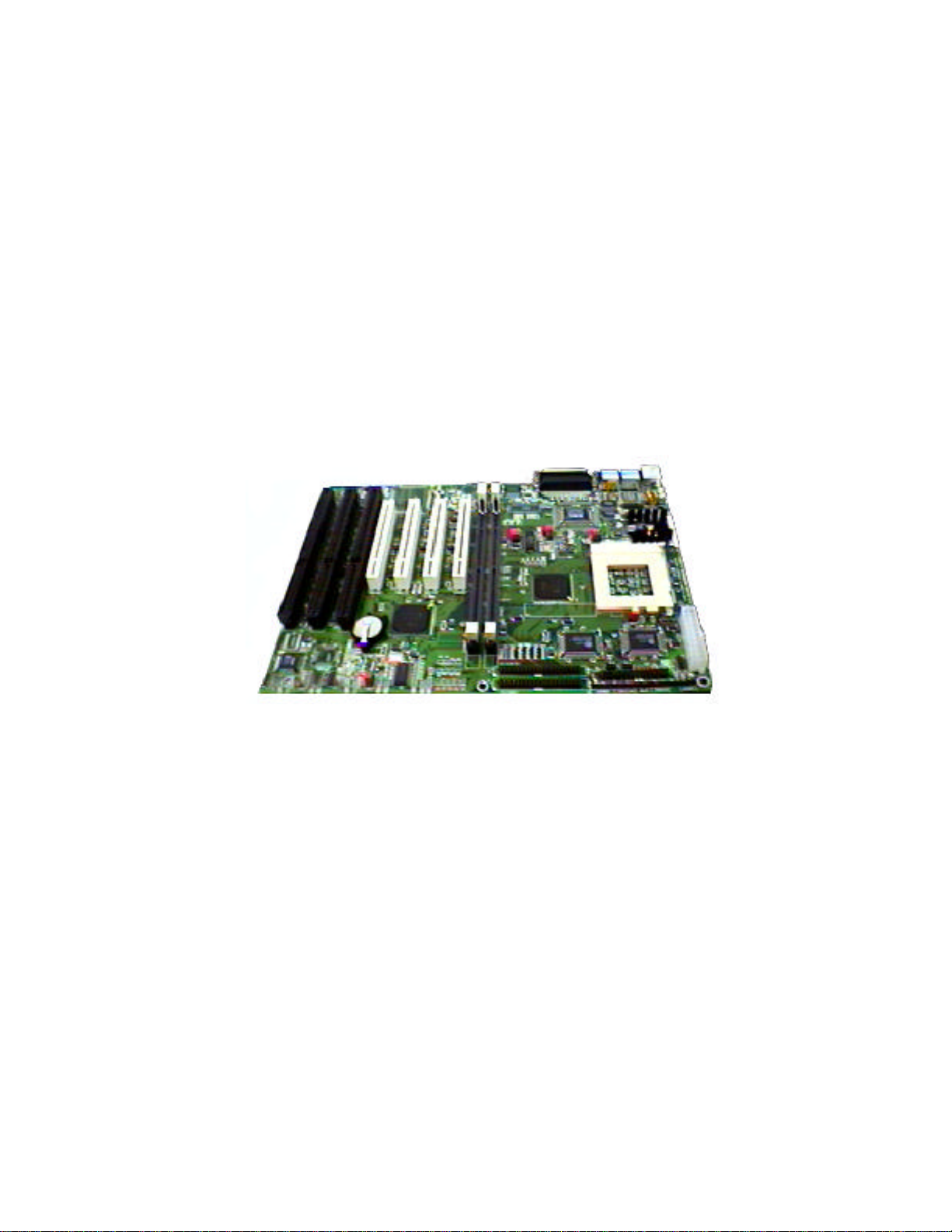
Yukon TX
Motherboard
User Manual
Version 2.1

2
USER'S NOTICE
No part of this product, including the product and software, may be reproduced,
transmitted, transcribed, stored in a retrieval system or translated into any language in
any form by any means without the express written permission of Seanix Technology
Inc (herein after referred to as Seanix) except documentation kept by the purchaser for
backup purposes.
Seanix provides this manual "as is" without warranty of any kind, either express or
implied, including but not limited to the implied warranties or conditions of
merchantability or fitness for a particular purpose. In no event shall Seanix be liable for
any loss or profits, loss of business, loss of use or data, interruption of business, or for
indirect, special, incidental, or consequential damages of any kind? even if Seanix has
been advised of the possibility of such damages arising from any defect or error in this
manual or product. Seanix may revise this manual from time to time without notice.
Products mentioned in this manual are mentioned for identification purposes only.
Product names appearing in this manual may or may not be registered trademarks or
copyrights of their respective companies.
The product name and revision number are both printed on the board itself. Manual
revisions are released for each design represented by the digit before and after the
period and for manual updates represented by the third digit in the manual revision
number. For updated BIOS, drivers, or product release information you may visit
Seanix’ home page at: http://www.seanix.com
Copyright 1997 Seanix Technology Inc. All rights reserved.
Trademarks
Seanix makes no warranty of any kind with regard to this material, including, but not
limited to, the implied warranties of merchantability and fitness for a particular purpose.
Seanix assumes no responsibility for any errors that may appear in this document.
Seanix makes no commitment to update nor to keep current the information contained
in this document. No part of this document may be copied or reproduced in any form or
by any means without prior written consent of Seanix.
Pentiumis a registered trademark of IntelCorporation.
AMI is a registered trademark of American Megatrends Inc.
Third-party brands and trademarks are the property of their respective owners.
Copyright 1997, Seanix.

3
TABLE OF CONTENTS
1.PRODUCT DESCRIPTION...................................................................................................................5
FEATURES OF THE YUKON TX MOTHERBOARD..............................................................................................5
MOTHERBOARD LAYOUT.............................................................................................................................6
CENTRAL PROCESSING UNIT .......................................................................................................................7
MEMORY...................................................................................................................................................7
CACHE MEMORY........................................................................................................................................7
IDE PERIPHERAL INTERFACE ......................................................................................................................7
SUPER I/O ................................................................................................................................................8
SYSTEM BIOS...........................................................................................................................................9
EXPANSION SLOTS...................................................................................................................................11
ONBOARD LAN........................................................................................................................................12
WAKE ON LAN HEADER............................................................................................................................13
KEYBOARD/MOUSE CONTROLLER ..............................................................................................................13
REAL-TIME CLOCK AND CMOS RAM.........................................................................................................14
FRONT PANEL CONNECTOR (J6)................................................................................................................14
FAN CONNECTORS...................................................................................................................................14
MAIN POWER CONNECTOR (J2).................................................................................................................14
MANAGEMENT EXTENTION COMPONENT .....................................................................................................15
LS-120 SUPPORT....................................................................................................................................15
SYSTEM SECURITY...................................................................................................................................15
2.INSTALLATION AND SETTINGS.......................................................................................................16
JUMPER SETTINGS ...................................................................................................................................16
CPU INSTALLATION..................................................................................................................................17
SYSTEM MEMORY INSTALLATION................................................................................................................18
BATTERY REPLACEMENT...........................................................................................................................18
EXPANSION CARD INSTALLATION................................................................................................................19
3.USING THE BIOS SETUP PROGRAM ..............................................................................................20
STANDARD CMOS SETUP ........................................................................................................................23
ADVANCED CMOS SETUP........................................................................................................................25
ADVANCED CHIPSET SETUP ......................................................................................................................27
POWER MANAGEMENT SETUP ...................................................................................................................28
PCI / PLUG AND PLAY SETUP....................................................................................................................31
PERIPHERAL SETUP .................................................................................................................................34
CPU CONFIGURATION SETUP ...................................................................................................................36
AUTO-DETECT HARD DISKS ......................................................................................................................37
CHANGE USER PASSWORD & CHANGE SUPERVISOR PASSWORD ..................................................................37
AUTO CONFIGURATION WITH OPTIMAL SETTINGS .........................................................................................37
AUTO CONFIGURATION WITH FAIL SAFE SETTINGS.......................................................................................37
SAVE SETTINGS AND EXIT.........................................................................................................................37
EXIT WITHOUT SAVING .............................................................................................................................38
UPGRADING THE BIOS.............................................................................................................................38
4.ERROR AND INFORMATION MESSAGES.......................................................................................39

4
BEEP CODES...........................................................................................................................................40
ERROR MESSAGES ..................................................................................................................................41
5.GLOSSARY.......................................................................................................................................43

5
1.Product Description
Congratulations on your purchase of the Yukon TX Motherboard. This motherboard supports
Pentium®processors and Pentium®processors with MMX™ technology.
Features of the Yukon TX Motherboard
•Intel Pentium®microprocessor running at 75, 90, 100, 120, 133, 150, 166, and
200MHz.
•Intel Pentium®MMX microprocessor running at 166, 200 and 233 MHz.
•ATX form factor motherboard.
•Intel 82430TX PCI set (2 chips).
•Support for two Dual-in-line memory modules (DIMMs) including Fast Page, EDO,
and SDRAM up to 512 MB.
•Supports 256-512K Pipeline Burst SRAM.
•Supports Ultra DMA IDE transfer rate up to 33MB/sec.
•Optional 10/100 Mbps 32-bit PCI LAN onboard, Wake on LAN support.
•AMI BIOS in a flash memory device that supports system setup and PCI auto-
configuration.
•Expansion slots for up to six add-in boards
Three dedicated PCI-bus slots
Two dedicated ISA-bus slots
One "shared" slot for either a PCI or an ISA add-in board
•Two High Speed RS-232-compatible serial ports.
•One multimode, Centronics-compatible parallel port (ECP/EPP & Normal SPP).
•USB support.
•PS/2 mouse support.
•PS/2 keyboard.
•Full support ACPI (Advanced Configuration and Power Interface) Rev. 1.0.

6
Motherboard Layout.

7
Central Processing Unit
The system is designed to operate with the Intel PentiumOR Intel PentiumMMX
microprocessors. A Zero Insertion Force (ZIF) socket 7 on the motherboard makes the
installation and removal of CPU’s an easy task. Please refer to the section on CPU
Installation in chapter 2 regarding the precautions necessary for performing this action.
The P54C Pentiumprocessor, in addition to its expanded data and addressing
capabilities, includes the following features:
•Onchip numeric coprocessor (compatible with the Intel486DX processor and
compliant with ANSI/IEEE standard 754-1985)
•Onchip 16 KB cache (8 KB for data, 8 KB for code)
•Burst-mode bus cycles
The PentiumMMX processor, in addition to the standard Pentium processor, includes
the following features:
•Better performance.
•Onchip 32 KB cache.
•57 extra instructions enhancing Multimedia operations.
Memory
The Yukon TX motherboard supports base (conventional) and extended memory.
Operating systems such as MS-DOS, MicrosoftWindows, OS/2, UNIX, and all
other application programs using base memory are supported.
The motherboard supports up to 512 MB of RAM memory. RAM is implemented by 5V
or 3V 168-pin dual in-line memory modules (DIMMs) in two DIMM sockets.
Cache Memory
The Pentium microprocessor includes 16KB/32KB of level 1 cache within the chip. The
82430TX PCI set includes a cache controller that supports direct-mapped cache
memory and supports a second level cache (L2) that uses Synchronous Pipeline Burst
SRAM onboard. Your motherboard will be fitted with either 256K or 512K of L2 cache.
IDE Peripheral Interface
The motherboard provides a high speed, 32-bit PCI/IDE interface. The PCI/IDE
interface supports:
•Up to four PCI/IDE devices
•Supports PIO Mode 0 to Mode 4

8
•Logical block addressing (LBA) of hard drives larger than 528 MB
•Extended Cylinder Head Sector (ECHS) translation modes
•ATAPI devices (such as CD-ROMs) on both IDE interfaces
•Ultra DMA/33 IDE support. Data transfer rate up to 33MB/sec.
Super I/O
The Plug and Play Super I/O supports the following logical devices:
1. High performance 2.88MB floppy disk controller with digital data separator, 1.44 MB
(3.5”) drives and 1.2 MB (5.25”) drives.
2. Printer Port with Printer mode, normal SPP mode, EPP mode and ECP mode.
3. Two Serial Ports with high speed 16C550 compatible enhanced UARTs.
These logical devices can be enabled or disabled individually by BIOS setting. The
Super I/O uses power saving circuitry to control power consumption. Each time a
logical device is disabled, its input gate is inhibited, output is tristated and input clock is
disabled. The net result is high performance and low power consumption.
•Plug and Play, Version 1.0a compatible to meet Win 95 logo requirement
built-in Resource Data ROM
16-bit address decoding
•2.88MB floppy disk controller
48mA direct output driver
Enhanced digital data separator
A and B drive may be swapped
supports two 360K, 720K, 1.2M, 1.44M, 2.88M floppy disk drives
•Multi-mode high performance parallel port
Standard mode -- bi-directional SPP
Enhanced mode -- EPP 1.7 and EPP 1.9 compatible
High Speed mode -- ECP, IEEE 1284 compliant
Backdrive current protection
Printer power-on damage protection
•Two Serial Port
Supports two 16C550 compatible enhanced serial ports
•ACPI support

9
System BIOS
BIOS, an acronym for Basic Input Output System, stands as the first link between
hardware and software in coordinating the startup configuration of computers. Plug and
play ready, AMIBlOS automatically configures the computer's hard drives, disk drives,
processors, chipsets, memory, and boot-up of the operating system.
The system BIOS, from AMI, provides ISA PnP and PCI PnP compatibility. The BIOS is
contained in a flash memory device. The BIOS provides the power-on self test (POST),
the system Setup program, a PCI and IDE auto-configuration.
The system BIOS is always shadowed. Shadowing allows any BIOS routines to be
executed from fast 32-bit onboard DRAM instead of from the slower 8-bit flash device.
1. Plug and Play Rev 1.0A support.
2. Boot Block Protection.
3. Auto detects Pipeline Burst SRAM and Cache size, IDE mode type and size.
4. Supports APM 1.2.
5. Supports DMI 2.0.
6. Supports USB.
7. Supports Booting from a Floppy drive, IDE device, CD-ROM, SCSI, Floptical or
Network.
8. 1MB/2MB flash EEPROM for easy BIOS upgrade.
PCI IDE
1. “Ultra DMA/33” Synchronous DMA IDE support.
2. Meets Microsoft requirement for PC97, cable select for master/slave configuration.
3. Fully compatible with PCI spec.V2.1.
4. Supports PCI Bus Mastering.
5. Supports Mode 3 and Mode 4 for Enhanced IDE specification.
6. Supports Multi-word DMA mode 0,1,2.
7. Supports PCI burst Read/Write.
8. Supports Primary and Secondary IDE for a total of 4 drives.
9. IDE CD-ROM support.
PCI Auto-configuration
The PCI auto-configuration works in conjunction with the Setup program to support
using PCI add-in boards in the system. When you turn on the system power after
installing a PCI board, the BIOS automatically configures interrupts, DMA channels, I/O
space, and so on. Since PCI add-in boards use the same interrupt resources as ISA

10
add-in boards, you must specify the interrupts used by non PnP ISA boards in the
Setup program. Chapter 2 tells how to use the Setup program. The PCI auto-
configuration program complies with version 2.1 of the PCI BIOS specification.
IDE Auto-configuration
When an IDE drive is installed in the system, the IDE auto-configuration function
automatically detects and configures the drive for operation in the system. This function
eliminates the need to enter the Setup program after you install an IDE drive.
ISA Plug and Play Capability
This provides auto-configuration of Plug and Play ISA cards and resource management
for legacy (non Plug and Play) ISA cards.
Universal Serial Bus (USB) Support
AMIBIOS 97 stands as the first BIOS to offer full support for the Universal Serial Bus
(USB) standard. The USB technology enables users to quickly and easily attach and
reconfigure a wide range of peripheral devices, from keyboards to printers to telephony
devices. With comprehensive support for both USB host controllers and USB devices,
AMIBIOS 97 offers the ability to fully utilize USB technology now. Support for Intel's
Universal Host Controller Interface (UHCI) and Open Host Controller Interface (OHCI)
ensure compatibility and usability well into the future. AMI's USB-WARE serves as a
total firmware system solution for anyone using a USB micro-controller.
AMIBIOS 97 offers advanced features for ease-of-use and flexibility: Full Hub Support
Full Bus Enumeration Dynamic Hard Attach/Detach Legacy Keyboard and Mouse
Support.
The motherboard features two USB ports as a factory installed option. The ports permit
the direct connection of two USB peripherals without an external hub. If more
devices are required, an external hub can be connected to either of the built-in ports
This motherboard fully supports the standard Universal Host Controller Interface
(UHCI) and uses standard software drivers that are UHCI compatible. Features of
the USB include:
•Self-identifying, hot pluggable peripherals.
•Automatic Mapping of function to driver and configuration.
•Support for Isochronous and Asynchronous transfer types over the same set of
wires.
•Support for up to 127 physical devices.
•Guaranteed bandwidth and low latencies appropriate for telephony, audio, and other
applications.
Error handling and fault recovery mechanisms built into protocol.

11
BIOS Upgrades
Because the BIOS is stored in a flash memory device, you can easily upgrade the BIOS
without having to disassemble the system. The flash upgrade process can be done by
running a utility from a diskette or hard disk, or over a network.
WARNING
For information about the latest BIOS update for Yukon TX, contact your service
representative.
Expansion Slots
The board has three 16-bit ISA and four PCI expansion slots. One expansion slot is a
"combination" slot and can be used by either a PCI or an ISA board, enabling you to
install a maximum of six add-in boards.
PCI Slots:
At the highest rate using a 32 bit CPU the PCI bus transfers data at 132 MB/second.
Part of the reason for high transfer rates is the PCI bus can operate concurrently with
the processor bus; it doesn’t override it. The CPU can be processing data in an external
cache while the PCI bus is busy transferring information between other parts of the
system. Another key feature of the PCI bus is it’s plug and play capabilities which
eliminates the need for jumper and dip switches for configuring a PCI card.
The PCI slots on the Yukon TX motherboard are labeled as:
SLOT 1 – SHARED
SLOT 2 – MASTER
SLOT 3 – MASTER
SLOT 4 – MASTER
***THIS IS INCORRECT BECAUSE SLOT 4 IS ALSO SHARED (see below for an
explanation).
The PCI slots on the Yukon TX motherboard should be labeled as follows:
SLOT 1 – SHARED
SLOT 2 – MASTER
SLOT 3 – MASTER
SLOT 4 – SHARED
Slot 1 – Shared:
This slot is “shared” with the resources used by the integrated LAN card. If the LAN
card is integrated then slot 1 is unavailable. This is because there can only be 4 PCI

12
devices in use per PCI bridge. When integrated LAN is not installed and slot 1 is
available the slot functions as a normal bus-mastering PCI slot.
Slot 2 & 3 – Master:
These two slots do not share resources with any other device and are fully functional
bus-mastering PCI slots.
Slot 4 – Shared:
This slot shares its resources in two ways: first, you can either use PCI slot 4 or ISA slot
1 but not both at the same time. Second, if you use the PCI slot 4 it shares resources
with the USB port resources. USB performs bus mastering and will conflict with a bus
mastering PCI card in slot 4. A non-bus-mastering card like a video card will function
properly in slot 4 with USB enabled. The only way to use a bus-mastering card
effectively in slot 4 is to disable the USB port in the CMOS.
Onboard LAN
The onboard LAN for the TX motherboard is driven by the Digital Semiconductor 21143
10/100 Mb/s Ethernet LAN Controller. It therefore supports 10Base-T and 100Base-TX
Fast Ethernet connections.
The RJ45 network connector at the back of your system requires a category 5 (CAT5)
unshielded twisted pair (UTP) 2-pair cable for a 100-Mb/s network connection or a
category 3 (CAT3), or higher, UTP 2-pair cable for a 10-Mb/s network connection.
The 21143 has the following features:
Contains onchip PCS and scrambler / descrambler for CAT5
Supports full auto detection (NWAY)
Contains large independent receive and transmit FlFO’s
Supports PC! read multiple, read line, and write and invalidate commands
Includes a powerful onchip direct memory access (DMA) with programmable
burst size, providing low CPU utilization
Supports an unlimited PCI burst
Supports early interrupt on transmit and receive
Contains a variety of flexible address filtering modes
Supports PCI clock speed frequency from dc to 33 MHz; network operation with
PCI clock from 20 MHz to 33 MHz
Supports automatic loading of subvendor ID information structure (CIS) pointer from
serial ROM to configuration registers
Supports big or little endian byte ordering for buffers and descriptors
Supports full-duplex operation on both MII / SYM and 10BASE-T ports

13
Implements low-power management with two power-saving modes (sleep and
snooze)
Provides internal and external loopback capability on all network ports
Provides LED support for various network activity indications
Supports interrupts from two general-purpose pins
Implements test-access port (JTAG-compatible) with boundary-scan pins
Implements low-power, 3.3-V CMS technology
Takes less than 70 mA of supply current after power-up
Enables automatic detection and correction of 10BASE-T receive polarity
Supports auto detection between 10BASE-T, AUl, and MII / SYM ports
Supports IEEE 802.3 auto negotiation algorithm of full-duplex and half-duplex operation
for 10 and 100 Mb/s Implements unique, intelligent arbitration between DMA channels
to minimize underflow or overflow
Supports two network ports: 10BASE-T (10 Mb/s) and MII/ SYM (10/100 Mb/s)
Contains a 4-bit, general-purpose programmable register and corresponding I/O pins
Supports IEEE 802.3 and ANSI 8802-3 Ethernet standards
The onboard LAN can be enabled or disabled using JP18 and JP20 jumpers:
JP18 and JP20 ON – LAN onboard enabled.
JP18 and JP20 OFF – LAN onboard disabled.
The drivers for the LAN chipset are available on the Seanix CD supplied with your
computer in the following directory: Mthrbrds\Yukon_TX. If you do not have these
drivers then contact your dealer for a replacement copy.
Wake on LAN Header
The header, JP19, is used to implement the Wake on LAN feature when the onboard
LAN is disabled. Connect this header to a PCI LAN adapter that supports the Wake on
LAN feature. The adapter monitors network traffic. When the adapter detects a ‘Magic
Packet’, it asserts a signal through the Wake on LAN header to wake up the computer.
This signal can wake up the computer only when the AC power cord is still plugged into
the socket and the computer is turned off using the Standby Power button.
Keyboard/Mouse Controller
The I/O controller stores the keyboard and mouse controller code.

14
Real-Time Clock and CMOS RAM
Yukon TX motherboard’s real time clock is built into the chipset.
The time for the clock and the CMOS values can be set by using the system BIOS Setup
program, described in Chapter 3.
Front Panel Connector (J6)
INFRARED Pins 1 - 6, not currently used.
SLP Pins 8 & 9, connected to Standby Power Switch via twisted pair cable
(orange/white).
RST Pins 10 & 11, connected to Reset Switch via twisted pair cable
(orange/white).
HDLED Pins 14 & 15, connected to the HDD LED via twisted pair cable
(red/white).
PWRLED Pins 17 & 19, connected to the Power LED via twisted pair cable
(white/green respectively).
SPEAKER Pins 23, 25 & 26, connected to the case speaker via twisted pair cable
(red/black).
Fan Connectors
Two fan connectors, J4 & J7, are provided for connecting either a second case fan or a
CPU fan. The pin assignment for these connectors are as follows:
Pin 1 – Ground.
Pin 2 - +12V.
Pin 3 – Sensor
Main Power Connector (J2)
The power supply connector is an ATX style twenty-pin male connector. The connector
from the power supply can fit into the socket in only one direction.

15
Management Extention Component
The optional Management Extension component (National Semiconductor LM78)
provides low-cost instrumentation capabilities designed to reduce the total cost of
owning a PC when used with LANDesk Client Manager. The hardware implementation
is a single-chip ASIC. Feature include:
An integrated ambient temperature sensor
Fan speed sensors.
Power supply voltage monitoring to detect levels above or below acceptable values.
Registers for storing POST hardware test results and error codes.
Remote reset capabilities from a remote peer or server through LANDesk Client
Manager, Version 3.0 and service layers (when available)
When suggested ratings for temperature, fan speed, or voltage are exceeded, an
interrupt is activated. The Management Extension component (LM78) connects to the
ISA bus as an 8-bit I/O mapped device.
LS-120 Support
LS-120 MB Diskette technology enables users to store 120 MB of data on a single, 3.5
Inch removable diskette. LS-120 technology is backward (both read and write)
compatible with 1.44 MB and 720 KB DOS-formatted diskettes and is supported by
Windows 95 and Windows NT operating systems.
The Yukon TX motherboard allows connection of an LS-120 compatible drive and a
standard 3.5-inch diskette drive. The LS-120 drive can be configured as a boot device,
if selected in the BIOS setup utility.
System Security
The BIOS provides a password option that you can enable through the Setup program
(see Chapter 3).

16
2.Installation and Settings
CAUTION
Electrostatic discharge (ESD) can damage components. Perform the procedures
described in this chapter only at an ESD workstation. If such a station is not
available, you can provide some ESD protection by wearing an antistatic wrist
strap and attaching it to a metal part of the computer.
Jumper Settings
The motherboard contains configuration jumpers that make it possible to change the
system configuration. Normally, the only time you will ever change a jumper is if you
need to:
•Change the system operating speed.
•Change the type of CPU used.
•Change the DRAM voltage.
/NOTE
A jumper is a small plastic-encased conductor that slips over jumper pins. To
change a jumper setting, use a pair of fine needle-nosed pliers to remove the
jumper from its current location and slide it onto the new pins to obtain the desired
setting.
CAUTION
Do not squeeze the pliers or other tool you use to remove a jumper, or you might
bend or break the pins.

17
CPU Speed Jumpers
These jumpers set the CPU frequencies and the clock ratio. The jumpers should be
changed only when you upgrade the CPU.
JP3 JP4 JP5 JP8 JP9 JP11
133 2-3 Open Open Open Closed Open
150 2-3 Closed Closed Closed Open Open
166 2-3 Closed Open Open Closed Open
180 1-2 Closed Closed Closed Open Open
200 1-2 Closed Open Open Closed Closed
233 1-2 Open Open Open Closed Open
This table is screen printed on the motherboard.
CPU Type Selection
These jumpers are used to select between standard Intel Pentium CPUs (P54C) and the Intel
Pentium MMX CPUs (P55C).
CPU Type JP12 JP13 JP14
MMX 2-3 2-3 2-3
P54C 1-2 1-2 1-2
This table is screen printed on the motherboard.
DRAM Voltage Selection.
Set these jumpers for 5V if you have a P54C CPU and for 3.3V if you have a P55C CPU.
JP6 JP7
5V * Closed Open
3.3V Open Closed
* Default setting
CPU Installation
The motherboard provides a 321-pin ZIF Socket 7 that is backwards compatible with
ZIF Socket 5 processors. The CPU that came with your system should have a low
profile heatsink & fan attached to it to prevent overheating. If this is not the case then
purchase a fan before you turn on your system. Apply thermal jelly to the CPU top and
then install the heatsink & fan onto the CPU. Some heatsinks with large fins do not
require additional fans and may have been used in your system.
WARNING: Without a heatsink & fan the CPU will overheat and cause damage to
both the CPU and the motherboard.

18
To install a CPU remove the case cover, locate the ZIF
socket and open it by first pulling the lever sideways
away from the socket then upwards to a 90-degree right
angle. Insert the CPU into the ZIF socket with the
correct orientation as shown. The ZIF socket has a
blank area where one hole is missing from that corner
of the square array of pin holes, align the notched
corner of the CPU (with the white dot as your guide)
with this corner. Because the CPU has a corner pin for
three of the four corners, the CPU will only fit in the one
orientation as shown. (The picture is for reference only;
your CPU’s face will be covered by the heatsink and
fan). With the added weight of the CPU fan, no force is required to insert the CPU.
Once completely inserted, press down on the fan and close the socket’s lever.
IMPORTANT: You must set the jumpers for "CPU Speed" depending on the CPU that
you installed.
System Memory Installation
The system board contains two 168-pin, tin lead DIMM sockets. You can configure the
system memory up to 512MB. The sockets are arranged as banks 1 and 2.
When adding memory, follow these guidelines:
•The computer automatically detects the installed memory, so it doesn’t matter which
bank is used.
•When adding DIMMs, use only tin lead, 168-pin DIMMs, either EDO or SDRAM
DIMMs are supported. DIMM modules commonly available include 16MB, 32MB
and 64MB. This motherboard also supports a 48MB DIMM specially designed by
Seanix.
Battery Replacement
When your computer is turned off, a lithium battery keeps the time-of-day clock and the
values in CMOS RAM current. Figure 12 shows the location of the battery.
The battery should last about seven years. When the battery begins to die, it loses
voltage; when the voltage drops below a certain level, the Setup program settings
stored in CMOS RAM (for example, the date and time) might not be accurate. Replace
the battery with an equivalent one.
If your local ordinances permit, you may dispose of individual batteries as normal trash.
Do not expose batteries to excessive heat or fire. Keep all batteries away from children.

19
CAUTION
Danger of explosion if the battery is incorrectly replaced. Replace only with the same or
equivalent type recommended by the equipment manufacturer. Discard used batteries
according to manufacturer's instructions.
Expansion Card Installation
The computer system should be switched off and the power cord removed before
installing any expansion cards into the system. Failure to do so may cause severe
damage to both your motherboard and expansion cards.
Before installing an expansion card, read it’s documentation regarding any hardware or
software settings that may be required to set up your specific card.
•Set any necessary jumpers on the expansion card.
•Remove your computer system’s cover.
•Identify the type of slot where the expansion card will be installed and isolate one of
the vacant slots for your card.
•Remove the blanking bracket for that slot and retain for possible future use.
•Carefully align the cards edge connector with the motherboard slot and press down
firmly to seat the card in the slot, a rocking motion usually makes this easier.
•Secure the cards’ back-plate with the screw you removed earlier.
•Replace the computer system’s cover.
•Plug in the power cord and proceed to install any drivers or software needed for that
card.

20
3.Using the BIOS Setup Program
This chapter tells how to use the Setup program that is built into the BIOS. The Setup
program makes it possible to change configuration information (such as the types of
peripherals that are installed) and the boot-up sequence for the system. The Setup
information is stored in CMOS random access memory (RAM) and is backed up by a
battery when power is off.
If the board does not operate as described here, see Chapter 3 for problem
descriptions and error messages.
Record the Setup Configuration
To make sure you have a reference to the Setup values for your system, we
recommend you to write down the current settings and keep this record up-to-date.
AMI BIOS Setup Menu Overview
The AMI BIOS Setup program is easy to use and can be controlled by the keyboard.
Enter the AMI BIOS Setup main menu as follows:
1. Turn on or reboot your system.
2. When the message “Hit <DEL>, if you want to run SETUP” appears, press the
<DEL> key to enter the BIOS setup program. The AMI BIOS setup utility (Main
Menu) screen, as illustrated on the next page, will appear.
Table of contents
Other Seanix Motherboard manuals