Seanix CA810 User manual
CA810
Motherboard
Product Guide
Order Number: 738718-001

Revision History
Revision Revision History Date
-001 Final version. April 1999
If an FCC declaration of conformity marking is present on the board, the following statement applies:
FCC Declaration of Conformity
This device complies with Part 15 of the FCC Rules. Operation is subject to the following two conditions: (1) this device
may not cause harmful interference, and (2) this device must accept any interference received, including interference that
may cause undesired operation.
For questions related to the EMC performance of this product, contact:
Intel Corporation
5200 N.E. Elam Young Parkway
Hillsboro, OR 97124
1-800-628-8686
This equipment has been tested and found to comply with the limits for a Class B digital device, pursuant to Part 15 of the
FCC Rules. These limits are designed to provide reasonable protection against harmful interference in a residential
installation. This equipment generates, uses, and can radiate radio frequency energy and, if not installed and used in
accordance with the instructions, may cause harmful interference to radio communications. However, there is no guarantee
that interference will not occur in a particular installation. If this equipment does cause harmful interference to radio or
television reception, which can be determined by turning the equipment off and on, the user is encouraged to try to correct
the interference by one or more of the following measures:
•Reorient or relocate the receiving antenna.
•Increase the separation between the equipment and the receiver.
•Connect the equipment to an outlet on a circuit other than the one to which the receiver is connected.
•Consult the dealer or an experienced radio/TV technician for help.
Canadian Department of Communications Compliance Statement:
This digital apparatus does not exceed the Class B limits for radio noise emissions from digital apparatus set out in the
Radio Interference Regulations of the Canadian Department of Communications.
Le présent appareil numerique német pas de bruits radioélectriques dépassant les limites applicables aux appareils
numériques de la classe B prescrites dans le Réglement sur le broullage radioélectrique édicté par le ministére des
Communications du Canada.
Disclaimer
Intel Corporation (Intel) makes no warranty of any kind with regard to this material, including, but not limited to, the implied
warranties of merchantability and fitness for a particular purpose. Intel assumes no responsibility for any errors that may
appear in this document. Intel makes no commitment to update nor to keep current the information contained in this
document. No part of this document may be copied or reproduced in any form or by any means without prior written
consent of Intel.
An Intel product, when used in accordance with its associated documentation, is "Year 2000 Capable" when, upon
installation, it accurately stores, displays, processes, provides, and/or receives date data from, into, and between the
twentieth and twenty-first centuries, including leap year calculations, provided that all other technology used in combination
with said product properly exchanges date data with it.
†Third-party brands and trademarks are the property of their respective owners.
Copyright 1999, Intel Corporation. All Rights Reserved

iii
Contents
1 Motherboard Features
Feature Summary.................................................................................................................7
Components......................................................................................................................... 8
Microprocessor..................................................................................................................... 9
Main Memory ....................................................................................................................... 9
Graphics Subsystem.......................................................................................................... 10
Intel 82810 GMCH..................................................................................................... 10
GMCH DC-100 (Optional).......................................................................................... 11
Audio Subsystem ............................................................................................................... 12
Creative Sound Blaster AudioPCI 64V Audio Controller ............................................ 12
Crystal Semiconductor CS4297 Stereo Audio Codec................................................ 12
Audio Connectors...................................................................................................... 12
Audio Drivers and Utilities.......................................................................................... 13
Speaker.............................................................................................................................. 13
LAN Subsystem (Optional)................................................................................................. 13
Intel82559 LAN Controller ...................................................................................... 13
LAN Subsystem Software.......................................................................................... 14
RJ-45 LAN Connector LEDs...................................................................................... 14
PCI Enhanced IDE Interface .............................................................................................. 14
Input/Output (I/O) Controller............................................................................................... 15
Real-Time Clock.................................................................................................................15
USB Support ...................................................................................................................... 16
BIOS .................................................................................................................................. 16
Intel82802AB Firmware Hub (FWH) ....................................................................... 16
PCI Auto Configuration.............................................................................................. 16
IDE Auto Configuration.............................................................................................. 16
Security Passwords................................................................................................... 17
Expansion Slots.................................................................................................................. 17
Power Management Features............................................................................................ 17
Wake on LAN Technology......................................................................................... 18
Instantly Available Technology .................................................................................. 19
Resume on Ring........................................................................................................ 20
Battery................................................................................................................................ 20
2 Installing and Replacing Motherboard Components
Before You Begin............................................................................................................... 21
How to Install and Remove the Motherboard...................................................................... 22
How to Install a Motherboard Support Standoff.................................................................. 23
How to Remove the Processor........................................................................................... 27
How to Install Memory........................................................................................................ 27
How to Remove Memory.................................................................................................... 30
How to Replace the Battery................................................................................................ 30
How to Connect IDE Drives................................................................................................ 32
How to Clear the Passwords .............................................................................................. 32

CA810 Motherboard Product Guide
iv
How to Set Jumpers........................................................................................................... 33
BIOS Setup Configuration Jumper Block................................................................... 34
USB Port 0 Configuration Jumper Block (Optional) ................................................... 34
3 Using the Setup Program
BIOS Setup Program Modes.............................................................................................. 35
Function Keys..................................................................................................................... 36
Accessing the Setup Program............................................................................................ 36
Upgrading the BIOS .................................................................................................. 37
Obtaining the BIOS Upgrade File .............................................................................. 37
Recording the Current BIOS Settings........................................................................ 37
Creating a Bootable Diskette..................................................................................... 38
Creating the BIOS Upgrade Diskette......................................................................... 38
Upgrading the BIOS........................................................................................................... 39
Recovering the BIOS.......................................................................................................... 39
Changing the BIOS Language............................................................................................ 40
4 Technical Reference
Motherboard Connectors.................................................................................................... 41
Back Panel Connectors............................................................................................. 42
Midboard Connectors ................................................................................................ 43
Front Panel Connectors............................................................................................. 44
Motherboard Resources..................................................................................................... 45
Memory Map......................................................................................................................45
DMA Channels...................................................................................................................45
I/O Map.............................................................................................................................. 46
Interrupts............................................................................................................................ 48
A Error Messages
BIOS Beep Codes.............................................................................................................. 49
BIOS Error Messages ........................................................................................................ 49
B Regulatory and Integration Information
Regulatory Compliance...................................................................................................... 51
Product Certification Markings............................................................................................ 52
Installation Precautions ...................................................................................................... 52
Installation Instructions.......................................................................................................53
Ensure Electromagnetic Compatibility (EMC)............................................................ 53
Ensure Chassis and Accessory Module Certifications............................................... 53
Prevent Power Supply Overload................................................................................ 54
Place Battery Marking on the Computer.................................................................... 54
Use Only for Intended Applications............................................................................ 54
Figures
1. Motherboard Components............................................................................................... 8
2. Using the Wake on LAN Technology Connector............................................................ 18
3. Location of Standby Power Indicator LED..................................................................... 19
4. Mounting Screw Holes................................................................................................... 22

Contents
v
5. Motherboard Support Standoff in a Standard ATX Chassis........................................... 23
6. Raising the Socket Handle............................................................................................ 24
7. Inserting the Processor into the Socket......................................................................... 24
8. Closing the Handle........................................................................................................ 25
9. Attaching the Heatsink to the Processor........................................................................ 25
10. Attaching the Fan Heatsink Clip .................................................................................. 26
11. Connecting the Processor Fan Cable to the Processor Fan Connector....................... 26
12. Installing a DIMM......................................................................................................... 29
13. Removing the Battery.................................................................................................. 31
14. Location of Configuration Jumper Block...................................................................... 33
15. Connector Groups....................................................................................................... 41
16. Back Panel Connectors and Indicators........................................................................ 42
17. Midboard Connectors.................................................................................................. 43
18. Front Panel Connectors............................................................................................... 44
Tables
1. Processors Supported by the Motherboard.................................................................... 9
2. Intel 82810 GMCH Refresh Rates................................................................................ 11
3. RJ-45 LAN Connector LEDs........................................................................................ 14
4. Jumper Settings for BIOS Setup Program Modes........................................................ 34
5. USB Port 0 Configuration Jumper Settings.................................................................. 34
6. Setup Menu Screens ................................................................................................... 36
7. Setup Function Keys.................................................................................................... 36
8. System Memory Map................................................................................................... 45
9. DMA Channels............................................................................................................. 45
10. I/O Map........................................................................................................................ 46
11. Interrupts ..................................................................................................................... 48
12. Beep Codes................................................................................................................. 49
13. BIOS Error Messages.................................................................................................. 49
14. Safety Regulations....................................................................................................... 51
15. EMC Regulations......................................................................................................... 51

CA810 Motherboard Product Guide
vi

7
1 Motherboard Features
Feature Summary
Form Factor MicroATX (9.6 inches by 9.6 inches)
Processor Support for Intel®Celeron™processor, in a 370-pin Plastic Pin Grid Array
(PPGA) package, with 66-MHz host bus speed
Chipset The Intel®82810 chipset consisting of:
•Intel®82810 Graphics/Memory Controller Hub (GMCH)
•Intel®82801AA I/O Controller Hub (ICH)
•Intel®82802AB 4 Mbit Firmware Hub (FWH)
Memory •Two 168-pin dual inline memory module (DIMM) sockets
•Support for up to 512 MB of 100-MHz, non-ECC, unbuffered synchronous
DRAM (SDRAM)
16 MB and 256 MB using 16 MB/64 Mbit technology
512 MB using 128 Mbit technology
•Support for serial presence detect (SPD) and non-SPD DIMMs
I/O Control SMSC LPC47B272 super I/O controller
Peripheral Interfaces •Two serial ports (header only for second serial port)
•Two Universal Serial Bus (USB) ports
•One parallel port
•PS/2†keyboard
•PS/2 mouse
Audio •Creative Sound Blaster†AudioPCI 64V audio controller
•Crystal Semiconductor CS4297 AC ’97 stereo audio codec
•Sony/Phillips Digital Interface Format (S/P-DIF) connector with Creative Sound
Blaster AudioPCI 64V audio subsystems (optional)
Video Intel 82810 Graphics/Memory Controller Hub (integrated in the chipset)
Intel 82810 DC-100 Graphics/Memory Controller Hub (optional)
Expansion capabilities Four PCI slots
Power Management •Supports Advanced Power Management (APM)
•Supports Advanced Configuration and Power Management Interface (ACPI)
including Suspend to RAM (STR)
BIOS •Intel/AMI BIOS
•Intel 82802AB Firmware Hub (FWH) 4 Mbit flash memory
Other features •Speaker
•SCSI HD Activity LED connector (optional)
•Hardware monitor (optional)
•Chassis intrusion detection (optional)
•Enhanced diagnostics LEDs (optional)
•Intel®82559 PCI LAN controller with RJ-45 LAN connector (optional)
✏NOTE
For information about Intel
®
motherboards, including technical product specifications, BIOS
upgrades, and device drivers, go to the Intel World Wide Web site at:
http://support.intel.com/support/motherboards/desktop

CA810 Motherboard Product Guide
8
Components
Figure 1 shows the major components on the motherboard.
OM07766
F I
GEB
L
J
K
M
N
P
AA XQSZ T R
EE
CC
JJ
KK
II
FF
DD
HH
A
LL
H
V
GG
D
C
U
W
BB
Y
O
A Crystal Semiconductor CS4297 audio codec T Power supply connector
B ATAPI-style CD-ROM connector U Fan 1 (chassis) connector
C Video source line in connector (optional) V USB front panel connector (optional)
D Legacy CD-ROM connector (optional) W Battery
E Serial port B header X Front panel connector
F Auxiliary line in connector (optional) Y SCSI HD Activity LED connector (optional)
G Telephony connector (optional) Z Intel 82802AB Firmware Hub (FWH)
H Enhanced diagnostics LEDs (optional) AA Speaker
I Back panel connectors BB Alternative 1x3 front panel power LED connector
J Intel 82559 LAN controller (optional) CC Wake on LAN†technology connector (optional)
K Fan 3 (processor) connector DD SMSC LPC47B272 super I/O controller
L 370-pin PPGA processor socket EE Chassis intrusion connector (optional)
M Intel 82810 Graphics/Memory Controller Hub
(GMCH) FF Configuration jumper block
N DIMM sockets GG USB front panel jumper block (optional)
O Hardware monitor (optional) HH Creative Sound Blaster AudioPCI 64V audio
controller
P Fan 2 connector (optional) II Intel 82801AA I/O Controller Hub (ICH)
Q Secondary IDE connector JJ Sony/Phillips Digital Interface Format connector
(optional)
R Primary IDE connector KK Video memory (optional)
S Diskette drive connector LL PCI slots
Figure 1. Motherboard Components

Motherboard Features
9
✏NOTE
Components labeled optional do not come on all CA810 motherboards.
Microprocessor
The motherboard supports the 370-pin PPGA socketed Celeron processors listed in Table 1. All
supported onboard memory can be cached.
Table 1. Processors Supported by the Motherboard
Processor Speed Host Bus Frequency Cache Size
466 MHz
433 MHz
400 MHz
366 MHz
333 MHz
300A MHz
66 MHz
66 MHz
66 MHz
66 MHz
66 MHz
66 MHz
128 KB
128 KB
128 KB
128 KB
128 KB
128 KB
For the latest information on processor support for the CA810 motherboard, refer to the Intel
boxed motherboard web site at:
http://support.intel.com/support/motherboards/desktop/
For instructions on installing or upgrading the processor, see Chapter 2.
Main Memory
The motherboard has two sockets for installing DIMMs. Minimum memory size is 32 MB;
maximum memory size is 512 MB. Due to the video requirements of the CA810 motherboard,
minimum memory for the Windows NT†4.0 operating system is 64 MB. For optimal video
performance, it is recommended that 64 MB of memory be installed. See Chapter 2 for types of
memory supported and installation instructions.
All supported onboard memory is cacheable.
✏NOTE
Some of the system memory is dedicated to video.

CA810 Motherboard Product Guide
10
Graphics Subsystem
The graphics subsystem features the Intel 82810 Graphic/Memory Controller Hub (GMCH).
Visit Intel’s World Wide Web site for information about graphics drivers:
http://support.intel.com/support/motherboards/desktop/
Intel 82810 GMCH
The Intel 82810 GMCH supports the following features:
•Integrated graphics controller
3-D Hyper Pipelined architecture
Full 2-D hardware acceleration
Motion video acceleration
•3-D graphics visual and texturing enhancements
•Display
Integrated 24-bit 230 MHz RAMDAC
DDC2B compliant
•Video
Hardware motion compensation for software MPEG2 decode
•Integrated graphics memory controller

Motherboard Features
11
Table 2 lists the refresh rates supported by the CA810 motherboard.
Table 2. Intel 82810 GMCH Refresh Rates
Resolution Color 60 (Hz) 70 (Hz) 72 (Hz) 75 (Hz) 85 (Hz)
640x200 16 x
640x350 16 x
640x400 256 x x x x
64 K x x x x
16 M x
640x480 16 x x x x
256xxxxx
32 K x x x
64Kxxxxx
16Mxxxxx
800x600 256 x xxxx
32 K x x x
64Kxxxxx
16Mxxxxx
1024x768 256 x x x x
32 K x x x
64Kxxxxx
16Mxxxxx
1056x800 16 x
1280x1024 256 x xxxx
32 K x x
64Kxxxxx
16Mxxxxx
GMCH DC-100 (Optional)
In addition to all the features of the GMCH, the optional GMCH DC-100 supports 4 MB of
display cache on the motherboard.

CA810 Motherboard Product Guide
12
Audio Subsystem
The audio subsystem consists of these devices:
•Creative Sound Blaster AudioPCI 64V digital controller
•Crystal Semiconductor CS4297 AC ’97 stereo audio codec
•Back panel and onboard audio connectors
Creative Sound Blaster AudioPCI 64V Audio Controller
The Creative Sound Blaster AudioPCI 64V audio controller features:
•Interfaces to the PCI bus as a Plug and Play device
•100% DOS legacy compatible
•Access to main memory (through the PCI bus) for wavetable synthesis support – does not
require a separate wavetable ROM device
•PC 98 and PC 99 compliant
•Optional Sony/Phillips digital interface format (S/P-DIF)
Crystal Semiconductor CS4297 Stereo Audio Codec
The Crystal Semiconductor CS4297 stereo audio codec features:
•High performance 18-bit stereo full-duplex audio codec with up to 48 kHz sampling rate
•Connects to the Sound Blaster AudioPCI 64V using a five-wire digital interface
Audio Connectors
The audio connectors include the following:
•CD-ROM (legacy-style 2 mm connectors)
•ATAPI-style connectors
CD-ROM audio
Auxiliary line in
Telephony (optional)
Video line in (optional)
•Back panel connectors
Line out
Line in
Mic in
MIDI/Game Port
✏NOTE
The line out connector, located on the back panel, is designed to power either headphones or
amplified speakers only. Poor audio quality may occur if passive (non-amplified) speakers are
connected to this output.

Motherboard Features
13
Audio Drivers and Utilities
Audio drivers and utilities are available from Intel’s World Wide Web site:
http://support.intel.com/support/motherboards/desktop
Speaker
A 47 Ωinductive speaker is mounted on the motherboard. The speaker provides audible error
code (beep code) information during the power-on self test (POST).
LAN Subsystem (Optional)
The Intel 82559 Fast Ethernet Wired for Management (WfM) PCI LAN subsystem provides both
10Base-T and 100Base-TX connectivity. Features include:
•32-bit, 33 MHz direct bus mastering on the PCI bus
•Shared memory structure in the host memory that copies data directly to/from host memory
•10Base-T and 100Base-TX capability using a single RJ-45 connector with connection and
activity status LEDs
•IEEE 802.3µ Auto-Negotiation for the fastest available connection
•Jumperless configuration; the LAN subsystem is completely software-configurable
Intel82559 LAN Controller
The Intel 82559 PCI LAN controller’s features include:
•CSMA/CD Protocol Engine
•PCI bus interface
•DMA engine for movement of commands, status, and network data across the PCI bus
•Integrated physical layer interface, including:
•Jumperless configuration; the LAN subsystem is completely software-configurable
Complete functionality necessary for the 10Base-T and 100Base-TX network interfaces;
when in 10 Mbit/sec mode, the interface drives the cable directly
A complete set of Media Independent Interface (MII) management registers for control
and status reporting
802.3µ Auto-Negotiation for automatically establishing the best operating mode when
connected to other 10Base-T or 100Base-TX devices, whether half- or full-duplex capable
•Integrated power management features, including:
Support for APM
Support for Wake on LAN technology
Support for ACPI D3 state

CA810 Motherboard Product Guide
14
LAN Subsystem Software
The Intel 82559 Fast Ethernet WfM PCI LAN software and drivers are available from Intel’s
World Wide Web site.
RJ-45 LAN Connector LEDs
Two LEDs are built into the RJ-45 LAN connector. Table 3 describes the LED states when the
board is powered up and the LAN subsystem is operating.
Table 3. RJ-45 LAN Connector LEDs
LED Color LED State Indicates
Green Off 10 Mbit/sec speed is selected.
On 100 Mbit/sec speed is selected.
Yellow Off LAN link is not established.
On (steady state) LAN link is established.
On (brighter and pulsing) The computer is communicating with another computer on
the LAN.
PCI Enhanced IDE Interface
The PCI enhanced IDE interface handles the exchange of information between the processor and
peripheral devices like hard disks, CD-ROM drives, and Iomega Zip†drives inside the computer.
The interface supports:
•Up to four IDE devices (such as hard drives)
•ATAPI devices (such as CD-ROM drives)
•PIO Mode 3 and PIO Mode 4 devices
•Ultra ATA/33 and Ultra ATA/66
•Logical block addressing (LBA) of hard drives larger than 528 MB and extended cylinder head
sector (ECHS) translation modes
•Support for laser servo (LS-120) drives

Motherboard Features
15
Input/Output (I/O) Controller
The SMSC LPC47B272 super I/O controller handles the exchange of information between the
processor and external devices, such as a mouse, keyboard, or printer that are connected to the
computer. The controller features the following:
•Low pin count (LPC) interface
•Two serial ports
•Infrared port (IrDA 1.1 compliant)
•One parallel port with Extended Capabilities Port (ECP) and Enhanced Parallel Port (EPP)
support
•PS/2–style mouse and keyboard interfaces
•Interface for one 1.2 MB, 1.44 MB, or 2.88 MB diskette drive
•Intelligent power management, including a programmable wake up event interface
•Dual game port interface
•MPU-401 MIDI support
•Fan control:
Two pulse width modulation (PWM) fan speed control outputs
Two fan tachometer inputs
The BIOS Setup program provides configuration options for the I/O controller.
Real-Time Clock
The motherboard has a time-of-day clock and 100-year calendar that will rollover to 2000 at the
turn of the century. A battery on the motherboard keeps the clock current when the computer is
turned off.
✏NOTE
The recommended method of accessing the date in systems with Intel motherboards is indirectly
from the Real-Time Clock (RTC) via the BIOS. The BIOS on Intel motherboards and baseboards
contains a century checking and maintenance feature that checks the least two significant digits of
the year stored in the RTC during each BIOS request (INT 1Ah) to read the date and, if less than
80 (i.e., 1980 is the first year supported by the PC), updates the century byte to 20. This feature
enables operating systems and applications using the BIOS date/time services to reliably
manipulate the year as a four-digit value.
For more information on proper date access in systems with Intel motherboards please see:
http://support.intel.com/support/year2000/paper.htm

CA810 Motherboard Product Guide
16
USB Support
The motherboard has two USB ports. One of the USB ports can be routed to a front panel
connector. You can connect two USB peripheral devices directly to the computer without an
external hub. To attach more than two devices, connect an external hub to either of the built-in
ports. The motherboard supports the standard universal host controller interface (UHCI) and takes
advantage of standard software drivers written to be compatible with UHCI.
✏NOTE
Computer systems that have an unshielded cable attached to a USB port might not meet FCC
Class B requirements, even if no device or a low-speed USB device is attached to the cable. Use a
shielded cable that meets the requirements for a high-speed USB device.
BIOS
The BIOS provides the power-on self-test (POST), the BIOS Setup program, the PCI and IDE
auto-configuration utilities, and the video BIOS.
The BIOS can be upgraded by following the instructions in Section 3.
Intel®82802AB Firmware Hub (FWH)
The BIOS is stored in the Intel 82802AB Firmware Hub. The firmware hub contains a nonvolatile
memory core based on Intel® flash technology. In addition to storing the system BIOS, the
firmware hub incorporates logic features such as a hardware random number generator (RNG).
These logic features enable protection for storing and updating platform information relating to
security and manageability.
PCI Auto Configuration
If you install a PCI add-in board in your computer, the PCI auto-configuration utility in the BIOS
automatically detects and configures the resources (IRQs, DMA channels, and I/O space) for that
add-in board. You do not need to run the BIOS Setup program after you install a PCI add-in
board.
IDE Auto Configuration
If you install an IDE device (such as, a hard drive) in your computer, the IDE auto-configuration
utility in the BIOS automatically detects and configures the device for your computer. You do not
need to run the BIOS Setup program after installing an IDE device.

Motherboard Features
17
Security Passwords
The BIOS includes security features that restrict whether the BIOS Setup program can be accessed
and who can boot the computer. A supervisor password and a user password can be set for Setup
and for booting the computer, with the following restrictions:
•The supervisor password gives unrestricted access to view and change all Setup options. This
is supervisor mode.
•If only the supervisor password is set, pressing <Enter> at the password prompt of the Setup
program gives the user restricted access to Setup.
•If both the supervisor and user passwords are set, you must enter either the supervisor
password or the user password to access Setup.
•Setting a user password restricts who can boot the computer. The password prompt is
displayed before the computer is booted. If only the supervisor password is set, the computer
boots without asking for a password. If both passwords are set, you can enter either password
to boot the computer.
Expansion Slots
The motherboard has four PCI expansion slots.
Power Management Features
Power management is implemented at several levels, including:
•Software support:
Advanced Power Management (APM)
Advanced Configuration and Power Interface (ACPI)
•Hardware support:
Wake on LAN technology
Instantly Available technology
Resume on Ring
If the board is used with an ACPI-aware operating system, the BIOS can provide ACPI support.
Otherwise, it defaults to APM support.
CA810 Motherboard Product Guide
18
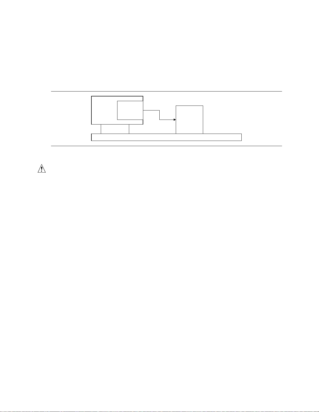
Wake on LAN Technology
The optional Wake on LAN technology connector can be used with PCI bus network adapters that
have a remote wake up connector, as shown in Figure 2. Network adapters that are PCI 2.2
compliant assert the wakeup signal through the PCI bus signal PME# (pin A19 on the PCI bus
connectors). The optional onboard LAN subsystem also supports remote wakeup using the PME#
signal.
Motherboard
PCI Slot
Wake on
LAN
technology
connector
Network
Interface
Card Remote
Wake up
connector
Figure 2. Using the Wake on LAN Technology Connector
CAUTION
For Wake on LAN technology, the 5-V standby line for the power supply must be capable of
delivering +5 V
±
5% at 720 mA. Failure to provide adequate standby current when implementing
Wake on LAN technology can damage the power supply.
Motherboard Features
19
Instantly Available Technology
Instantly Available technology enables the board to enter the ACPI S3 (Suspend-to-RAM) sleep
state. While in the S3 sleep state, the computer will appear to be off. When signaled by a wake up
device or event, the system quickly returns to its last known wake state.
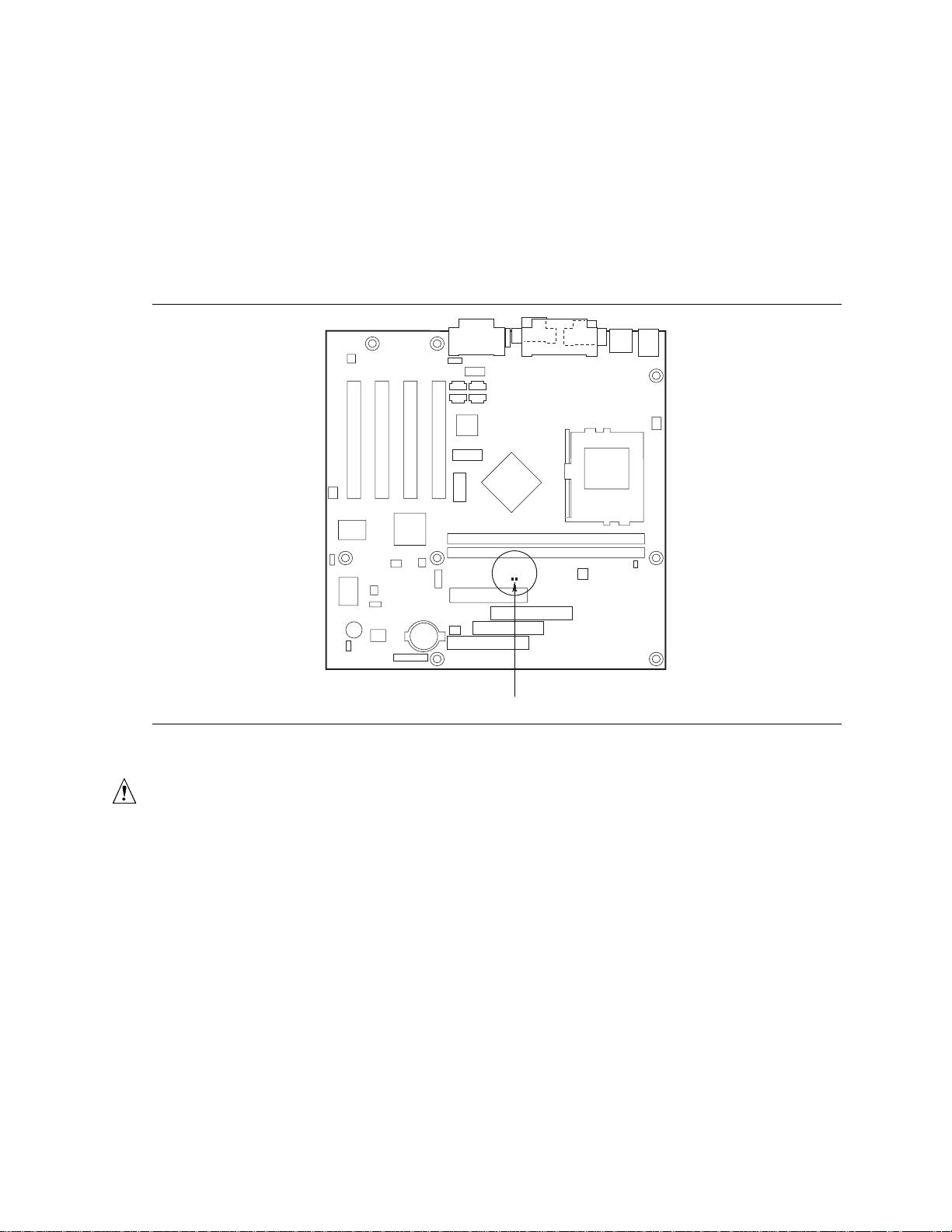
The optional standby power indicator (located between the DIMM sockets and power connector)
provides an indication that power is still present to the DIMMs and PCI bus connectors, even when
the computer appears to be off. Figure 3 shows the location of the standby power LED.
OM07804
DS8E1
Standby Power Indicator
Figure 3. Location of Standby Power Indicator LED
CAUTION
For Instantly Available technology, the 5-V standby line for the power supply must be capable of
delivering +5 V
±
5 % at 720 mA. Failure to provide adequate standby current when using this
feature can damage the power supply.

CA810 Motherboard Product Guide
20
Resume on Ring
The operation of Resume on Ring can be summarized as follows:
•Resumes operation from either the APM sleep mode or the ACPI S1 state
•Requires only one call to access the computer
•Detects incoming call similarly for external and internal modems; does not use the Wake on
Ring connector
•Requires modem interrupt be unmasked for correct operation
Battery
A battery on the motherboard keeps the clock and the values in CMOS RAM current when your
computer is turned off. See Chapter 2 for instructions on how to replace the battery.
Table of contents
Other Seanix Motherboard manuals


