Sears Kenmore Elite 233.51353 Installation guide

Use & Care / Installation Manual
Manual de Uso y Cuidado / Instalación
English / Español
Model/Modelo 233.51353
Kenmore Elite®
Range Hood
Campana de cocina
P/N 99045656-002A
Sears Brands Management Corporation,
Hoffman Estates, IL 60179 USA
www.kenmore.com
TM
®

2
READ AND SAVE THESE INSTRUCTIONS
TABLE OF CONTENTS
SECTION ................................................................... PAGE
Warranty....................................................................................... 2
Safety Instructions ....................................................................... 3
Operation...................................................................................... 4
Cleaning ........................................................................................ 4
Parts Included With Hood ......................................................... 5
Parts Not Included With Hood ................................................. 5
Tools Needed ............................................................................... 5
Equivalent Duct Length Chart ................................................... 6
Install Ductwork ..........................................................................7
Prepare The Hood .................................................................. 7-9
Prepare The Hood Location ............................................... 10-14
EZ1 One-Person Installation ........................................ 10-11
Install The Hood (EZ1 Brackets) .......................................12
Standard Installation (without EZ1 Brackets) ................13
Install The Hood (Standard Installation) ........................14
Connect The Wiring...................................................................15
Install The Filters ........................................................................15
Service Parts ...............................................................................16
KENMORE ELITE LIMITED WARRANTY
5. Damage to or failure of this appliance, including discoloration
or surface rust, if it is not correctly operated and maintained
according to all supplied instructions.
6. Damage to or failure of this appliance, including discoloration
or surface rust, resulting from accident, alteration, abuse,
misuse or use for other than its intended purpose.
7. Damage to or failure of this appliance, including discoloration
or surface rust, caused by the use of detergents, cleaners,
chemicals or utensils other than those recommended in
all instructions supplied with the product.
8. Damage to or failure of parts or systems resulting from
unauthorized modifications made to this appliance.
9. Service to an appliance if the model and serial plate is
missing, altered, or cannot easily be determined to have the
appropriate certification logo.
Disclaimer of implied warranties; limitation of remedies
Customer’s sole and exclusive remedy under this limited warranty
shall be product repair or replacement as provided herein. Implied
warranties, including warranties of merchantability or fitness for a
particular purpose, are limited to one year for the range hood
and thirty days for painted or bright metal parts, or the shortest
period allowed by law. Seller shall not be liable for incidental
or consequential damages. Some states and provinces do not
allow the exclusion or limitation of incidental or consequential
damages, or limitation on the duration of implied warranties
of merchantability or fitness, so these exclusions or limitations
may not apply to you.
This warranty applies only while this appliance is used in the
United States.
This warranty gives you specific legal rights, and you may also
have other rights which vary from state to state.
Sears Brands Management Corporation,
Hoffman Estates, IL 60179
WITH PROOF OF SALE, the following warranty coverage applies
when this appliance is correctly installed, operated and
maintained according to all supplied instructions.
FOR ONE YEAR from the date of sale this appliance is warranted
against defects in material or workmanship. A defective appliance
will receive free repair or replacement at option of seller. This
ONE YEAR coverage does not apply to the finish of any painted
or bright metal part.
FOR THIRTY DAYS from the date of sale, any painted or bright
metal part of this product will be replaced free of charge if its
finish is defective in material or workmanship.
For warranty coverage details to obtain free repair or replacement,
visit the web page: www.kenmore.com/warranty
All warranty coverage is void if this product is ever used for
other than private household purposes.
This warranty covers ONLY defects in material and workmanship,
and will NOT pay for:
1. Expendableitemsthatcanwearoutfromnormaluse,includingbut
not limited to filters, belts, bags or screw-in base light bulbs.
2. A service technician to clean or maintain this appliance, or to
instruct the user in correct appliance installation, operation
and maintenance.
3. Service calls to correct appliance installation not performed
by Sears authorized service agents, or to repair problems
with house fuses, circuit breakers, house wiring, and plumbing
or gas supply systems resulting from such installation.
4. Damage to or failure of this appliance resulting from
installation not performed by Sears authorized service agents,
including installation that was not in accord with electrical,
gas or plumbing codes.
KENMORE ELITE LIMITED WARRANTY

3
WARNING
TO REDUCE THE RISK OF FIRE, ELECTRIC SHOCK, OR
INJURY TO PERSONS, OBSERVE THE FOLLOWING:
1. Use this unit only in the manner intended by the
manufacturer. If you have questions, contact the
manufacturer at the address listed in the warranty.
2. Before servicing or cleaning unit, switch power offat
service panel and lock the service disconnecting means
to prevent power from being switched on accidentally.
When the service disconnecting means cannot be locked,
securely fasten a prominent warning device, such as a tag,
to the service panel.
3. Installation work and electrical wiring must be done by a
qualified person(s) in accordance with all applicable codes
and standards, including fire-rated codes and standards.
4. Sufficient air is needed for proper combustion and
exhausting of gases through the flue (chimney) of fuel
burning equipment to prevent backdrafting. Follow the
heating equipment manufacturer’s guideline and safety
standards such as those published by the National Fire
Protection Association (NFPA), and the American Society
for Heating, Refrigeration and Air Conditioning Engineers
(ASHRAE), and the local code authorities.
5. When cutting or drilling into wall or ceiling, do not damage
electrical wiring and other hidden utilities.
6. To reduce the risk of fire or electric shock, do not use this
range hood with an additional speed control device.
7. Ducted fans must always be vented to the outdoors.
8. To reduce the risk of fire, use only metal ductwork.
9. This unit must be grounded.
TO REDUCE THE RISK OF A RANGE TOP GREASE FIRE:
1. Never leave surface units unattended at high settings.
Boilovers cause smoking and greasy spillovers that may
ignite. Heat oils slowly on low or medium settings.
2. Always turn hood ON when cooking at high heat or when
cooking flaming foods.
3. Clean ventilating fans frequently. Grease should not be
allowed to accumulate on fan or filter.
4. Use proper pan size. Always use cookware appropriate
for the size of the surface element.
WARNING
TO REDUCE THE RISK OF INJURY TO PERSONS IN THE
EVENT OF A RANGE TOP GREASE FIRE, OBSERVE THE
FOLLOWING:*
1. SMOTHER FLAMES with a close-fitting lid, cookie sheet,
or metal tray, then turn offthe burner. BE CAREFUL TO
PREVENT BURNS. If the flames do not go out immediately,
EVACUATE AND CALL THE FIRE DEPARTMENT.
2. NEVER PICK UP A FLAMING PAN - You may be burned.
3. DO NOT USE WATER, including wet dishcloths or towels
- a violent steam explosion will result.
4. Use an extinguisher ONLY if:
A. You know you have a Class ABC extinguisher and you
already know how to operate it.
B. The fire is small and contained in the area where it
started.
C. The fire department is being called.
D. You can fight the fire with your back to an exit.
* Based on “Kitchen Fire safety Tips” published by NFPA.
CAUTION
1. For general ventilating use only. Do not use to exhaust
hazardous or explosive materials and vapors.
2. To avoid motor bearing damage and noisy and/or
unbalanced impellers, keep drywall spray, construction
dust, etc. offpower unit.
3. For best capture of cooking impurities, your range hood
should be mounted so that the top of the hood is 18-30”
above the cooking surface.
4. Use only with range hood cord-connection kits that have
been investigated and found acceptable for use with this
model range hood.
5. Please read specification label on product for further
information and requirements.
SAFETY INSTRUCTIONS
!
NOTE
If hood is to be installed Non-Ducted:
Purchase non-ducted filters and attach them to the hybrid
filters.
!
INTENDED FOR DOMESTIC COOKING ONLY.
!
“Non-ducted Filters” available by calling
1-844-553-6667

4
WARNING: To reduce the risk of electric shock,
disconnect from power supply before cleaning.
Hybrid filters
Clean frequently using hot water and a mild
detergent or in your dishwasher. The hybrid filters should
be washed approximately every month
depending on the amount of usage. Wash more often if
your cooking style generates greater grease - like frying
foods or wok cooking.
Non-ducted recirculation filters
(available separately - see page 5)
The non-ducted recirculation filters should be changed
every 3 to 6 months. Replace more often if your
cooking style generates extra grease, such as
frying and wok cooking. Refer to installation
instructions included with non-ducted recirculation filters.
Stainless steel hood surfaces
Do:
• Regularly wash with clean cloth or rag soaked with
warm water and mild soap or liquid dish detergent.
• Always clean in the direction of original polish lines.
• Always rinse well with clear water (2 or 3 times) after
cleaning. Wipe dry completely.
• You may also use a specialized household stainless
steel cleaner.
Don’t:
• Use any steel or stainless steel wool or any other
scrapers to remove stubborn dirt.
• Use any harsh or abrasive cleansers.
• Allow dirt to accumulate.
• Let plaster dust or any other construction residues
reach the hood. During construction/renovation, cover
the range hood to make sure no dust sticks to the
stainless steel surface.
Avoid when choosing a detergent:
• Any cleaners that contain bleach will attack stainless
steel.
• Any products containing: chloride, fluoride, iodide,
bromide will deteriorate surfaces rapidly.
• Any combustible products used for cleaning such
as acetone, alcohol, ether, benzol, etc., are highly
explosive and should never be used close to a range.
Blower assembly
The center of the fan wheels should be cleaned frequently.
Use a clean cloth soaked with warm detergent solution.
The motors are permanently lubricated and never need
oiling. If the motor bearings make excessive or unusual
noise, replace the motor with the exact service motor. The
fan wheel should also be replaced.
CLEANING
Fan
This rocker switch (on the left) controls the fan. See below:
Light
This rocker switch (on the right) controls the light. See below:
OPERATION
FAN
SWITCH LIGHT
SWITCH
Turns fan OFF.
ITurns fan on to LOW speed.
II Turns fan on to HIGH speed.
Turns light OFF.
ITurns light ON.

5
PARTS INCLUDED WITH HOOD
TOOLS NEEDED FOR HOOD INSTALLATION
Hybrid Grease Filters
(2 per hood)
Parts Bag
(4 no. 8-18 x 1/2" metal screws,
6 no. 8 x 5/8" round head wood screws,
6 no. 8 x 1/2" countersunk wood screws)
Screwdriver
(Flat & Phillips no. 2)
Nutdriver
11/32"
Tape
Measure
Drill
(with 1/8" and
7/64" drill bits,
and 1½" hole saw)
Sabre Saw
Keyhole
Saw
-or-
Metal Foil
Duct Tape
Wire
Stripper
PARTS NOT INCLUDED WITH HOOD
OPTIONAL PARTS (purchase separately)
Non-Ducted Recirculation Filters
(Non-ducted hoods only)
(2 per hood)
Part No. S97020466
7-inch Round Damper
(For use with 7-inch Round Duct)
Part No. 59183
3¼” x 10”
Damper / Duct Connector
C
L
AB
Apoyar esteborde contra la pared de atrásPlace this edge against back wall
VERTICAL EXHAUST
S
A
A
V
RTICAL EX
=3¼” x 10”
=3¼” x 14”
RECTANGULARDUCTING7”ROUND DUCTING OR
Usethis template for marking; do not attempt to cut out the ducting hole through it.
NOTE:Thesecutouts are clearance holes; they do not need to be the exact size of ducting.
=3¼ po x 10 po
=3¼ po x 14 po
CONDUIT RECTANGULAIRECONDUITRO ND DE 7 PO OU
=3¼ pulg. x 10 pulg.
=3¼ pulg. x 14 pulg.
CONDUCTORECTANGULARCONDUCTOREDONDO
DE 7 PULG.O
Appuyer ce bord au mur arrière
Utiliserce gabarit pour marquer vos repères; ne pas tenter de découper
letrou pour le conduit à travers le gabarit.
NOTE: Les découpes incluent le jeu nécessaire à l’installation; elles ne doivent pas
être du format exact des conduits.
Useesta plantilla para crear marcados; no trate de cortar el
agujerodel conducto a través de la plantilla.
NOTA:Tobe translated in Spanish.
MARKWHERE INDICATED
FOR THE APPROPRIATESIZE DUCT OPENING
MARQUERLES REPÈRES AU X ENDROITSINDIQUÉS SELON
LE FORMATDE CONDUIT UTILISÉ
TITLE TO BE TRANSLATEDIN SPAN ISH
Electricalaccess hole center
A=single blower hood
B=double blower hood
Centredu trou pour fil
d’alimentationélectrique
A=hotte ventilateur simple
B=hotte ventilateur double
Tobe translated in Spanish
Electricalaccess hole center
A=single blower hood
B=double blower hood
4¼”
10½”
14½”
8”
7½”
CC
CBendtemplate along graduated
scalewhen installing to framed
cabinet.
Pourune installation sous une
armoireà fond en retrait, utiliser les
lignespour mesurer l’épaisseur du
décalagecausé par le mur de
l’armoireet plier le gabarit en
conséquence.
Tobe translated in Spanish.
EZ-1 One person Installation Kit
(including template for
ducting, printed both sides,
and installation brackets)
7” Round Duct Connector
Long Nose
Pliers
HR0064
Sheet Metal
Shears
Pencil
“Parts Not Included With Hood” available by calling
1-844-553-6667

6
EQUIVALENT DUCT LENGTH CHART
Straight Duct
3¼-in. x 10-in. x 2-ft. long
Equivalent length
2 ft.
7-in. Round Elbow
Equivalent length
8 ft.
3¼-in. x 10-in.
Right-angle Elbow
Equivalent length
8.5 ft.
3¼-in. x 10-in.
Right-angle Flat Elbow
Equivalent length
24 ft.
3¼-in. x 10-in.
Right-angle
Short Eave
Elbow
Equivalent length
15 ft.
3¼-in. x 10-in.
Right-angle
Long Eave
Elbow
Equivalent length
15 ft.
3¼-in. x 10-in.
Wall Cap
Equivalent
length
45 ft.
(7-ft. w/o
damper)
Roof Cap
(accepts 7-in. round
or 3¼-in. x 10-in. duct)
Equivalent length
30 ft. (7-ft. w/o damper)
Kenmore range hoods are designed to perform efficiently when attached to long runs of duct. As a point of reference, this
hood will function at approximately 80% of its rated air flow when 30 equivalent feet of 7" round ductwork is attached.
Use this chart to calculate the equivalent duct length of your system.
Straight Duct
7-in. round x 2-ft. long
Equivalent length
2 ft.
3¼-in. x 10-in. to
7-in. Round
Transition
Equivalent length
5.5 ft.
7-in. Round
Wall Cap
Equivalent length
34 ft.
(6-ft. w/o damper)
“Ducting Accessories” available by calling
1-844-553-6667

7
SOFFIT
18" MIN - 30" MAX
ABOVE COOKING SURFACE
CABINET
3¼" X10" DUCT
(FOR HORIZONTAL DISCHARGE)
WALL CAP
ROOF CAP 3¼" X10" OR
7" ROUND DUCT
(FOR VERTICAL
DISCHARGE)
HOUSE WIRING
(TOP OR BACK OF HOOD)
HOOD
1. Determine whether hood will discharge vertically (3¼” x 10”
or 7” Round) or horizontally (3¼” x 10” only).
2. Run ductwork between the hood location and a roof cap
or wall cap.
3. Choose a straight, short duct run to allow the hood to
perform most efficiently. Long duct runs, elbows and
transitions will reduce the performance of the hood. Use
as few of them as possible. When possible, use at least
2 foot straight runs before any turns. Larger ductwork may
be required for best performance with longer duct runs.
4. Install wall cap or roof cap (sold separately). Connect
metal ductwork to cap and work back towards the hood
location. Use 2” metal foil duct tape to seal the joints
between ductwork sections.
INSTALL DUCTWORK (DUCTED INSTALLATION ONLY)
NOTE: Distances over 30” are at the installer and user
discretion.
1. If present, remove all protective polyfilm from the hood
and/or parts. Using the finger cup, remove the Hybrid
Filters from the hood by pushing down and tilting filters
out.
PREPARE THE HOOD
B
C
2. Remove both fillers by removing the 3 screws holding each
one of them. Slide each one towards the center of the
hood and tilt it up to remove it completely. Set the fillers
and screws aside.
c
d

8
3. Remove the screw holding the damper assembly,
remove the tape strip and and put the damper
assembly aside. Save this screws, it will be used later to
hold the blower cover plate.
4. Remove both tape strips holding the 7” round duct plate,
and put the duct plate aside.
5. Remove the parts bag taped in the lower left corner of
the hood.
RECIRCULATION
COVER PLATE
SCREWS
ELECTRICAL
POWER
CABLE
KNOCKOUT
7” ROUND
DUCT PLATE
1 SCREW
8. Remove Electrical Power Cable Knockout from top
(vertical exhaust) or back (horizontal exhaust) of
hood. For knockout removed from back of hood,
install an appropriate strain relief, 1/2” diameter
(not included). For knockout removed from top of hood,
the strain relief will be installed later.
NON-DUCTED INSTALLATIONS ONLY
9. Remove 3 screws retaining the recirculation cover plate to the hood. Discard this plate with its screws. Peel offand
discard the membrane (shaded part in illustration below) covering the recirculation grille, ensuring the openings are
totally cleared.
TAPE
TAPE
TAPE
DAMPER
ASSEMBLY
PARTS BAG
6. Using a 11/32” nut driver, remove the lock nut retaining
the flange of the right blower cover plate (shaded part on
illustration beside) to the inner back of hood (see inset).
Remove the right cover plate remaining retaining screws
(6 screws), then set the blower cover along with its screws
and nut aside.
NOTE: Sightly lift up the cover plate before sliding it towards
the left to remove it.
12
3
45
6
7
BACK OF HOOD
LOCK NUT
SCREW
REMOVED IN
STEP 3
EZ1
BRACKETS
7. Remove the EZ1 brackets from inside the hood by cutting
offthe tie wrap. Discard the tie wrap.

9
DUCTED INSTALLATIONS ONLY
10.Remove 3¼” x 10” vertical, 3¼” x 10” horizontal (both are the rectangular central knockout plates, see hatched
areas), or 7-inch round knockout plate as appropriate for your ducting method (see FIGURES 1 A and 1 B).
7” ROUND
DUCT
PLATE
3¼” X10”
DAMPER
ASSEMBLY
SCREWS
FIGURE 3 A
TOP/BACK
EDGE OF
HOOD
DAMPER
FLAP
PIVOT
FIGURE 3 B
3¼” X10”
DAMPER
ASSEMBLY
BACK OF
HOOD
DAMPER
FLAP
PIVOT
SCREWS
7” ROUND
KNOCKOUT PLATE
(ALSO REMOVE VERTICAL
KNOCKOUT PLATE)
3¼” X10”
VERTICAL
KNOCKOUT
PLATE 3¼” X10”
HORIZONTAL
KNOCKOUT
PLATE
FIGURE 1 A FIGURE 1 B
TIP: Insert a small length of duct over the 3¼” x 10” damper assembly (for rectangular ducting) or 7” round (for
round ducting) and seal the joint using aluminum foil duct tape to ease connection with the house ductwork.
SCREWS
FIGURE 2
11. Using the screws located on top of the hood (FIGURE 2), attach
the 3¼” x 10” Damper Assembly on top OR back of hood
(if using 3¼” x 10” duct; shaded par in FIGURE 3 A below)
or 7” Round Duct Plate (if using 7-inch round duct, FIGURE
4) over the knockout opening. When installed, the 3¼” x
10” damper assembly must open as shown in FIGURE 3 B.
NOTE: To accommodate off-center ductwork,
the 7” round duct plate can be installed up to
1/2” on either side of the hood center.
FIGURE 4
SCREWS

10
PREPARE THE HOOD LOCATION
NOTE: Before starting installation, read all the steps of
these instructions.
Use the illustration beside to identify your kitchen cabinet
type.
EZ1 One-person installation system
This manual covers 2 kinds of installation: the standard
(without EZ1 brackets) and the EZ1 one-person installation
system (using included template and brackets). For the
standard installation, go to page 14.
FRAMED CABINET FRAMELESS CABINET
CABINET FRONT
C
L
AB
Apoyar este borde contra la pared de atrásPlace this edge against back wall
VERTICAL EXHAUST
A
S
A
A
V
RTICAL EX
= 3¼” x 10”
= 3¼” x 14”
RECTANGULAR DUCTING7” ROUND DUCTING OR
Use this template formarking; do not attempt to cut out the ducting hole through it.
NOTE:These cutouts are clearance holes; they do not need tobe the exact size of ducting.
= 3¼ po x 10po
= 3¼ po x 14 po
CONDUIT RECTANGULAIRECONDUIT ROND DE 7 PO OU
= 3¼ pulg.x 10 pulg.
= 3¼ pulg.x 14 pulg.
CONDUCTO RECTANGULARCONDUCTO REDONDO
DE 7 PULG.O
Appuyer ce bord au mur arrière
Utiliser ce gabarit pour marquer vosrepères; ne pas tenter de découper
le trou pour le conduit à traversle gabarit.
NOTE :Les découpes incluent le jeu nécessaire à l’installation; elles ne doivent pas
êtredu format exact des conduits.
Use esta plantilla para crearmarcados; no trate de cortar el
agujero del conductoa través de la plantilla.
NOTA:Tobe translated in Spanish.
MARK WHERE INDICATED
FOR THE APPROPRIATE SIZE DUCT OPENING
MARQUER LES REPÈRES AUX ENDROITS INDIQUÉS SELON
LE FORMAT DE CONDUIT UTILISÉ
TITLE TO BE TRANSLATED IN SPANISH
Electrical access hole center
A= single blowerhood
B= double blowerhood
Centre du troupour fil
d’alimentation électrique
A= hotteventilateur simple
B= hotteventilateur double
Tobe translated in Spanish
Electrical access hole center
A= single blowerhood
B= double blowerhood
4¼”
10½”
14½”
8”
7½”
CC
CBend template along graduated
scale when installing to framed
cabinet.
Pour une installation sous une
armoire à fonden retrait, utiliser les
lignes pour mesurer l’épaisseur du
décalage causé par le mur de
l’armoire et plier le gabariten
conséquence.
Tobe translated in Spanish.
P
C
CABINET FRONT
C
L
AB
VERTICAL EXHAUST
A
S
A
A
V
RTICAL EX
= 3¼” x 10”
= 3¼” x 14”
RECTANGULAR DUCTING7” ROUND DUCTING OR
Use this template formarking; do not attempt to cut out the ducting hole through it.
NOTE:These cutouts are clearance holes; they do not need tobe the exact size of ducting.
= 3¼ po x 10po
= 3¼ po x 14 po
CONDUIT RECTANGULAIRECONDUIT ROND DE 7 PO OU
= 3¼ pulg.x 10 pulg.
= 3¼ pulg.x 14 pulg.
CONDUCTO RECTANGULARCONDUCTO REDONDO
DE 7 PULG.O
Utiliser ce gabarit pour marquer vosrepères; ne pas tenter de découper
le trou pour le conduit à traversle gabarit.
NOTE :Les découpes incluent le jeu nécessaire à l’installation; elles ne doivent pas
êtredu format exact des conduits.
Use esta plantilla para crearmarcados; no trate de cortar el
agujero del conductoa través de la plantilla.
NOTA:Tobe translated in Spanish.
MARK WHERE INDICATED
FOR THE APPROPRIATE SIZE DUCT OPENING
MARQUER LES REPÈRES AUX ENDROITS INDIQUÉS SELON
LE FORMAT DE CONDUIT UTILISÉ
TITLE TO BE TRANSLATED IN SPANISH
Electrical access hole center
A= single blowerhood
B= double blowerhood
Centre du troupour fil
d’alimentation électrique
A= hotteventilateur simple
B= hotteventilateur double
Tobe translated in Spanish
Electrical access hole center
A= single blowerhood
B= double blowerhood
4¼”
10½”
14½”
8”
7½”
CC
CBend template along graduated
scale when installing to framed
cabinet.
Pour une installation sous une
armoire à fonden retrait, utiliser les
lignes pour mesurer l’épaisseur du
décalage causé par le mur de
l’armoire et plier le gabariten
conséquence.
Tobe translated in Spanish.
ELECTRICAL
ACCESS HOLE
LOCATION (B)
(IN CABINET BOTTOM)
CENTER LINE
FOLD TEMPLATE ALONG GRADUATED
SCALE WHEN INSTALLING TO FRAMED
CABINET.
B
VERTICAL
EXHAUST DUCTING
EZ1 installation is designed for use with kitchen cabinets that have the same width designation as the range hood width.
If the cabinet is greater than 1/2” wider than the range hood width, please use the standard installation method.
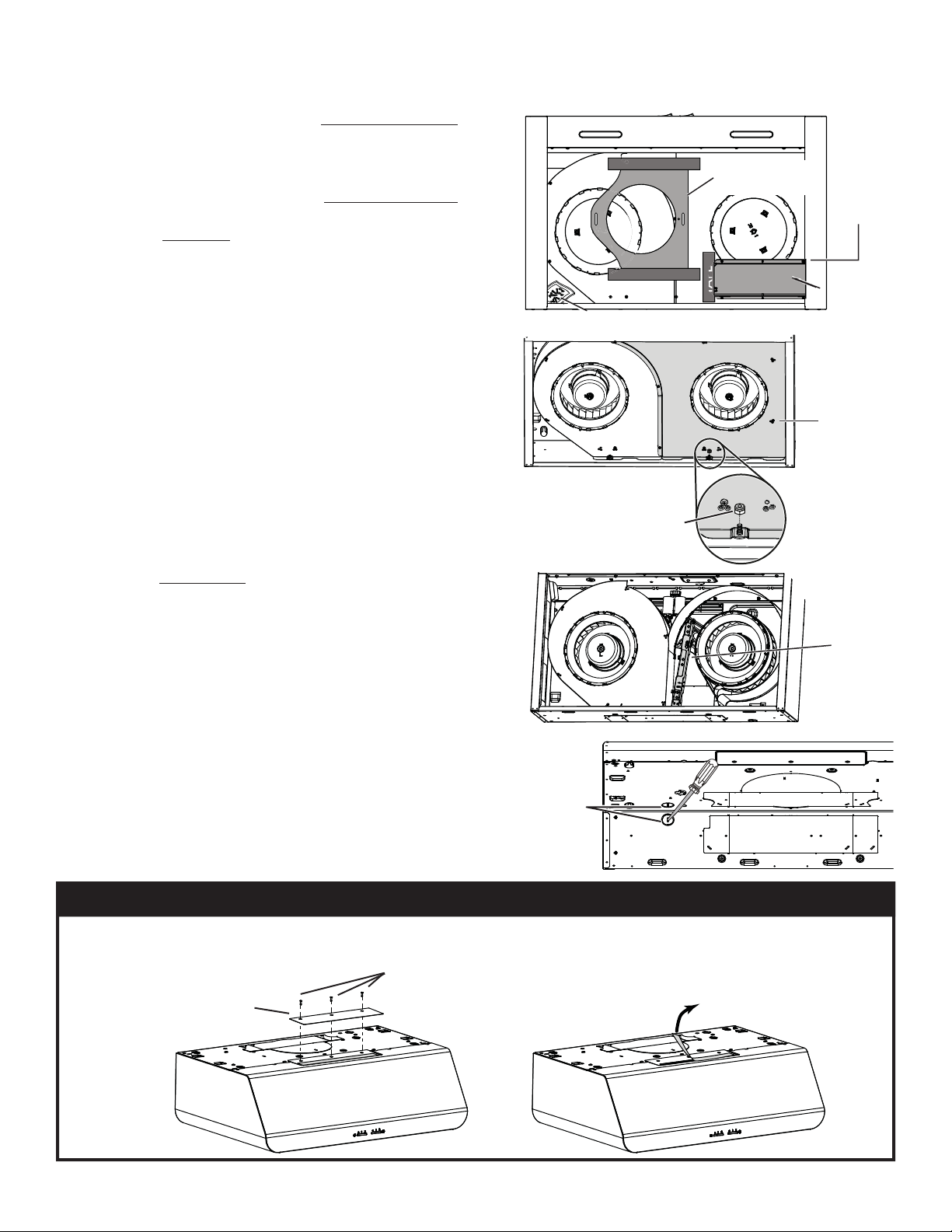
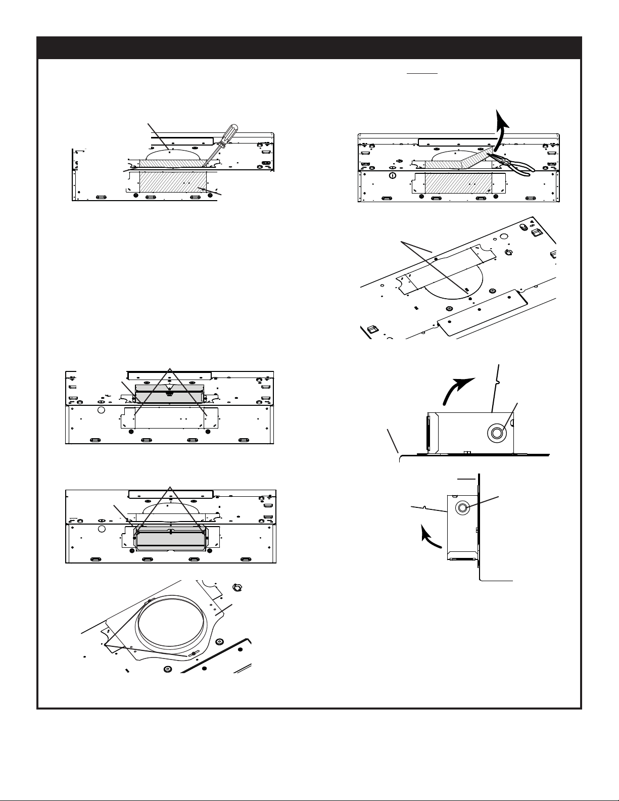
1. Use the proper template for vertical OR horizontal
disharge (included) for placement of ductwork and
electrical cutout in cabinet or wall. For a non-ducted
installation, DO NOT cut a duct access hole, only cut the
hole for electrical wiring. If replacing a hood and plan to
use the existing duct and electrical, steps 2 to 5 may not
be necessary. If so, skip to step 6.
2. Measure and mark the hood center line on cabinet bottom.
3. Align the center line on template with the hood center
line marked on the bottom of the cabinet, placing the
edge (where indicated) of the template against back
wall. When using with framed cabinet for vertical exhaust
installation, fold over rear edge of template equal to the
depth of the cabinet frame at the wall (use graduations
on template, Clocations on template). Tape the template
in place.
NOTE: When facing the installation, Aand B(on
template) must be at right.
ELECTRICAL
ACCESS HOLE
LOCATION (B)
(IN WALL)
CENTER LINE
C
L
AB
Place this edge against
cabinet bottom.
Appuyer ce bord contre le bas
de l’armoire.
Apoyar este borde contra
la base del armario.
HORIZONTAL EXHAUST
T
T
= 3¼ pulg.x 10 pulg.
= 3¼ pulg.x 14 pulg.
CONDUCTO RECTANGULAR
= 3¼”x 10”
= 3¼”x 14”
RECTANGULAR DUCTING
= 3¼ po x 10po
= 3¼ po x 14po
CONDUIT RECTANGULAIRE
MARK WHERE INDICATED
FOR THE APPROPRIATE SIZE DUCT OPENING
MARQUER LES REPÈRES AUX ENDROITS INDIQUÉS SELON
LE FORMAT DE CONDUIT UTILISÉ
TITLE TO BE TRANSLATED IN SPANISH
Use this templatefor marking; do not attempt to cut out the ducting hole through it.
NOTE:These cutouts are clearance holes; theydo not need to be the exact size of ducting.
Utiliser ce gabarit pour marquervos repères; ne pas tenter de découper
le trou pour le conduit à traversle gabarit.
NOTE: Les découpes incluent le jeu nécessaire à l’installation;elles ne doivent pas
être du formatexact des conduits.
Use esta plantilla para crearmarcados; no trate de cortar el
agujerodel conducto a través de la plantilla.
NOTA:Tobe translated in Spanish.
Electrical access hole center
A= single blowerhood
B= double blowerhood
Centredu trou pour fil
d’alimentation électrique
A= hotteventilateur simple
B= hotteventilateur double
Tobe translated in Spanish
Electrical access hole center
A= single blowerhood
B= double blowerhood B
ess hole center
wer hood
wer hood
HORIZONTAL
EXHAUST DUCTING
4. Drill a 1/8” dia. pilot hole for house wiring, at Blocation
on template.
5. Use a sharp pencil or 1/8” drill bit to mark the locations
for the appropriate duct access holes (16 locations for 7”
round duct, or 4 corner locations for rectangular duct).
Remove the template.
6. Draw the border for the exhaust ducting by linking its
marks (16 for round duct and 4 for rectangular duct), then
cut the opening in the cabinet bottom (vertical exhaust)
or in the wall (horizontal exhaust). Drill the house wiring
hole by using a 1½” hole saw centered with the pilot hole
previously made in 4.

11
FRAMED CABINET
7/64”
XY
Z
Refer to the marking on the brackets to determine
the correct installation side and orientation.
Mate the corresponding bracket to the cabinet side
frame, while placing rear end of bracket against the
wall. Use a pencil to mark 3 holes (there are 6 holes
but only 3 are necessary).
Remove the bracket. Using a 7/64” drill bit, drill 3 holes
where marked.
7. Install the proper installation brackets according to the
type of cabinet (framed or frameless). See below.
Assemble the bracket to the side frame using a
Phillips screwdriver and 3 provided no. 8 x 5/8” wood
screws. Repeat for the other side frame.
[ \
7/64”
X
3 X
YZ
FRAMELESS CABINET
Refer to the marking on the brackets to determine
the correct installation side and orientation.
Align the corresponding bracket to the cabinet side,
while placing rear end of bracket against the wall.
Draw a line on the outer edge of the bracket (as shown).
Slide the bracket towards the center of cabinet and
align the outside edge of the bracket with the marked
line, keeping the rear end edge leaning on the wall.
Use a pencil to mark 3 holes.
Remove the bracket. Using a 7/64” drill bit,
drill 3 holes where marked.
Assemble the bracket to the cabinet bottom using
a Phillips screwdriver and 3 provided countersunk
wood screws. Repeat for the other cabinet side.

12
A
C
B
D
HORIZONTAL EXHAUST INSTALLATION ONLY
A
B
Install the hood (EZ1 brackets)
NOTE: The following procedure applies to both
framed or frameless cabinet installations.
1. Run house power cable between service panel and
hood location.
2. There are 2 pairs of recessed holes on each side of the
top of the hood (on rear: Aand B, on front Cand Don
illustration beside); these holes allow the range hood to
hang on the brackets (previously installed).
3. Temporarily hang the hood on the brackets using its
2 recessed REAR HOLES (Aand B). While holding the
hood, run the house power cable into the hood through
the strain relief previously installed in step 8 on page 8.
4. Unhook the rear holes from the brackets and hang the
hood using its 2 recessed FRONT HOLES (Cand D).
While holding the hood, go to step 6.
VERTICAL EXHAUST INSTALLATION ONLY
5. Hang the hood on the brackets using the 2 recessed
FRONT HOLES (Cand D). While holding the hood,
tighten an appropriate strain relief, 1/2” diameter (not
included) to the power cable, then insert the strain relief
in the knockout hole.
DUCTED INSTALLATIONS ONLY
6. Connect the ductwork to the hood and use metal foil duct tape to make joints secure and air-tight. Make sure the
damper assembly (or round duct plate) enters the ductwork and that the damper opens and closes freely.
FRAMED CABINET FRAMELESS CABINET
WOOD
SCREWS
METAL
SCREWS
7. For framed cabinet, secure the hood to the EZ1 brackets
using 4 no. 8-18 x 1/2” metal screws (screws included in
parts bag). Insert 2 screws per side, in the slots
(as shown in inset on illustration beside).
8. For frameless cabinet, secure the hood to the cabinet
using 4 no. 8 x 5/8” round head wood screws (screws
included in parts bag). Insert 2 screws per side, in the
slots (as shown in inset on illustration beside).
9. Attach power cable to the hood using the strain relief.

13
3¼” x 10”
VERTICAL DUCTING
3¼” x 10”
HORIZONTAL DUCTING
7” ROUND
VERTICAL DUCTING
1. Use these diagrams for proper placement of ductwork
and electrical cutout in cabinet or wall.
For a non-ducted installation, DO NOT cut a duct access
hole, only cut the hole for electrical wiring.
Standard Installation (without EZ1 brackets)
VERTICAL DUCT
ACCESS HOLE
5¼"
5¼"
CENTER LINE
ELECTRICALACCESS
HOLE (IN CABINET BOTTOM)
WOOD SHIMS
(RECESSED-BOTTOM
CABINETS ONLY)CABINET FRONT
3/4"
1Ǫ"
1½"
9¾"
12Ǭ"
47/16"
CABINET
BOTTOM
12Ǭ"
REAR HOOD MOUNTING SCREWS (2)
CABINET
BOTTOM
CABINET FRONT
HORIZONTAL DUCT
ACCESS HOLE
REAR HOOD
MOUNTING
SCREWS (2)
ELECTRICAL
ACCESS HOLE
(IN WALL)
3Ǭ"
CENTER
LINE
WOOD SHIMS
(RECESSED-BOTTOM
CABINETS ONLY)13/16"
3/16"
5¼" 5¼"
12Ǭ"12Ǭ"
9¾"
4¹¹/16"8" DIA.
HOLE
7-IN. ROUND
DUCT
ACCESS
HOLE
7-IN. ROUND
DUCT
ACCESS
HOLE 1½"
Ǫ
9¾"
CENTER LINE
ELECTRICALACCESS
HOLE (IN CABINET BOTTOM)
12Ǭ"12Ǭ"
REAR HOOD MOUNTING SCREWS (2)
WOOD SHIMS
(RECESSED-BOTTOM
CABINETS ONLY)
2. Install part-way two (2) ROUND HEAD no. 8 x 5/8”
mounting screws into shims/cabinet, according to the
proper diagram above, the other 2 ROUND HEAD
no. 8 x 5/8” mounting screws will be used later. (Mounting
screws are included in parts bag, but wood shims and
shim mounting screws are not included).

14
Install the Hood (Standard Installation)
1. Run house power cable between service panel and hood
location. For hood with power cable access located on
back of hood, run the house power cable into the hood
through the strain relief previously installed in step 8 on
page 8. For hood with power cable access located on
top, tighten the strain relief to the power cable before
inserting the strain relief in the knockout hole.
2. Hang hood from (2) mounting screws previously installed.
Slide hood back towards wall until mounting screw heads
are engaged in narrow end of keyhole slots in top of hood.
Tighten screws securely and maintain a hold on the hood
until completing step 3.
DUCTED INSTALLATIONS ONLY
4. Connect the ductwork to the hood and use metal foil duct tape to make joints secure and air-tight. Make sure
the damper assembly (or round duct plate) enters the ductwork and that the damper opens and closes freely.
NOTE: Two installers are recommended because of the weight of this hood.
BACK OF HOOD
SCREW PREVIOUSLY
TIGHTENED IN STEP 2
3. Secure the hood to the cabinet using 2 no. 8 x 5/8” round
head wood screws (screws included in parts bag). Insert
1 screw per side, in the slots (as shown beside). Attach
power cable to the hood using the strain relief.

15
WARNING: Risk of electric shock. Electrical wiring
must be done by qualified personnel in accordance
with all applicable codes and standards. Before con-
necting wires, switch power offat service panel and
lock service disconnecting means to prevent power
from being switched on accidentally.
1. Connect House Power Cable to range hood wiring: BLACK
to BLACK, WHITE to WHITE and GREEN or bare wire
under GREEN ground screw.
2. Reinstall the blower cover plate (shaded part on illustration
beside) using the lock nut and7screws previously removed
in steps 3 and 6 on page 8. Pay attention to screw 1
location; from back of hood point of view, it must be
located on left side of the lock nut (see inset).
CONNECT THE WIRING
MOTORS
GROUND
WIRE
HOUSE
POWER
CABLE
GROUND
SCREW
Ducted Installation Only:
Re-install grease filters removed in step 1on page 7, under
“Prepare the Hood”.
INSTALL THE FILTERS
c
d
e
12
3
45
6
7
BACK OF HOOD
LOCK NUT
1
3. Reinstall the fillers by following steps as illustrated beside.
“Non-ducted Filters” available by calling
1-844-553-6667
Non-ducted Installation Only:
Purchase two non-ducted filters (see part number in Service
parts list). Attach the non-ducted filters following instructions
packed with the non-ducted filters.

16
SERVICE PARTS
1
2
34
7
5
6
9
KEY NO. PART NO. DESCRIPTION QUANTITY
1 S97020031 RECIRCULATION COVER PLATE, STAINLESS STEEL (INCL. SCREWS)1
2 SR680508 7'' ROUND DUCT PLATE (INCLUDING SCREWS)1
3 S97020534 3¼” X10” DAMPER ASSEMBLY (INCLUDING SCREWS)1
4 S97020412 CAPACITOR 2
5 S97020842 BLOWER ASS'YCW (INCLUDING ITEMS 4 AND 6 AND HARDWARE)1
6 SR99420635 CLIP FOR FANPELLER 1
7 S97020204-002 GREASE FILTER - HYBRID - TYPE C1 (SET OF 2) 1
8 S97020843 BLOWER ASS'YCCW (INCLUDING ITEMS 4 AND 6 AND HARDWARE)1
9 S97020797 AUTOTRANSFORMER (WITH SCREWS)1
10 S97020444 LED MODULE (PAIR)1
11 S97020425 ELONGATED ROCKER SWITCH (GREY)1
12 S97020477 LED DRIVER 1
* S97020772 WIRE HARNESS WITH AUTOTRANSFORMER AND FUSE 1
* S97020360 PARTS BAG INCLUDING: 4 METAL SCREWS NO. 8-18 X1/2”,
6 ROUND HEAD NO. 8 X5/8” WOOD SCREWS,
6 NO. 8 X1/2” COUNTERSUNK SCREWS
1
* S97020466 NON-DUCTED FILTER - TYPE XC(SET OF 2)
(NON-DUCTED INSTALLATION ONLY)1
* S99527587 NON-DUCTED FILTER CLIP KIT (INCLUDES 4 CLIPS)1
* S97020470 EASY INSTALL KIT (INCLUDING HARDWARE)1
Order replacement parts by PART NO. - not by KEY NO.
* Not illustrated
REPLACEMENT PARTS
In order to ensure your unit remains in good working condition, you must use the manufacturer genuine replacement parts only. The
manufacturer genuine replacement parts are specially designed for each unit and are manufactured to comply with all the applicable
certification standards and maintain a high standard of safety. Any third party replacement part used may cause serious damage and
drastically reduce the performance level of your unit, which will result in premature failing. To purchase the genuine replacement parts
listed above, call 1-844-553-6667.
8
6
10
11
12

17
LEA Y CONSERVE ESTAS INSTRUCCIONES
TABLA DE CONTENIDO
SECCIÓN...............................................................PÁGINA
Garantía.......................................................................................17
Instrucciones de seguridad.......................................................18
Operación....................................................................................19
Limpieza .......................................................................................19
Piezas incluidas con la campana............................................19
Piezas no incluidas con la campana .....................................20
Herramientas necesarias..........................................................20
Cuadro de largo equivalentes de conducto..........................21
Instale los conductos................................................................. 22
Prepare la campana ..........................................................22-24
Prepare la ubicación para la campana..........................25-29
Instalación EZ1 por una persona...............................25-26
Instale la campana (Soportes EZ1) ................................27
Instalación normal (Sin soportes EZ1) ...........................28
Instale la campana (Instalación normal) ...................... 29
Conecte el cableado ................................................................30
Instale los filtros .........................................................................30
Piezas de servicio.......................................................................31
GARANTÍA LIMITADA DE KENMORE ELITE
4. Daños en el aparato o fallos causados en él debidos
a una instalación no realizada por técnicos de servicio
autorizados de Sears, incluyendo en ello los casos de
instalación no conformes con los códigos de electricidad,
gas y plomería.
5. Daños en el aparato o fallos causados en él — entre
ellos la descoloración o la oxidación superficial— si no
se usa correctamente o no se le da mantenimiento de
acuerdo con todas las instrucciones dadas.
6. Daños en el aparato o fallos causados en él — entre el-
los la descoloración o la oxidación superficial— debidos
a un accidente, alteración, abuso, mal uso o uso distinto
al previsto.
7. Daños en el aparato o fallos causados en él — entre el-
los la descoloración o la oxidación superficial— debidos
al uso de detergentes, limpiadores, productos químicos
o utensilios distintos a los recomendados en todas las
instrucciones dadas con el producto.
8.Dañosenpiezas o sistemas del aparatoofalloscausados
en ellos debidos a modificaciones no autorizadas hechas
en el aparato.
9. Gastos de servicio en un aparato cuya placa con el
modelo y número de serie ha desaparecido, ha sido
alterada o no pueda comprobarse fácilmente que lleva
el logo de certificación apropiado.
Denegación de garantías implícitas; limitación de los
recursos
El único recurso de que dispone el cliente conforme a
esta garantía limitada será la reparación o la sustitución
del producto, tal y como aquí se indica. Las garantías
implícitas, tales como las garantías de comerciabilidad o
de idoneidad para un determinado propósito, se limitan
a un año para la campana de cocina y a treinta días
para las piezas pintadas o metálicas brillantes, o al peri-
odo más corto que permita la ley. El vendedor no será re-
sponsable de los daños incidentales o derivados. Algunos
estados y provincias no permiten que se excluyan o lim-
iten los daños incidentales o derivados o que se limite la
duración de las garantías implícitas de comerciabilidad o
idoneidad; en tales casos, estas exclusiones o limitaciones
no se aplican a usted.
Esta garantía sólo se aplica cuando el aparato se usa en
Estados Unidos.
Esta garantía le concede derechos legales específicos,
y usted puede tener también otros derechos que varían
de un estado a otro.
Sears Brands Management Corporation,
Hoffman Estates, Illinois 60179
GARANTÍA LIMITADA DE KENMORE ELITE
La garantía siguiente se aplica, CON UN COMPROBANTE
DE VENTA, cuando este aparato se instala, se utiliza y se
mantiene de acuerdo con todas las instrucciones dadas.
Esteaparatoestá garantizadoDURANTEUNAÑO, apartir
de la fecha de venta, contra los defectos de material
y de mano de obra. Un aparato defectuoso será reparado
osustituido,segúndecidaelvendedor.Elperiododegarantía
de UN AÑO no se aplica al acabado de las piezas
pintadas o de las piezas metálicas brillantes.
Durante un plazo de TREINTA DÍAS a partir de la fecha
de compra, las piezas pintadas o metálicas brillantes de
este producto serán sustituidas sin gastos si su acabado
tiene defectos de material o de mano de obra.
Para mayor información sobre la forma de obtener una
reparación o una sustitución gratuita, sírvase consultar la
página web www.kenmore.com/warranty
La garantía queda anulada si este producto se utiliza
alguna vez con fines distintos al uso doméstico privado.
EstagarantíacubreÚNICAMENTElosdefectosde material
y mano de obra y NO los siguientes casos:
1. Artículos fungibles que pueden desgastarse con el uso
normal, tales como filtros, correas, bolsas o bombillas.
2. Gastos generados por un técnico de servicio para
limpiar o dar mantenimiento a este aparato o para dar
instruccionesalusuariosobrelainstalación,funcionamiento
y mantenimiento correctos del aparato.
3. Solicitudes de servicio para corregir una instalación
del aparato no realizada por técnicos de servicio
autorizadosdeSearsopararepararproblemasdelosfusibles,
disyuntores y cableado domésticos y de los sistemas de
plomería o de alimentación de gas causados por dicha
instalación.

18
INSTRUCCIONES DE SEGURIDAD
!
PREVISTO PARA COCINAR DOMÉSTICO SOLAMENTE.
!
ADVERTENCIA
PARA REDUCIR EL RIESGO DE INCENDIO, CHOQUE
ELÉCTRICO, O LESIÓN A PERSONAS, OBSERVE LO
SIGUIENTE:
1. Utilice esta unidad sólo en la manera prescrita por el
fabricante. Si tiene usted alguna pregunta, comuniqúese
con el fabricante a la dirección o al télefono indicados
en la garantía.
2. Antes de efectuar algún servicio o limpieza, se debe
desconectar la corriente eléctrica en el armario de
circuitos y asegurarlo con llave para evitar que la corriente
sea conectada accidentalmente. Cuando el medio de
desconexión del servicio no puede ser trabado, sujete un
dispositivo de advertencia evidente, tal como una etiqueta,
al panel de servicio.
3. Todo trabajo do instalación y cableado eléctrico debe ser
realizado por personal calificado y de acuerdo con todos
los códigos y normas pertinentes, incluyendo los códigos
y normas relacionados con construcción clasificada para
incendio.
4. Aire suficiente es necesario para facilitar la combustión
adecuada y la salida apropiada de gases por la chimenea
de la unidad y para evitar corrientes de aire invertidas.
Siga las instrucciones y medidas de seguridad del
fabricante del equipo y de las sociedades profesionales de
equipos do calentadores y los reglamentos de seguridad
locales.
5. Al cortar o perforar la pared o el techo, no dañe el
cableado eléctrico y otros servicios públicos ocultos.
6. Para reducir el riesgo de incendio o de descarga eléctrica,
no utilice esta campana con un dispositivo de control de
velocidad adicional.
7. Los ventiladores con conducto deberán siempre tener una
salida hacia el exterior.
8. Para reducir el riesgo de incendio, use sólo conductos de
metal.
9. Esta unidad se debe instalar con conexión a tierra.
PARA REDUCIR EL RIESGO DE UN INCENDIO POR GRASA
EN LA ESTUFA:
1. Nunca deje las unidades de superficie sin supervisión
cuando tengan ajustes altos. Los reboses pueden provocar
humo y derrames grasosos que se pueden incendiar.
Caliente lentamente el aceite en un ajuste bajo o medio.
2. Siempre ENCIENDA la campana cuando cocine con alta
temperatura o cuando cocine alimentos que se puedan
incendiar.
3. Limpie con frecuencia los ventiladores. No debe permitir
que la grasa se acumule en el ventilador ni en el filtro.
4. Utilice un sartén de tamaño adecuado. Siempre utilice el
utensilio adecuado al tamaño del elemento do superficie.
ADVERTENCIA
PARA REDUCIR EL RIESGO DE LESIONES A PERSONAS EN
CASO DE INCENDIO DE GRASA EN LA ESTUFA, OBSERVE
LO SIGUIENTE:*
1. APAGUE LAS LLAMAS con una tapa ajustada, plancha
para galletitas o charola decorativa, y luego apague la
hornilla. TENGA CUIDADO DE EVITAR QUEMADURAS. Si
las llamas no se apagan de inmediato, EVACÚE EL LUGAR
Y LLAME AL DEPARTAMENTO DE BOMBEROS.
2. NUNCA LEVANTE UNA SARTEN QUE ESTÉ EN LLAMAS
- Usted se podrá quemar.
3. NO UTILICE AGUA, incluyendo toallas de cocina mojadas
- puede resultar una explosión de vapor violenta.
4. Utilice un extintor SOLAMENTE si:
A. Usted sabe que tiene un extintor de clase ABC y ya
sabe utilizarlo.
B. El incendio es pequeño y contenido dentro del área
donde se inició.
C. Los bomberos han sido avisados.
D. Usted puede combatir el incendio con una salida a su
espalda.
* Basado en las recomendaciones para “Seguridad en la
Cocina” publicadas por NFPA de los EE.UU.
PRECAUCIÓN
1. Solamente para uso general de ventilación. No utilice para
descargar materiales peligrosos o materiales y vapores
explosivos.
2. Para evitar daños al cojinete del motor y evitar que las
paletas del ventilador emitan mucho ruido o estén fuera
de equilibrio, mantenga el motor libre de pelusa, polvo,
etc.
3. Para obtener mejores resultados en la captura de
impurezas, la parte superior de la campana debe estar
montada de forma tal que la campana quede de 18-30”
de distancia de la superficie de la estufa.
4. Use sólo kits de cable de conexión para campana de
cocina cuyo uso ya se haya estudiado y aprobado para
este modelo de campana.
5. Por favor, lea la etiqueta de especificaciones del producto
para mayores informaciones y requerimientos.
!
NOTA
Si se instalará la campana en un sistema sin conductos:
• Compre dos filtros de recirculación y Instale los filtros
de recirculación siguiendo las instrucciones que vienen
con los filtros.
“Filtros de recirculación” disponibles llamando al
1-844-553-6667

19
LIMPIEZA
Ventilador
El interruptor de la izquierda controla el ventilador. Vease
abajo:
Luz
El interruptor de la derecha controla las luces. Vease abajo:
OPERACIÓN
INTERRUPTOR
DEL VENTILADOR INTERRUPTOR
DE LA LUZ
APAGA el ventilador.
IPone en marcha el ventilador a BAJA velocidad.
II Pone en marcha el ventilador a ALTA velocidad.
APAGA la luz.
IEnciende la luz.
ADVERTENCIA: Para reducir el riesgo de una
descarga eléctrica, desconecte el suministro
eléctrico antes de limpiar la unidad.
Filtros híbridos
Limpie frecuentemente los filtros con agua caliente y un
detergente suave. Los filtros se pueden lavar en lavaplatos. Se
debe lavar los filtros de malla de aluminio aproximadamente
cada mes, dependiendo de su uso. Lávelos con mayor
frecuencia si su forma de cocinar genera más grasa - como,
por ejemplo, frituras o ‘wok’.
Filtros de recirculación
(disponibles por separado – ver página 20)
Los filtros de recirculación deberían cambiarse cada 3 a
6 meses. Sustitúyalo con mayor frecuencia si su tipo de
cocina genera más grasa, por ejemplo si fríe o cocina con
wok. Consulte las instrucciones de instalación que vienen
con el filtro de recirculación.
Superficies de acero inoxidable de la campana
A hacer:
• Lávelo regularmente con un trapo limpio empapado con
una disolución de agua tibia y jabón suave o detergente
para lavar vajillas.
• Limpie siempre en la dirección de las líneas de pulido.
• Enjuague siempre bien con agua limpia (2 o 3 veces)
después de limpiar. Séquelo completamente.
• También puede usar un producto limpiador doméstico
para acero inoxidable.
A no hacer:
• Usar lana de acero o de acero inoxidable o un rascador
para quitar la suciedad más incrustada.
• Usar productos limpiadores agresivos o abrasivos.
• Dejar que se acumule la suciedad.
• Permitir que el polvo de yeso u otros residuos de
construcción entren en contacto con la campana.
Durante los trabajos de construcción o renovación,
cubra la campana para evitar que el polvo se adhiera
a las superficies de acero inoxidable.
Al elegir un detergente, evite:
• Los productos limpiadores que contengan blanqueador
(lejía) ya que dañarán el acero inoxidable.
• Los productos que contengan: cloruro,fluoruro,
yoduro,bromuro, ya que deteriorarán las superficies
rápidamente.
• Los productos combustibles que se usan para limpiar,
tales como: acetona, alcohol, éter, benzol, etc., ya que
son muy explosivos y no deberían usarse nunca cerca
de una cocina.
Montaje de los ventiladores
Los motores estan lubricados permanentemente y no
necesitan engrase nunca. Si los rodamientos de uno motor
hacen un ruido excesivo o no habitual, sustituya este motor
por otro idéntico. También se debería sustituir su rueda.El
centro de las ruedas de los ventiladores deberian limpiarse
con frecuencia. Use un trapo limpio empapado con una
disolución de agua tibia y detergente.

20
PIEZAS INCLUIDAS CON LA CAMPANA
HERRAMIENTAS NECESARIAS PARA LA INSTALACIÓN DE LA CAMPANA
Filtros de grasa híbrido
(2 por campana)
Bolsa de piezas
(4 tornillos para metal n.° 8-18 x 1/2",
6 tornillos de cabeza redonda para
madera n.° 8 x 5/8", 6 tornillos
embuditos para madera n.° 8 x 1/2")
Destornillador
(chato y Phillips)
Cinta métrica
Perforadora
(con broca de 1/8",
broca de 7/64", y
serrucho de calar
de 1½")Cinta adhesiva
metálica
para conductos
Pelador de
cable
PIEZAS NO INCLUIDAS CON LA CAMPANA
PIEZAS OPTATIVAS (compra separada)
Filtros de recirculación
(Campana sin conducto
unicamente)
(2 por campana)
Pieza N.° S97020466
Regulador de tiro
redondo de 7"
(Para uso con conducto
redondo de 7"
Pieza N.° 59183
Conjunto de la clapeta
de retención
3¼” x 10”
C
L
AB
Apoyar esteborde contra la pared de atrásPlace this edge against back wall
VERTICAL EXHAUST
S
A
A
V
RTICAL EX
=3¼” x 10”
=3¼” x 14”
RECTANGULARDUCTING7”ROUND DUCTING OR
Usethis template for marking; do not attempt to cut out the ducting hole through it.
NOTE:Thesecutouts are clearance holes; they do not need to be the exact size of ducting.
=3¼ po x 10 po
=3¼ po x 14 po
CONDUIT RECTANGULAIRECONDUITRO ND DE 7 PO OU
=3¼ pulg. x 10 pulg.
=3¼ pulg. x 14 pulg.
CONDUCTORECTANGULARCONDUCTOREDONDO
DE 7 PULG.O
Appuyer ce bord au mur arrière
Utiliserce gabarit pour marquer vos repères; ne pas tenter de découper
letrou pour le conduit à travers le gabarit.
NOTE: Les découpes incluent le jeu nécessaire à l’installation; elles ne doivent pas
être du format exact des conduits.
Useesta plantilla para crear marcados; no trate de cortar el
agujerodel conducto a través de la plantilla.
NOTA:Tobe translated in Spanish.
MARKWHERE INDICATED
FOR THE APPROPRIATESIZE DUCT OPENING
MARQUERLES REPÈRES AU X ENDROITSINDIQUÉS SELON
LE FORMATDE CONDUIT UTILISÉ
TITLE TO BE TRANSLATEDIN SPAN ISH
Electricalaccess hole center
A=single blower hood
B=double blower hood
Centredu trou pour fil
d’alimentationélectrique
A=hotte ventilateur simple
B=hotte ventilateur double
Tobe translated in Spanish
Electricalaccess hole center
A=single blower hood
B=double blower hood
4¼”
10½”
14½”
8”
7½”
CC
CBendtemplate along graduated
scalewhen installing to framed
cabinet.
Pourune installation sous une
armoireà fond en retrait, utiliser les
lignespour mesurer l’épaisseur du
décalagecausé par le mur de
l’armoireet plier le gabarit en
conséquence.
Tobe translated in Spanish.
Sistema de instalación EZ1
por una persona
(incluso plantilla para
instalación de conductos,
impresa por ambos lados,
y soportes de instalación)
Conector de conducto
redondo de 7”
Pinzas de
punta
HR0064
Tijera para
hojalatero
Sierra
de punta Serrucho
de punta
-o-
Destornillador
para tuercas
11/32"
Lápiz
Las “Piezas no incluidas con la campana” están
disponibles llamando al 1-844-553-6667
Table of contents
Languages:
Other Sears Ventilation Hood manuals
Popular Ventilation Hood manuals by other brands

Franke
Franke FSMO 605 installation manual

Denlar
Denlar D1000 Installation and service manual

Miele
Miele DA 5100 D Operating and installation instructions

Ancona
Ancona GLC636 User's manual & installation instructions

Bertazzoni
Bertazzoni KT90MAS1NEB installation manual

Trieste
Trieste TRGR60 Use and maintenance instructions