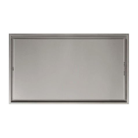
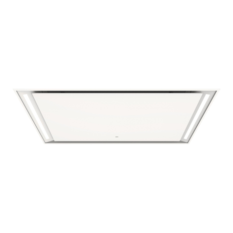
Novy 230 CLOUD User manual

NL Installatievoorschriften 2
FR
Instructions
d’installation 4
DE Montageanleitung 6
EN Operating and installation Instructions 8
230 10533 MA2
Novy Cloud
230 - 232

2
NL
1 VOORSCHRIFTEN VOOR VEILIGHEID
EN MONTAGE
Meer informatie over de Novy producten, accessoires
en diensten kunt u vinden op internet:
− België: www.novy.be
− Nederland: www.novynederland.nl
Dit is de montage instructie voor het toestel zoals op de
voorzijde is aangegeven. De gebruiksaanwijzing is een
apart boekje dat met het toestel is meegeleverd.
In deze montage instructie wordt gewerkt met een aan-
tal symbolen. Hieronder vind u de betekenis van deze
symbolen.
Symbool Betekenis Actie
Indicatie Toelichting van een
indicatie op de afzuigkap.
Info/
Waarschuwing
Dit symbool duidt op
een belangrijke tip of een
gevaarlijke situatie
Leef deze instructie na om letsel en materiële schade
te voorkomen.
Waarschuwingen voorafgaand montage
− Dit toestel voldoet aan de geldende veiligheidsvoor-
schriften. Ondeskundige montage kan echter persoonlijk
letsel en schade aan het toestel veroorzaken.
−
Het toestel is uitsluitend bedoeld voor huishoudelijk
gebruik (bereiding van voedingsmiddelen) met uitsluiting
van alle ander huishoudelijk, commercieel of industrieel
gebruik. Gebruik het toestel niet buitenshuis.
− Controleer de staat van het toestel en het montage-
materiaal zodra u ze uit de verpakking haalt. Neem
het toestel met zorg uit de verpakking. Gebruik geen
scherpe messen om de verpakking te openen.
− Installeer het toestel niet indien het beschadigd is en
richt u in dat geval tot Novy.
− Controleer aan de hand van tekening A of alle mon-
tagematerialen meegeleverd zijn. De vetfilters bevinden
zich in het toestel.
− Novy is niet aansprakelijk voor schade als gevolg van
onjuiste montage, onjuiste aansluiting, onjuist gebruik
of onjuiste bediening.
−
De installatie en de elektrische aansluiting van het toe-
stel dienen aan een erkende vakman toevertrouwd
te worden.
−
De veiligheid is alleen gewaarborgd bij een deskundige
montage volgens de montagehandleiding. De instal-
lateur is verantwoordelijk voor een goede werking op
de plaats van opstelling.
− Voor het eenvoudiger monteren van het toestel wordt
aangeraden dit met minimaal 2 personen uit te voeren.
−
Lees aandachtig de gebruiksaanwijzing en de montage
instructie vóór de installatie en ingebruikname van dit
toestel. Hierin vind u belangrijke informatie voor de
montage en gebruik van het toestel.
− Metalen onderdelen kunnen scherpe kantjes hebben
en u kunt zich eraan verwonden. Draag daarom bij het
monteren handschoenen die u daartegen beschermen.
Montage voorschriften van het toestel
−
Zorg dat de constructie waar het toestel aan of in wordt
gemonteerd over voldoende draagkracht beschikt.
−
Defecte of beschadigde onderdelen mogen alleen door
originele Novy onderdelen worden vervangen.
−
Hoe groter de afstand is tussen het toestel en de kook-
plaat, hoe minder gemakkelijk de kookdampen opge-
nomen worden door het toestel. Respecteer derhalve
de vermelde (advies)montagehoogte.
−
Om ervoor te zorgen dat de kookdampen optimaal
worden opgenomen, dient het toestel of de constructie
waarin het toestel wordt ingebouwd de kookplaat te
overdekken. Zorg bij een zelf gemaakte constructie
dat het toestel gecentreerd boven de kookplaat ge-
monteerd wordt.
−
Voor een optimale werking mag de kookplaat niet groter
zijn dan het toestel of de constructie waarin het toestel
is ingebouwd.
Recirculatie
De afzuigkap kan uitsluitend als recirculatie afzuigkap
worden gebruikt.
De kookdampen worden door de vetfilters en een geurfilter
gereinigd en weer teruggeleid in de keuken.
Luchttoevoer
Bij een toestel met recirculatie dient ook een minimale
ventilatie in de ruimte waar het toestel is opgesteld/
geplaatst aanwezig te zijn. De ventilatie kan geschieden
door de algemene ventilatie in de woning of door een
raam te kantelen of een deur te openen.
Elektrische aansluiting
−
Het toestel mag met de netstekker uitsluitend wor-
den aangesloten op een stopcontact met randaarde
(230V – 50Hz).
−
De veiligheid wordt enkel verzekerd wanneer het toestel
volgens de vereiste voorschriften op een aardleiding
is aangesloten.
−
Het toestel dient op elk gewenst moment van de stroom
te kunnen worden afgesloten.
−
Positioneer het stopcontact zodanig dat de netstekker
van het toestel eenvoudig aangesloten kan worden.

3
− Gebruik geen verlengkabel voor de aansluiting op het
elektrische net.
−
Elektrische schok: een defect toestel nooit inschakelen,
dit kan een elektrische schok veroorzaken. Neem de
netstekker uit het stopcontact of schakel deze uit bij
de groepenkast. Neem contact op met de service-
dienst van Novy.
−
Reparaties en vervangen van defecte of beschadigde
bedradingen mogen uitsluitend worden uitgevoerd door
technici welke zijn geïnstrueerd door Novy.
− Vocht dat in het toestel terecht is gekomen kan een
elektrische schok veroorzaken. Geen hogedrukreiniger
of stoomreiniger gebruiken.
2 ACCESSOIRES
Montageframe
Met het losse montageframe is het mogelijk om eenvoudig
een kleurencombinatie te maken.
De witte Cloud gecombineerd met een zwart montage-
frame of een zwarte Cloud gecombineerd met een wit
montageframe.
− Montageframe zwart 230.500
− Montageframe wit 230.510
Intouch
InTouch biedt de mogelijkheid om de Novy-afzuigkap te
bedienen vanaf de Novy InTouch inductiekookplaat. De
plafondunit kan standaard gecombineerd worden met
InTouch inductiekookplaten.
Kijk op de website voor de verschillende modellen van
inductiekookplaten met InTouch.
Meer informatie over de Novy producten, accessoires
en diensten kunt u vinden op internet:
België: www.novy.be
Nederland: www.novynederland.nl

4
FR
1 PRESCRIPTIONS DE SÉCURITÉ ET
D’INSTALLATION
Vous trouverez plus d’informations sur les produits,
accessoires et services Novy sur Internet:
www.novy.fr
Ceci est la notice de montage de l’appareil identifié en
première page. Le mode d’emploi est un livret séparé,
fourni avec l’appareil.
Cette notice de montage utilise un certain nombre de
symboles. Vous trouverez ci-dessous la signification de
ces symboles.
Symbole Signification Action
Indication Explication d'une indi-
cation apparaissant sur
l'appareil
Avertissement Ce symbole signale un
conseil important ou
une situation dange-
reuse
Respectez ces instructions pour éviter les blessures et
les dommages matériels.
Avertissements préalables au montage
− Cet appareil est conforme aux règles de sécurité en
vigueur. Toutefois, une installation non professionnelle
peut entraîner des blessures corporelles et endom-
mager l’appareil.
− L’appareil est exclusivement destiné à un usage do-
mestique (préparation d’aliments), à l’exclusion de tout
autre usage domestique, commercial ou industriel.
N’utilisez pas l’appareil en extérieur.
− Vérifiez l’état de l’appareil et du matériel de montage
dès que vous les sortez de l’emballage. Retirez l’ap-
pareil de l’emballage avec précaution. N’utilisez pas
de couteaux pointus pour ouvrir l’emballage.
−
Si l’appareil est endommagé, ne l’installez pas et
contactez Novy.
− Vérifiez sur base du schéma A que tout le matériel de
montage est inclus. Les filtres à graisse se trouvent
déjà dans l’appareil.
− Novy n’est pas responsable des dommages résultant
d’un montage, d’un raccordement, d’une utilisation ou
d’un maniement incorrects.
−
L’installation et le raccordement électrique de l’appareil
doivent être confiés à un professionnel qualifié.
− La sécurité n’est garantie que si l’appareil est correc-
tement installé conformément à la notice de montage.
L’installateur est responsable du bon fonctionnement
sur le lieu d’installation.
−
Afin de faciliter l’installation de l’appareil, il est recom-
mandé d’y procéder avec au moins 2 personnes.
−
Veuillez lire attentivement le mode d’emploi et la notice
de montage avant d’installer et de mettre en service cet
appareil. Vous y trouverez des informations importantes
pour le montage et l’utilisation de l’appareil.
− Les pièces métalliques peuvent présenter des arêtes
vives et peuvent occasionner des blessures. Dès lors,
portez des gants qui vous en préservent lors de l’as-
semblage.
Prescriptions de montage de l’appareil
−
Veillez à ce que la structure sur ou dans laquelle l’appareil
doit être monté ait une capacité de charge suffisante.
−
Les pièces défectueuses ou endommagées ne peuvent
être remplacées que par des pièces Novy d’origine.
−
Plus la distance entre l’appareil et la plaque de cuisson
est grande, plus l’aspiration des vapeurs de cuisson
par l’appareil sera difficile. Respectez donc la hauteur
de montage (recommandée) spécifiée.
− Pour que les vapeurs de cuisson soient aspirées de
manière optimale, l’appareil ou la structure dans laquelle
il doit être installé doit recouvrir la table de cuisson.
Dans le cas d’une structure réalisée soi-même, s’as-
surer que l’appareil est monté centré au-dessus de la
table de cuisson.
− Pour un fonctionnement optimal, la surface de cuis-
son ne doit pas être plus grande que l’appareil ou la
structure dans laquelle il est installé.
Recyclage
La hotte de cuisson ne peut être utilisée que comme une
hotte de recirculation.
Les vapeurs de cuisson sont nettoyées par les filtres à
graisse et un filtre à odeurs et sont renvoyées dans la
cuisine.
Arrivée d’air
Dans le cas d’un appareil avec recirculation, il doit éga-
lement y avoir un minimum de ventilation dans la pièce
où l’appareil est installé. La ventilation peut se faire en
activant la ventilation générale dans l’habitation ou en
entrouvrant une fenêtre ou en ouvrant une porte.
Raccordement électrique
−
L’appareil ne peut être branché que dans une prise de
courant avec broche de terre (230 V, 50 Hz).
−
La sécurité n’est garantie que si l’appareil est rac-
cordé à un conducteur de terre conformément à la
réglementation en vigueur.
−
L’appareil doit pouvoir être débranché de l’alimentation
électrique à tout moment.
− Positionnez la prise de courant murale de manière à
ce que la fiche secteur de l’appareil puisse être faci-
lement insérée.

5
−
N’utilisez pas de rallonge pour le branchement au secteur.
− Choc électrique : n’allumez jamais un appareil défec-
tueux, car cela pourrait provoquer un choc électrique.
Débranchez la fiche secteur de la prise de courant ou
déconnectez-la au niveau du tableau de distribution.
Contactez le service après-vente de Novy.
−
Les réparations et le remplacement du câblage défec-
tueux ou endommagé ne doivent être effectués que
par des techniciens formés par Novy.
−
L’humidité qui pénètre dans l’appareil peut provoquer
un choc électrique. N’utilisez pas de nettoyeur haute
pression ni de nettoyeur vapeur.
2 ACCESSOIRES
Cadre de montage
Avec le cadre de montage séparé, il est possible de créer
facilement une combinaison de couleurs.
Le Cloud blanc combiné à un cadre de montage noir ou
un Cloud noir combiné à un cadre de montage blanc.
− Cadre de montage noir 230.500
− Cadre de montage blanc 230.510
Intouch
InTouch permet de commander la hotte Novy à partir
de la table de cuisson à induction Novy InTouch. Ce
plafonnier est compatible avec les tables de cuisson
induction Novy In Touch.
Visitez le site web pour voir les différents modèles de
table de cuisson à induction avec InTouch.
Vous trouverez plus d’informations sur les produits,
accessoires et services Novy sur Internet:
www.novy.fr

6
DE
1 SICHERHEITS- UND
MONTAGEVORSCHRIFTEN
Weitere Informationen zu den Produkten, dem Zubehör
und den Dienstleistungen von Novy finden Sie im Internet
unter: www.novy-dunsthauben.de
Diese Broschüre enthält die Montageanleitung für das
Gerät, wie auf der Vorderseite angegeben. Die Gebrauchs
-
anweisung wurde dem Gerät in einer gesonderten Bro-
schüre beigefügt.
In dieser Montageanleitung werden einige Symbole ver-
wendet. Nachfolgend finden Sie eine Erklärung dieser
Symbole.
Symbol Bedeutung Aktion
Anzeige Erläuterung einer Anzeige auf
der Dunstabzugshaube.
Warnhinweis Dieses Symbol weist auf
einen wichtigen Tipp oder
eine gefährliche Situation hin.
Beachten Sie diese Anleitung, um Verletzungen und Sach-
schäden zu vermeiden.
Warnhinweise vor der montage
−
Dieses Gerät erfüllt die geltenden Sicherheitsvorschriften.
Eine unsachgemäße Montage kann jedoch zu Verlet-
zungen und Schäden am Gerät führen.
− Das Gerät ist nur für den Hausgebrauch (Zubereitung
von Lebensmitteln) bestimmt, unter Ausschluss aller
anderen haushaltlichen, gewerblichen und industriellen
Zwecke. Das Gerät darf nicht im Freien verwendet
werden.
−
Überprüfen Sie den Zustand des Geräts und des
Montagematerials, sobald Sie es aus der Verpackung
nehmen. Nehmen Sie das Gerät sorgfältig aus der Ver-
packung. Verwenden Sie zum Öffnen der Verpackung
keine scharfen Messer.
−
Installieren Sie das Gerät nicht, wenn es beschädigt ist,
und wenden Sie sich in diesem Fall an Novy.
−
Überprüfen Sie anhand der Zeichnung A , ob alle Mon-
tagematerialien vorhanden sind. Die Fettfilter befinden
sich in dem Gerät.
−
Novy haftet nicht für Schäden, die durch falsche Mon-
tage, falschen Anschluss, unsachgemäße Verwendung
oder falsche Bedienung entstehen.
− Die Installation und der elektrische Anschluss des Ge-
räts müssen von einem anerkannten Fachmann über-
nommen werden.
−
Die Sicherheit ist nur bei fachgerechter Installation ge-
mäß der Montageanleitung gewährleistet. Derjenige,
der das Gerät installiert, ist für den ordnungsgemäßen
Betrieb am Installationsort verantwortlich.
−
Zur einfacheren Montage des Gerätes wird empfohlen,
diese mit mindestens zwei Personen durchzuführen.
−
Lesen Sie die Gebrauchsanweisung und Montageanlei-
tung sorgfältig durch, bevor Sie dieses Gerät installieren
und in Betrieb nehmen. Darin sind wichtige Informa-
tionen in Bezug auf die Installation und Verwendung
des Geräts enthalten.
−
Metallteile können scharfe Kanten haben, an denen
Sie sich verletzen können. Tragen Sie bei der Montage
Handschuhe, die Sie vor Verletzungen schützen.
Montagevorschriften des geräts
− Stellen Sie sicher, dass die Konstruktion, auf der das
Gerät montiert wird, eine ausreichende Tragfähigkeit
besitzt.
− Defekte oder beschädigte Teile dürfen nur durch Ori-
ginalteile von Novy ersetzt werden.
−
Je größer der Abstand zwischen Gerät und Koch-
feld, desto weniger Kochdämpfe werden vom Gerät
aufgenommen. Beachten Sie daher die angegebene
(empfohlene) Montagehöhe.
− Um eine optimale Absorption der Kochdämpfe zu ge-
währleisten, muss das Gerät oder die Konstruktion, in
die das Gerät eingebaut wurde, das Kochfeld abdecken.
Stellen Sie bei einer selbst hergestellten Konstruktion
sicher, dass das Gerät mittig über dem Kochfeld mon-
tiert wird.
−
Für eine optimale Leistung darf das Kochfeld nicht größer
sein als das Gerät oder die Konstruktion, in der das
Gerät installiert ist.
Umluft
Die Dunstabzugshaube kann nur als Umluft-Dunstab-
zugshaube verwendet werden.
Die Kochdämpfe werden durch die Fettfilter und einen
Geruchsfilter gereinigt und in die Küche zurückgeführt.
Luftzufuhr
Bei einem Gerät mit Rezirkulation muss in dem Raum, in
dem das Gerät installiert / aufgestellt wurde, eine Min-
destbelüftung gegeben sein. Die Belüftung kann über die
allgemeine Belüftung oder ein geöffnetes Fenster oder
eine geöffnete Tür erfolgen.
Elektrischer anschluss
− Das Gerät darf nur mit einem Netzstecker an eine ge-
erdete Steckdose angeschlossen werden (230V - 50Hz).
−
Die Sicherheit ist nur dann gewährleistet, wenn das Gerät
vorschriftsmäßig an einen Schutzleiter angeschlossen ist.
−
Das Gerät muss jederzeit vom Stromnetz getrennt
werden können.
−
Positionieren Sie die Steckdose so, dass der Netzstecker
des Geräts problemlos angeschlossen werden kann.

7
−
Verwenden Sie kein Verlängerungskabel für den An-
schluss an das Stromnetz.
−
Elektrischer Schlag: Schalten Sie niemals ein defektes
Gerät ein, da dies einen elektrischen Schlag verursachen
kann. Ziehen Sie den Netzstecker aus der Steckdose
oder schalten Sie ihn am Gruppenschrank aus. Wenden
Sie sich an den Kundendienst von Novy.
−
Der Austausch defekter oder beschädigter Kabel sowie
Reparaturen dürfen nur durch von Novy angewiesene
Techniker vorgenommen werden.
−
In das Gerät eingedrungene Feuchtigkeit kann einen
elektrischen Schlag verursachen. Verwenden Sie keinen
Hochdruck- bzw. Dampfreiniger.
2 ZUBEHÖR
Montagerahmen
Mit dem separaten Befestigungsrahmen ist es möglich,
auf einfache Weise eine Farbkombination zu erstellen.
Die weiße Cloud kombiniert mit einem schwarzen Be-
festigungsrahmen oder eine schwarze Cloud kombiniert
mit einem weißen Befestigungsrahmen.
− Befestigungsrahmen schwarz 230.500
− Befestigungsrahmen weiß 230.510
Intouch
InTouch bietet die Möglichkeit, die Novy-Dunstabzugs-
haube von der Novy InTouch Induktionskochplatte aus
zu bedienen.
Die Deckeneinheit kann standardmäßig mit allen Novy
InTouch Induktionskochfeldern kombiniert werden.
Auf der Website finden Sie verschiedene Induktionskoch
-
platten-Modelle mit InTouch.
Weitere Informationen zu den Produkten, dem Zubehör
und den Dienstleistungen von Novy finden Sie im Internet
unter: www.novy-dunsthauben.de

8
EN
1 SAFETY AND ASSEMBLY
REGULATIONS
Further information on Novy products, accessories and
services may be found on the internet: www.novy.co.uk
These are the installation instructions for the appliance
as shown on the front. The directions for use are in a
separate booklet supplied with the appliance.
These installation instructions make use of a number of
symbols. The meanings of the symbols are shown below.
Symbol Meaning Action
Indication Explanation of an
indication on the hood.
Warning This symbol indicates
an important tip or a
dangerous situation
Observe this instruction in order to prevent injury and
damage to property.
Warnings before installation
−
This appliance complies with the applicable safety
instructions. However, inexpert installation may cause
personal injury or damage to the appliance.
−
The appliance is intended exclusively for household
use (preparation of food) and excludes all other do-
mestic, commercial or industrial use. Do not use the
appliance outside.
−
Check the condition of the appliance and the installation
fittings as soon as you remove them from the packag-
ing. Remove the appliance from the packaging with
care. Do not use sharp knives to open the packaging.
−
Do not install the appliance if it is damaged, and in
that case inform Novy.
− Check on the basis of the drawing A that all the ma-
terials for installation have been supplied. The grease
filters are in the appliance.
− Novy is not liable for damage resulting from incorrect
assembly, incorrect connection, incorrect use or in-
correct operation.
−
The installation and electrical connection of the appli-
ance should be left to a recognised expert.
−
Safety is guaranteed only with expert installation in
accordance with the installation manual. The installing
technician is responsible for proper operation at the
installation location.
− For easier installation of the appliance, it is advisable
to carry it out with at least 2 people.
−
Read the directions for use and the installation instruc-
tions before installing and using this appliance. You
will find important information here for the assembly
and use of the appliance.
− Metal parts may have sharp edges, and you may in-
jure yourself on them. For that reason, wear protective
gloves during installation.
Installation instructions for the appliance
− Ensure that the structure on or in which the appliance
is to be installed can bear its weight.
−
Faulty or damaged parts may only be replaced by
original Novy parts.
− The greater the distance between the appliance and
the hob, the less easily the cooking vapours can be
taken up by the appliance. For this reason, pay heed
to the stated (recommended) installation height.
− In order to ensure that the cooking vapours are taken
up in an optimal way, the appliance, or the structure into
which the appliance is being installed, should extend
over the hob. When using your own structure, ensure
that the appliance is installed centred above the hob.
−
For optimal operation, the hob should not be larger
than the appliance or the structure into which the ap-
pliance is installed.
Recirculation
The cooker hood can only be used as a recirculation
cooker hood.
The cooking vapours are cleaned by the grease filters
and an odour filter and returned to the kitchen.
Air supply
With an appliance with recirculation, there must be a
minimum of ventilation in the room where the appliance
has been installed / is positioned. Ventilation can be
provided by the overall ventilation in the home or by
tilting a window or opening a door.
Installation instructions for the outlet
−
The appliance may only be connected with the power
plug to a socket with an earth (230 V – 50 Hz).
−
Safety is only assured when the appliance is connected
to an earth cable in accordance with the instructions
laid down.
− The appliance must be able to be disconnected from
the power at any desired point.
− Position the socket in such a way that the power plug
of the appliance can be inserted easily.
− Do not use an extension cable for the connection to
the electrical mains.
−
Electric shock: never switch on a faulty appliance, this
could cause an electric shock. Take the power plug out
of the socket, or switch off at the distribution cabinet.
Contact the Novy service department.
− Repairs and replacing faulty or damaged wiring must
only be carried out by technicians who have undergone
instruction by Novy.
−
Moisture that has got into the appliance may cause an
electric shock. Do not use a high pressure or steam
cleaner.

9
2 ACCESSORIES
Mounting frame
With the separate mounting frame it is possible to easily
create a colour combination.
The white Cloud combined with a black mounting frame
or a black Cloud combined with a white mounting frame.
− Mounting frame black 230.500
− Mounting frame white 230.510
Intouch
InTouch offers you the possibility to control the Novy
cooker hood from the Novy InTouch induction cooking
plate. The ceiling hood may, as a default, be combined
with InTouch induction cooking plates.
Visit the website for the different models of induction
cooking plates with InTouch.
Further information on Novy products, accessories and
services may be found on the internet:
www.novy.co.uk

10
NL
Haal de afzuigkap
NIET direct uit de verpak-
king. Plaats de doos op het
werkblad ter hoogte waar
de afzuigkap gemonteerd
wordt. Let op de beschrij-
ving op de verpakking en
open deze aan de juiste
zijde voor een eenvoudige
montage.
De advies afstand tus-
sen werkblad en onderzijde
afzuigkap met elektrische-
of keramische kookplaat is
minimaal 600mm en maxi-
maal 1600mm. De advies
afstand tussen werkblad en
onderzijde afzuigkap met
gas of inductie kookplaat is
minimaal 650mm en maxi-
maal 1600mm.
Door het aanzienlij-
ke eigen gewicht van de
afzuigkap dient het plafond
over voldoende draagkracht
te bezitten.
Positioneer het stop-
contact zodanig dat deze
achter de plafondunit valt.
DU
Nehmen Sie die Dunst-
abzugshaube NICHT direkt aus
der Verpackung heraus. Stellen
Sie den Karton dort auf die
Arbeitsplatte, wo die Dunst-
abzugshaube montiert werden
soll. Beachten Sie die Beschrei-
bung auf der Verpackung und
öffnen Sie diese an der richtigen
Seite, für eine einfache Montage.
Die empfohlene Mon-
tagehöhe bei einem Elekt-
ro- oder Keramikkochfeld
beträgt mindestens 600 mm
und höchstens 1600 mm. Die
empfohlene Montagehöhe
bei einem Gas- oder Indukti-
onskochfeld beträgt mindes-
tens 650 mm und höchstens
1600 mm.
Aufgrund des beträcht-
lichen Eigengewichts der
Dunstabzugshaube muss
die Decke eine ausreichende
Tragfähigkeit aufweisen.
Positionieren Sie die
Wandsteckdose so, dass sie
sich hinter der Deckeneinheit
befindet.
FR
Ne retirez PAS tout de
suite la hotte de son em-
ballage. Placez la boîte sur
le plan de travail à hauteur
de l’endroit où la hotte sera
montée. Faites attention aux
inscriptions sur l’emballage
et ouvrez celui-ci du bon
côté pour faciliter le mon-
tage.
La hauteur de mon-
tage recommandée avec
une table de cuisson
électrique ou céramique
est de 600 mm minimum
et 1600mm maximum. La
hauteur de montage avec
une table de cuisson au gaz
ou à induction est de 650
mm minimum et 1600 mm
maximum.
Compte tenu du poids
important de la hotte, il
convient de s’assurer que le
plafond possède une capa-
cité de charge suffi sante.
Positionnez la prise
murale de manière à ce
qu'elle se trouve derrière
l'unité de plafond.
EN
Do NOT immediately
remove the hood from the
packaging. Place the box
on the table top at the place
where the hood is to be
mounted. Take notice of the
description on the packag-
ing and open this on the cor-
rect side for easy mounting.
The recommended
mounting height for an
electric or ceramic cooking
plate is min. 600 mm and
max. 1600 mm. The mount-
ing height for a gas or
induction cooking plate is
min. 650 mm and max.
1600 mm.
Because of the
substantial own weight of
the hood, the ceiling must
have sufficient load bearing
capacity.
Position the wall sock-
et in such a way that it is
behind the ceiling unit.
2
1
3
A
1x 990.271
7x 906.192
7x 906.143
7x 906.055
11x 906.116
2x 230.020
1x 230.060
(set)
1x 840049

11
NL 3 INSTALLATIE
1
• Duid op het plafond het middelpunt van de
afzuigkap aan. Het middelpunt dient gecentreerd
boven de kookplaat te liggen.
•
Teken in de lengte richting de middellijn.
2
• Neem de montageplaat uit de verpakking en
plaats deze gecentreerd vanuit de kookplaat
gezien tegen het plafond. Zorg dat de getekende
middellijn overeen komt met de uitsparingen in
de montage plaat.
• Teken, boor en bevestig eerst de middelste
schroef op het aangegeven middelpunt.
•
Draai de schroef nog niet geheel vast.
Let op dat de elektrische aansluiting bin-
nen de linker of rechter opening valt van
de montageplaat.
3• Teken de 6 montage punten af (in de 4 hoeken
en 2 in het midden van elke lange zijde).
• Draai voorzichtig de montageplaat een kwartslag
om de 6 bevestigingsgaten te boren. Draai de
montageplaat weer terug en bevestig de 6
schroeven.
•
De montage plaat is in totaal met 7 schroeven
aan het plafond bevestigd.
DU 3 INSTALLATION
1
• Markieren Sie an der Decke die Mitte der
Dunstabzugshaube. Die Mitte sollte sich mittig
über dem Kochfeld befinden.
• Ziehen Sie die Mittellinie in der Längsrichtung.
2
• Nehmen Sie die Montageplatte aus der Verpackung
und halten Sie sie vom Kochfeld aus gesehen
mittig gegen die Decke. Sorgen Sie dafür, dass
die angezeichnete Mittellinie mit den Löchern
in der Montageplatte übereinstimmt.
• Markieren Sie das Loch für die mittlere Schraube
an dem angegebenen Mittelpunkt, bohren Sie
das Loch und setzen Sie die Schraube ein.
• Drehen Sie die Schraube noch nicht vollständig
fest.
Achten Sie darauf, dass die elektrischen
Anschlüsse in der linken oder rechten
Öffnung der Montageplatte liegen.
3
• Markieren Sie die sechs Befestigungspunkte (in
den vier Ecken und zwei verteilt über die beiden
langen Seiten).
• Drehen Sie die Montageplatte vorsichtig um
einer Vierteldrehung, um die sechs Löcher zu
bohren. Drehen Sie die Montageplatte wieder
zurück und schrauben Sie die sechs Schrauben
ein.
• Die Montageplatte ist mit insgesamt sieben
Schrauben an der Decke befestigt.
FR 3 INSTALLATION
1
• Repérez au plafond le point central de la hotte.
Le point central doit être centré au dessus de
la table de cuisson.
• Tracez la ligne médiane dans le sens de la
longueur.
2
• Retirez la plaque de montage de l’emballage et
placez-la contre le plafond de telle façon qu’elle
soit centrée par rapport à la table de cuisson.
Assurez-vous que la ligne médiane que vous
avez tracée correspond aux évidements dans
la plaque de montage.
• Tracez un repère, percez le plafond et fixez
d’abord la vis centrale sur le point central indiqué.
• Ne serrez pas encore totalement cette vis.
Assurez-vous que le raccordement électri-
que passe par l’ouverture gauche ou droite
de la plaque de montage.
3• Repérez les 6 points de montage (4 aux angles
et 2 au milieu des côtés longs).
• Tournez prudemment la plaque de montage d’un
quart de tour pour pouvoir percer les 6 trous de
fixation. Retournez la plaque de montage d’un
quart de tour dans l’autre sens et fixez les 6 vis.
• La plaque de montage est fixée au plafond par
l’intermédiaire de 7 vis au total.
EN 3 INSTALLATION
1
• Indicate the centre point of the extractor hood on
the ceiling. The centre point should be centred
above the hob.
• Draw in the longitudinal direction of the centre
line.
2
• Take the mounting plate from the packaging and
place it in the centre as seen from the cooking
plate against the ceiling. Make sure that the
drawn centre line is aligned with the cut-aways
in the mounting plate.
• First draw, drill and fasten the central screw at
the indicated middle point.
• Do not fully tighten the screw yet.
Make sure that the electric connection falls
within the left or right opening of the moun-
ting plate.
3
• Mark the 6 mounting points (in the 4 corners
and 2 in the middle of each long side).
• Carefully turn the mounting plate a quarter turn
in order to be able to drill the 6 fastening holes.
Turn back the mounting plate and fasten the 6
screws.
• The mounting plate is attached to the ceiling
with 7 screws.

12
4
5a
5b
Voorkant - Face avant - Front - Vorderseite

13
NL
4
Aan de afzuigkap zijn 4 metalen kabels bevestigd.
Plaats deze 4 kabels in de voorziene opening in
de montageplaat.
5a
De minimale afstand tussen de linker- en/of
rechterzijde van de Cloud tot aan een wand
of venster mag niet kleiner zijn dan 50cm.
Gebruik enkel de luchtgeleider (990.271) in de
volgende situatie:
•Afstand tussen de linker- en/ of rechterzijde van
de kap tot aan een wand of venster is tussen
de 50 tot 100 cm. Ga anders verder naar stap
6.
• Bij het toepassen van de luchtgeleider, dient
aan de voorzijde waar de lucht geblazen wordt
minimaal een afstand van 100 cm tot aan een
wand te zijn.
• Deze geleider zorgt ervoor dat de lucht niet
rechtstandig naar links of rechts uitgeblazen
wordt, maar afgebogen met een hoek van 70°
naar de voorkant van de afzuigkap.
5b
Bevestig de geleider met twee schroeven (906.116)
vast in de afzuigkap.
DU
4An der Dunstabzugshaube sind vier Metallkabel
befestigt. Platzieren Sie diese vier Kabel in der
vorgesehenen Öffnung in der Montageplatte.
5a
Der Mindestabstand zwischen linker und/
oder rechter Seite der Cloud und einer
Wand oder einem Fenster sollte nicht weni-
ger als 50 cm betragen.
Verwenden Sie in der folgenden Situation nur
die Luftführung (990.271):
• Der Abstand zwischen linker und/oder rechter
Seite der Dunstabzugshaube und einer Wand
oder einem Fenster beträgt 50 bis 100 cm.
Fahren Sie andernfalls mit Schritt 6 fort.
• Bei Verwendung der Luftführung muss auf der
Vorderseite, wo die Luft ausgeblasen wird, der
Abstand zu einer Wand mindestens 100 cm
betragen.
• Diese Führung sorgt dafür, dass die Luft nicht
rechtwinklig nach links oder rechts ausgeblasen
wird, sondern in einem Winkel von 70° zur
Vorderseite der Haube abgelenkt wird.
5b Befestigen Sie die Führung mit zwei Schrauben
(906.116) in der Dunstabzugshaube.
FR
4
La hotte aspirante comporte 4 câbles métalliques.
Insérez ces 4 câbles dans l’ouverture prévue à
cet effet dans la plaque de montage.
5a
La distance entre le côté gauche et/ou le
côté droit du Cloud et le mur ou la fenêtre
ne doit jamais être inférieure à 50 cm.
Utilisez le déflecteur d’air (990.271) unique-
ment dans la situation suivante :
• La distance entre le côté gauche et/ou le côté
droit de la hotte et le mur ou la fenêtre est 50
à 100 cm. Autrement, vous pouvez passer à
l’étape 6.
• Quand le déflecteur d’air est appliqué, une
distance minimale de 100 cm doit être prévue
jusqu’à un mur.
• Grâce à ce déflecteur, le flux d’air ne sera pas
dirigé en ligne droite vers la gauche ou vers la
droite mais sera dévié à un angle de 70° vers
l’avant de la hotte aspirante.
5b
Fixez le déflecteur à la hotte à l’aide de 2 vis
(906.116).
EN
44 metal cables have been attached to the hood.
- Place these 4 cables in the opening provided
in the mounting plate.
5a
The minimum distance between the left
and/or right side of the Cloud up to a wall
must be greater than 50 cm.
Only use the air conductor (990.271) in the
following situation:
• The distance between the left and/or right
side of the hood up to a wall must be between
50 cm and 100 cm. Otherwise go on to step 6.
• When attaching the air conductor, the front
where the air is blown must be at 100 cm from
a wall.
• This conductor makes sure the air is not blown
out vertically to the left or the right, but that it
bends away to the front side of the hood at an
angle of 70°.
5b Fasten the conductor with 2 screws (906.116) in
the hood.

14
7
6

15
NL
6• Met behulp van de metalen kabels kan de kap
omhoog getakeld worden. Op de plaats waar
de kabel de afzuigkap in gaat zit de adjuster.
• Als deze adjuster wordt ingedrukt kan de kabel
uitgeschoven worden. Zodra de adjuster niet meer
ingedrukt is zal de kabel vergrendeld zijn. Op
dat moment kan de kabel nog wel ingeschoven
worden. Zorg dat de kabels verdwijnen in de
afzuigkap.
•
Stop ongeveer 10cm onder de montageplaat.
• Nu kan de elektrische aansluiting gemaakt
worden.
Let op, niet onder spanning monteren. Zorg
dat de spanning afge
sloten is. En zorg er-
voor dat de aan/uit schakelaar in uit positie
staat.
Na de elektrische aansluiting takel of druk de
afzuigkap geheel in de montageplaat.
7Bevestig de afzuigkap in de montageplaat door
aan voorzijde 4, aan achterzijde 5 schroeven
(906.116) vast te draaien.
DU
6
• Mit Hilfe der Metallkabel kann die Dunstabzugshaube
hochgezogen werden. An der Stelle, an der die
Kabel in die Dunstabzugshaube geführt werden,
befinden sich der Einsteller.
• Wenn dieser Einsteller eingedrückt wird, kann
das betreffende Kabel herausgeschoben werden.
Sobald der Einsteller nicht mehr eingedrückt wird,
wird das Kabel blockiert. Das Kabel kann dann
jedoch noch hineingeschoben werden. Sorgen Sie
dafür, dass die Kabel in der Dunstabzugshaube
verschwinden.
• Stoppen Sie etwa 10 cm unter der Montageplatte.
• Jetzt kann elektrische Verbindung hergestellt
werden.
Achtung - nicht unter Spannung montieren.
Achten Sie darauf, dass die Stromversor-
gung abgeschaltet ist. Stellen Sie sicher,
dass der Ein/Aus-Schalter auf „Aus“ steht.
Nach dem Herstellen der elektrischen Verbindung
können Sie die Dunstabzugshaube vollständig in
die Montageplatte ziehen oder drücken.
7
Befestigen Sie die Dunstabzugshaube in der
Montageplatte, indem Sie die Schrauben auf
der Vorderseite (4x 906.116) und Rückseite
(5x 906.116).
FR
6
• La hotte peut être hissée en hauteur à l’aide des
câbles métalliques. Le dispositif d’ajustement
se trouve à l’endroit où le câble pénètre dans
la hotte.
• Une pression sur ce dispositif d’ajustement permet
de dégager le câble. Une fois que la pression
sur ce dispositif d’ajustement est relâchée, le
câble est verrouillé. Mais il est toujours possible
d’y insérer le câble. Veillez à ce que les câbles
disparaissent dans la hotte.
• Arrêtez le levage à environ 10 cm sous la plaque
de montage.
• Vous pouvez à présent réaliser le raccordement
électrique.
Attention, ne procédez pas au montage si
l’installation est sous tension. Assurez-vous
que le courant est bien coupé. Vérifiez si
l’interrupteur Marche/Arrêt est dans la
position Arrêt.
Une fois le raccordement électrique réalisé,
hissez ou poussez la hotte entièrement dans
la plaque de montage.
7
Fixez la hotte dans la plaque de montage en
serrant les vis sur le côté avant (4x 906.116) et
le côté arrière (5x 906.116).
EN
6
• The hood can be hoisted up using the metal
cables. The adjuster can be found at the place
where the cable enters the hood.
• The cable can be extended by pressing this
adjuster. The cable will be locked as soon as
the adjuster is no longer pressed. The cable can
still be slid in at this moment. Make sure that
the cables disappear in the hood.
•
Stop about 10 cm below the mounting plate.
•
The electric connection can now be made.
Attention, do not carry out any mount-
ing activities while the power supply is
switched on. Ensure the power supply has
been switched off. And ensure the on/off
switch is in the off position.
After having made the electric connection, hoist
or press the hood fully into the mounting plate.
7
Fasten the hood in the mounting plate by tightening
the screws on the front side (4x 906.116) and rear
side (5x 906.116).

16
10
9
8a 8b

17
NL
8a Haak de onderplaat in de scharnieren, dit doe je
door de onderplaat ongeveer 90° ten opzichte
van de bovenplaat te houden.
8b
Normaal is het scharnier erop voorzien dat wanneer
je de onderplaat rustig loslaat, deze blijft hangen
onder een hoek van ongeveer 87°. Maar om
het vallen tegen te gaan is het verplicht om de
onderplaat vast te houden.
9
Zorg ervoor dat beide delen mooi in elkaar zijn
gehaakt.
10
• Klik de demper vast aan de onderplaat door met
één hand de onderplaat vast te houden en met
het andere hand de demper te bedienen.
• Verwijder het plastic van de filters. Plaats in de
aluminium vetfilters (230.020) de monoblock
filters (230.060).
Om de afzuigkap in te schakelen, moet
eerst de aan/uit schakelaar geactiveerd
worden. Deze wordt uitgeschakeld bij
service van het toestel. De knop bevindt
zich aan de voorkant, boven het feedback
display.
DU
8a
Haken Sie die Bodenplatte in die Scharniere,
indem Sie die Bodenplatte in einem Winkel von
ca. 90° zu der oberen Platte halten.
8b
Das Scharnier ist so konstruiert, dass die Bodenplatte
normalerweise in einem Winkel von ca. 87° hängen
bleibt, wenn Sie sie langsam loslassen. Um aber
auf jeden Fall zu verhindern, dass die Bodenplatte
herunterfällt, muss sie festgehalten werden.
9
Stellen Sie sicher, dass beide Teile korrekt ineinander
greifen.
10
• Rasten Sie den Dämpfer an der Bodenplatte
ein, indem Sie die Bodenplatte mit einer Hand
festhalten und mit der anderen Hand den Dämpfer
betätigen.
• Entfernen Sie den Kunststoff von den Filtern.
Legen Sie die Monoblockfilter (230.060) in die
Aluminium-Fettfilter (230.020).
Zum Einschalten der Dampfabzugshaube
muss zuerst der Ein/Aus-Schalter akti-
viert werden. Dieser Schalter wird bei der
Wartung des Geräts deaktiviert. Die Taste
befindet sich auf der Vorderseite über dem
Feedback-Display.
FR
8a Accrochez la plaque de fond aux charnières en
orientant la plaque de fond en un angle de 90°
environ par rapport à la plaque supérieure.
8b
Normalement, la charnière devrait s’accrocher de
sorte que la plaque de fond reste suspendue en
un angle de 87° environ quand elle est relâchée
prudemment. Cependant, afin de prévenir que
la plaque de fond tombe par terre, elle doit être
maintenue.
9Les deux éléments doivent être bien emboîtés.
10 • Engagez l’amortisseur dans la plaque de fond
en tenant la plaque de fond d’une main et en
actionnant l’amortisseur de l’autre main.
• Retirez le film plastique des filtres. Placez les
filtres à graisse en aluminium (230.020) et les
filtres Monoblock (230.060).
L'Afin de pouvoir mettre en marche la hotte,
il faudra tout d’abord activer l’interrupteur
Marche/Arrêt. Ce dernier est désactivé lors
de l’entretien de l’appareil. Ce bouton se
trouve à l’avant, au-dessus de l’affichage
de l’écran.
EN
8a
Hook the lower plate in the hinges by keeping the
lower plate in a position that is approximately 90°
relative to the upper plate.
8b
Normally, when the lower plate of the hinge is
gently released, the hinge will continue to hang at
an angle of approximately 87°. However, in order
to prevent it from falling, the lower plate must be
held.
9
Make sure both elements are well hooked together.
10
• Attach the damper by clicking it to the lower
plate by holding the lower plate with one hand
and operating the damper with the other.
• Remove the plastic from the filters. Place the
aluminium fat filters (230.020) and the monoblock
filters (230.060).
In order to turn on the hood, the on/off
switch must be activated first. This is
disabled for servicing the device. The knob
is located on the front, above the feedback
display.

18
Afmetingen - Dimensions - Abmessungen - Dimensions
230, 232

19

NOVY nv behoudt zich het recht voor te allen tijde en zonder voorbehoud de constructie en de prijzen van haar producten te wijzigen.
NOVYSA se réserve le droit de modifier à tout moment et sans réserve la fabrication et les prix de ses produits.
Die NOVY AG behält sich das Recht vor, zu jeder Zeit und ohne Vorbehalt die Konstruktion und die Preise ihrer Produkte zu ändern.
NOVY nv reserves the right at any time and without reservation to change the structure and the prices of its products.
NOVY nv
Noordlaan 6
B - 8520 KUURNE
Tel. 056/36.51.00
Fax 056/35.32.51
E-mail: novy@novy.be
http://www.novy.be
France: Tél: 0320.940662
Deutschland und Österreich: Tel: +49 (0)511.54.20.771
Nederland: Tel.: +31 (0)88-0119110
United Kingdom: +44 (0)207 866 2493
España: Tel.: +34 938 700 895
Italia: Tel.: +39 039.20.57.501
Other manuals for 230 CLOUD
4
This manual suits for next models
1
Table of contents
Languages:
Other Novy Ventilation Hood manuals

Novy
Novy Pureline Cubic 6831 User manual

Novy
Novy 780 Fusion+ User manual

Novy
Novy 6830/16 User manual

Novy
Novy Panorama Pro 1821 User manual

Novy
Novy Fusion 680 User manual

Novy
Novy Pureline Pro 6930 User manual

Novy
Novy 7600.400 User manual

Novy
Novy 828 User manual

Novy
Novy Panorama 1821 User manual

Novy
Novy 230 CLOUD User manual