Seav BeLED User manual
BeLED Flashing/Acoustic Beacon
Flashing Beacon with integrated acoustic warning device,
available in various power supply voltage models, for visual
and acoustic signalling for movement automations such as
gates, garage doors and more.
- Mod. BeLED 230VAC : 23 V~ 5 /6 Hz 4W max.
- Mod. BeLED 12-24V AC-DC : 12-24V AC-DC 4W max.
TECHN CAL DATA
- Power supply: see model
- 4 x 1W LED : 4W Max.
- Working temperature: -1 ÷55°C
- Dimensions: 14 x 1 x 7 mm.
- Container: PMMA - ABS UL94V- ( IP54 )
NSTALLAT ON OF THE FLASH NG BEACON
For excellent functioning, it is very important to choose the
place of installation carefully. Verify that the chosen surface is
capable of guaranteeing stable fixing. Verify that the chosen
position can be accessed easily for future maintenance
operations.
N T AL FUNCT ON NG COND T ON
The device must be exclusively connected to a source of
power that is suitable based on the model that was purchased;
a flashing electronic circuit is already integrated inside of it.
OPERAT NG FEATURES:
The flashing beacon is made of a transparent dome that
protects internal circuits and correctly diffuse light emitted by
the LEDs, and a base used for fixing it and passing cables.
When the device is active it warns the user that automation is
in movement using the luminous and acoustic signals,
depending on the settings.
SOUND SETT NGS:
Using the J1 Jumper it is possible to activate or
deactivate the acoustic signal as follows:
J1 not inserted: the device is supplied from the factory
in this mode. The flashing is accompanied by an acoustic
signal whose tone and level is high.
J1 position 1 - 2: the flashing is accompanied by an
acoustic signal whose tone and level is lower.
J1 position 2 - 3: the acoustic signal is disabled.
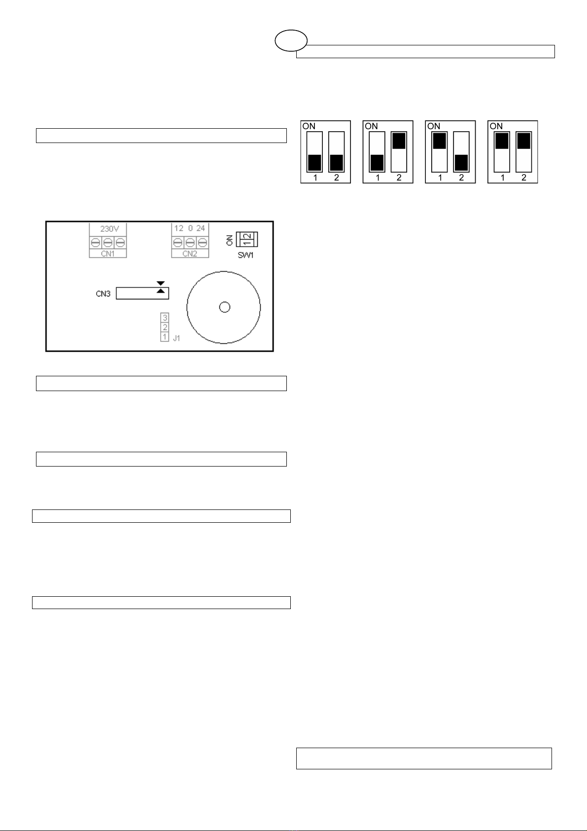
MANOEUVRE COUNTER SETT NGS:
Based on the position of the SW1 dip switches, the device
counts a determined number of manoeuvres (switch on) until is
signals the need for maintenance. Once the set number of
manoeuvres has been reached, flashing is replaced by a fixed
light.
Counter = OFF 5,000 cycles 10,000 cycles 20,000 cycles
Counter = OFF: the device is supplied from the factory
with the manoeuvre counter disabled. The flashing
beacon will continue to work without any limit in
manoeuvres, with flashing and acoustic signals,
depending on the settings. Activate the flashing beacon
at least once in this mode to reset the manoeuvre
counter.
No. 5,000 cycles: The device functions normally with
flashing and acoustic signalling, if set, until it reaches
5, cycles (switch on), subsequently it continues the
visual and acoustic signalling, depending on the settings,
but the light it emits is fixed and no longer intermittent.
This state remains until the switches are brought to OFF
and the device is activated at least once. In order to start
a new count, set the SW1 Switch once again at the
desired number of manoeuvres.
No. 10,000 cycles: The device functions normally with
flashing and acoustic signalling, if set, until it reaches
1 , cycles (switch on), subsequently it continues the
visual and acoustic signalling, depending on the settings,
but the light it emits is fixed and no longer intermittent.
This state remains until the switches are brought to OFF
and the device is activated at least once. In order to start
a new count, set the SW1 Switch once again at the
desired number of manoeuvres.
No. 20,000 cycles: The device functions normally with
flashing and acoustic signalling, if set, until it reaches
2 , cycles (switch on), subsequently it continues the
visual and acoustic signalling, depending on the settings,
but the light it emits is fixed and no longer intermittent.
This state remains until the switches are brought to OFF
and the device is activated at least once. In order to start
a new count, set the SW1 Switch once again at the
desired number of manoeuvres.
MPORTANT FOR THE NSTALLER
1 Rev. 1. 26/ 5/2 1
GB

−The product does not have any type of isolating device for
the 230 Vac line. It will therefore be the responsibility of the
installer to arrange an isolating device inside the plant. It
must be positioned where it can be protected from accidental
closing, according to that prescribed in point 5.2. of EN
12453.
−Wiring of the various electrical components outside of the
product must be carried out in compliance with that
prescribed in Standard EN 60204-1 and its amendments at
point 5.2.7 of EN 12453. Power supply and connection
cables must be fixed using the cable glands that can be
supplied as an optional.
−Pay attention while making holes in the outside casing, when
passing cables for connection and power supply and
assembling the cable glands, that everything is installed in a
way that keeps IP protection characteristics of the panel
unchanged as much as possible.
−Pay careful attention when fastening the cables so that they
are anchored in a manner that is stable.
− The back casing is not equipped with suitable
predispositions for fixing to a wall (predisposition for holes for
fixing using anchors or holes for fixing using screws). Plan
and implement necessary solutions to achieve an installation
that does not alter the IP protection.
MPORTANT FOR THE NSTALLER
- ATTENTION: keep this instruction manual and respect the
important safety prescriptions contained herein. The non
compliance with the prescriptions may cause damages and
serious accidents.
- The device must never be used by children or persons with
reduced physical-psychological abilities, unless supervised or
trained on the functioning and the use modalities.
- Frequently examine the system to detect any signs of
damaging. Do not use the device if a repair intervention is
necessary.
Attention
All operations which require the opening of the casing (cables
connection, programming, etc.) must be carried out by expert
personnel during installation. For any further operation which
requires the casing to be re-opened (re-programming, repair or
installation changes) contact the after-sales assistance.
SEAV S.r.l. declares that the product:
BeLED 230VAC - BeLED 12-24V AC-DC
is in compliance with the specifications of Directives
EMC 2 4/1 8/EC, LVD 2 6/95/EC.
2 Rev. 1. 26/ 5/2 1


