Secced SC-402-6 User manual

Thanks for choosing SECCED’s Traveler Crane
For your reference
SN
Date of purchase
Name and address of the distributor
1

Safety Guideline
1. The assembly instructions must be read and understood before set-up or
operation. The crane may only be assembled in accordance with the
manufacturer’s instruction manual. The manufacturer’s technical specifications
and limits must be adhered to all times and in no way exceeded.
2. The Traveler Crane may only be set-up or operated by trained and experienced
personnel. To avoid misuse by untrained personnel, the crane should be
dismantled when not in use or under supervision.
3. The crane may not be assembled or operated under influence of alcohol, drugs or
any other intoxicating substances.
4. The manufacturer accepts no liability for damages or injuries for incidents or
accidents occurring due to negligence by the crane operator, misuse of the crane
or disregarding the instruction manual.
5. The camera crane shall be used on the even terrain. If it is used on an uneven
terrain, it is not allowed to use the dolly, and the solution is to adjust the tripod to
maintain level.
6. After setup of the crane, the pan & tilt remote head shall be positioned under the
central pivot section when it is left unattended in assembled state, and if the pan &
tilt remote head is higher than the central pivot section, there should be someone
to look after the crane system.
7. Make sure that there is no wire with electric power which has higher voltage than
safety level within movement range of the whole crane system.
8. Be sure to avoid abruptly swiveling or stopping the crane, otherwise it may cause
falling of crane.
9. It is not allowed to use the crane under the environment with wind speed faster
than 5.5~7.9meter/per second.
10. When the camera crane is used in a rainy day, the pan & tilt remote head and
controlling bar shall be protected against rain.
11. Avoid anybody standing under the crane.
12. No loose objects may be stored or placed on the crane.
13. Before the counterweights are removed from counterweight rod, ensure the remote
head is resting on the ground or alternatively supported by an appropriate stable
underlay. Gradually remove the counterweights before the remote head, camera or
other parts are removed.
14. Make sure the location where the crane is installed can support the overall weight
of the crane (including the counterweight), and the special attention shall be given
when it is set up on roof and aerial construction.
15. When the control system is working, it is not allowed to turn the gear of the remote
head. If it needs to be adjusted, power supply should be switched off.
16. In the interest of safe crane operation, abrupt or sudden movement of the crane
should be avoided.
17. Only original accessories manufactured by Secced may be used with the crane.
2

Content
Setup .....................................................................................................4
1. Dolly .................................................................................................4
2. Tripod ...............................................................................................4
3. Central Pivot Section ........................................................................5
4. Arm ...................................................................................................5
5. Camera and remote head ................................................................6
6. Balance steel cable ..........................................................................8
7. Tension steel cable ...........................................................................8
8. Controlling bar ..................................................................................9
9. Counterweight ................................................................................10
10. Power supply box .........................................................................10
Wire Connection ............................................................................10
Operation ...........................................................................................12
1. Control of remote head ..................................................................12
2. Control of camera ...........................................................................12
Specifications and Technical Data .........................................14
Packing List ......................................................................................15
Appendix ............................................................................................16
3
Setup
1. Dolly
The dolly of the crane system is the foldable dolly in ‘Y’ pattern. Unfold the leg by depressing the leg
locking pin (Figure 1), and pull out the folding leg. Revolve 120 degree till the leg locking pin lock
the legs in the open position. Repeat the above steps for the spreading another folding leg.
All operation instructions are same with our SC-3920 dolly, please see our operators guide for
further information on operating this dolly.
Leg locking pin
Figure 1
2. Tripod
When installing the tripod on the dolly, insert all three tripod feet into slots on the dolly (Figure 2).
4
Fi
g
ure 2
Figure 3
Tripod Foot
Knob of locking sleeve
Knob of protective sleeve
Figure 4
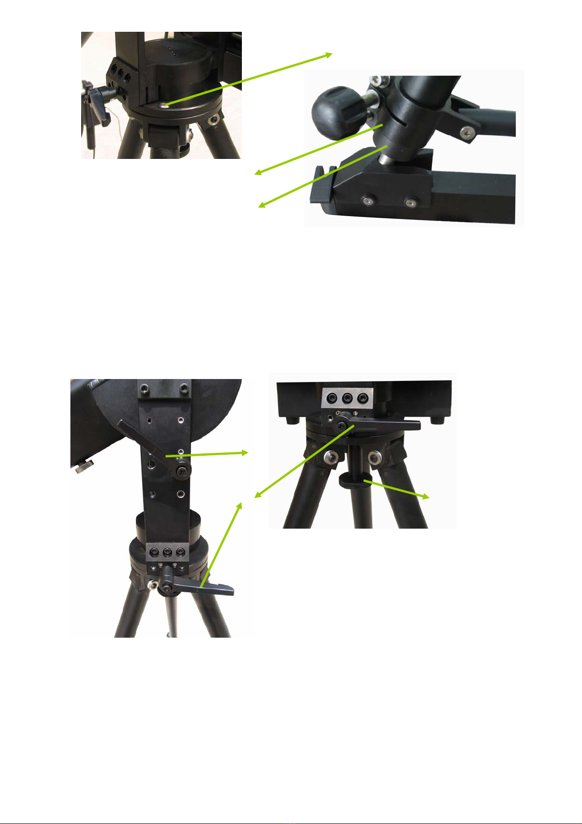
By observing the leveling bubble (Figure 5), one can know if the tripod is horizontally leveled. If
tripod is not horizontally leveled, please adjust the height of tripod to reach level.
To adjust height of tripod, please loosen the knob of locking sleeve (Figure 3) and the inner tube
can be lengthened. After making sure the feet are prolonged to the proper length, tighten the
locking bolt. Loosen the knob of protective sleeve (Figure 3), put the protective sleeve upward to
the highest position and then tighten the knob. The purpose of protective sleeve is to prevent the
outer tube sliding down.
Locking sleeve of tripod
Protective sleeve of tripod
Figure 5
Figure 6
Leveling bubble
3. Central pivot section
Central pivot section should be installed on the tripod and allow the crane arm to swivel horizontally.
As shown in Figure 7, please put the central pivot section on tripod and tighten it with locking knob
(Figure 8).
Attention: To avoid any possible accident may occur, please lock the crane with tilt & pan locking
levers if the crane left unattended.
A
C
B
Figure 8
A. Tilt locking lever
B. Pan locking lever
C. Locking knob of central pivot section
Figure 7
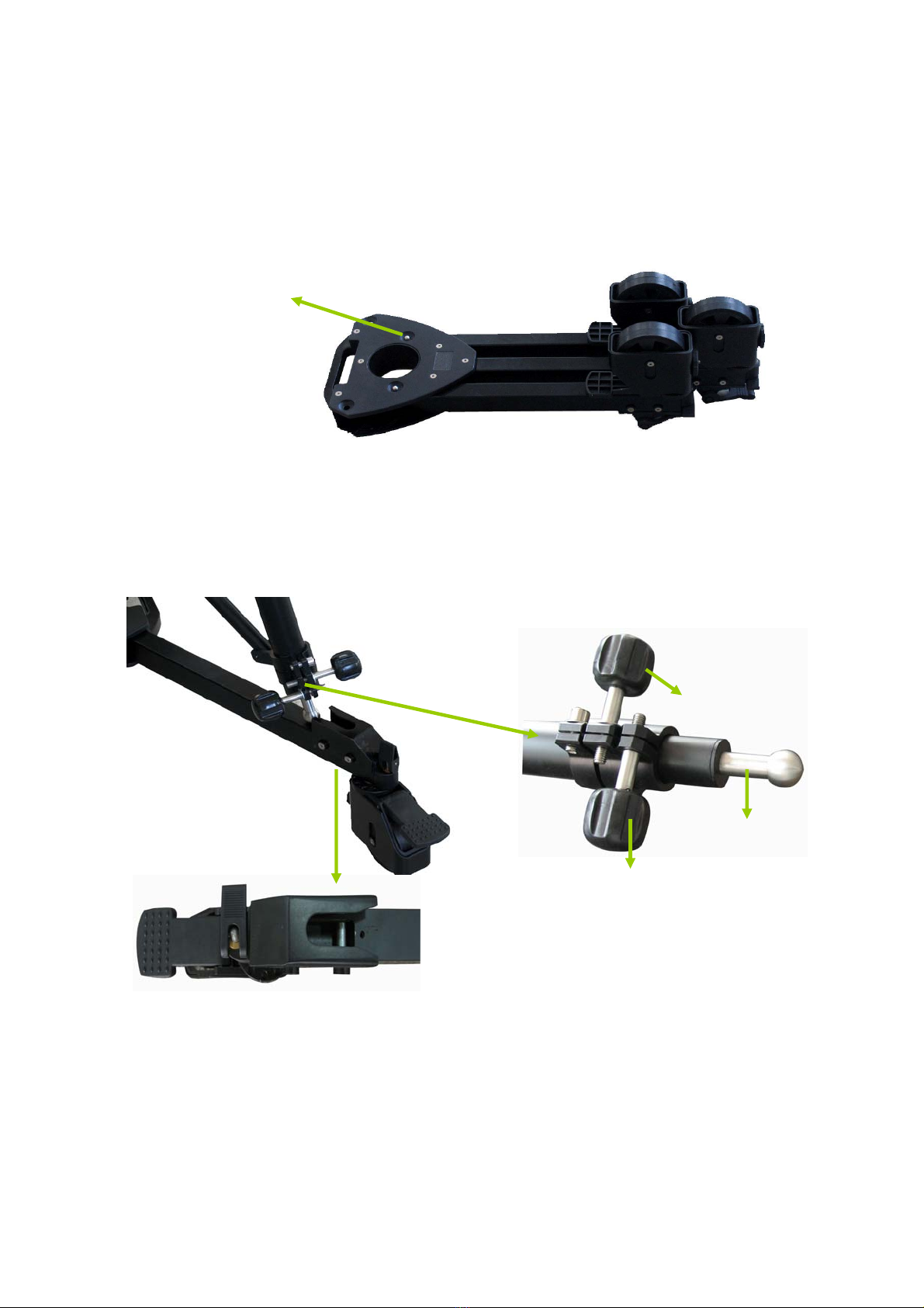
4. Arm
The arm is formed by 5 tubes. The tubes are numbered from the end of counterweight rod. The
installation of the arm shall start from the section 2 tube which has been already mounted on the
central pivot section since the product was completed. The section 5 tube is the one which has the
mounting plate at one end (Figure 10).
5
Other arms are connected with each other by the way shown from Figure 9-1 to Figure 9-2, and use
inner-hexagon spanner to tighten nut and tighten the knob under the tube as well.

Figure 9-2
Figure 9-1
6
Figure 9-3
Figure 9-3
Attention: The right mount counterweight should be mounted after installation of all arm is
completed to avoid any falling down of crane arm.
5. Camera and remote head
To install the remote head, simply plug the remote head onto the mounting frame, and turn locking
lever to tighten it. (Figure 10)
Remote head Mounting frame
Leveling bubble Locking lever
Figure 10
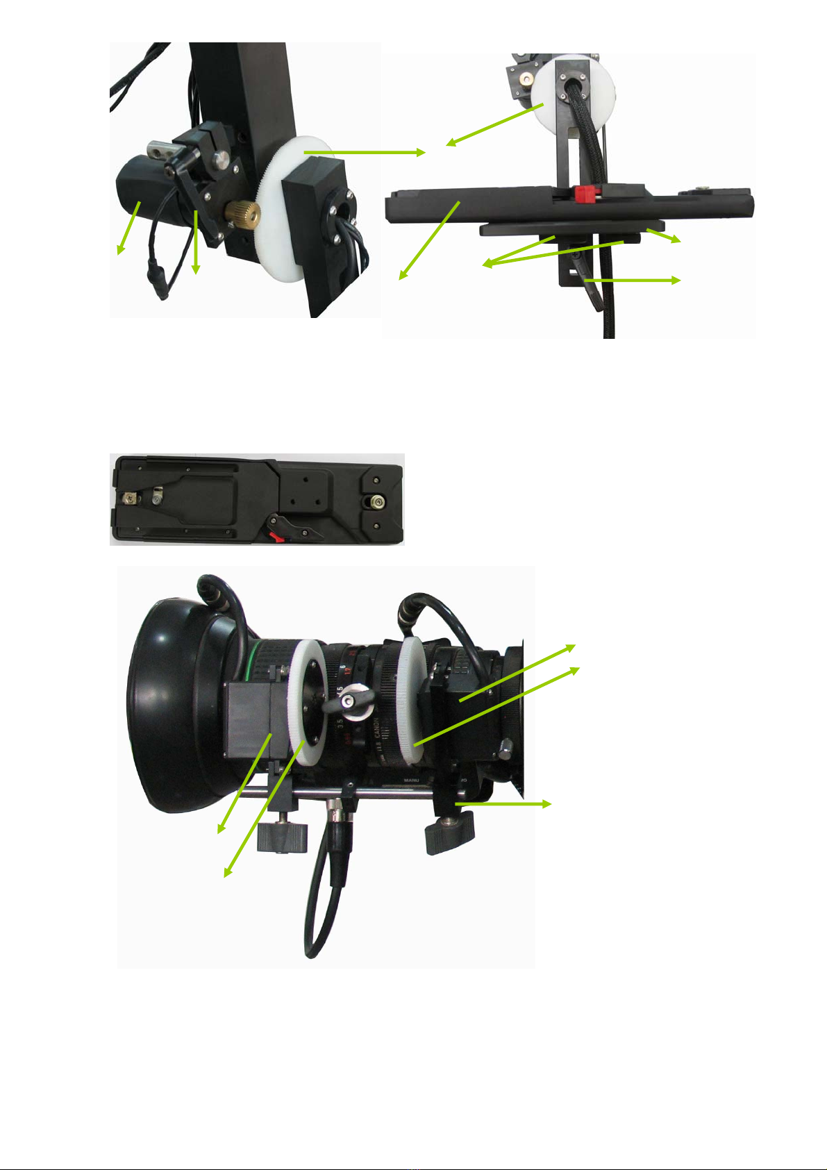
Balance should be adjusted after the camera is installed. If camera uses battery to supply power,
the battery should be installed before adjusting balance. First of all, release the gear of tilt motor;
put the DV camera on the camera plate, use the screw to fix it. Then adjust the positions of the plate
backward or forward according to which way the camera turns, adjust balancing frame upward or
downward according to which way the camera turns, and repeatedly adjust the positions of plate
and balancing frame to ensure the camera doesn’t move anymore when turning to any position.
B
F
A
D
C
G E
Figure 11-2
Figure 11-1
A. Locking lever for tilt motor E. Locking lever for camera plate
B. Tilt gear F. Camera adaptor
C. Screws G. Tilt motor
D. Camera plate
Figure 11-3
Secced SC-3950 Camera adaptor
Figure 12
Iris motor
Iris gear
Focus motor
Focus gear
Motor frame
As shown in figure 12, install the focus and iris control (lens control motor) on the lens.
7
There are two focus gears available, one is for Canon lens, and another is for Fujinon lens. Select
the gear matching with the lens used and install it on the motor frame. Turn clockwise the
focus-adjusting wheel on the lens to the end, and turn anticlockwise the motor gear to the end.
Engage the two gears and tighten the knob of motor fastening. The IRIS motor can be installed by
the same method.

Due to influence of cables on the camera, it may not move when it reaches any positions. Under
such a situation, influence of such a force should be minimized.
6. Balance steel cable
8
Figure 13-1
Front
Figure 13-2
Locking nut 1
Locking nut 2
Locking nut 3
Cable pressing plate Cable guide
Back
Turnbuckle
Figure 13-3
Figure 14
The balancing steel cable is installed upon the arm to make sure the pan & tilt remote head
maintain level. Connect one end at which there is a turnbuckle with mounting frame, and reach the
state which is demonstrated in Figure 13. Another end is placed on the central pivot section, First of
all, use inner-hexagon spanner to loose all three nut (Figure 12-3) and roll the balancing cable over
the cable guide like the way in Figure 12-1 and get it fixed with cable pressing plate (Figure 12-1)
and tighten the three nuts (Figure 12-3).
After installation of the balancing steel cable, please check if the remote head is vertical to the
ground by observing the leveling bubble (Figure 10). Adjust the turnbuckle and remote head after to
make sure the remote head is level.
7. Tension steel cable
The tension steel cable is used for giving a tension force to the pan & tilt remote head and the
camera, keeping the crane straight, increasing the rigidity of the crane arm, and preventing camera
shaking while swiveling the crane.
The top tension steel cable are hooked with both section 1 and section 5 tubes (Figure 14 and 15).
The supporting rods have to be inserted into the hole and put the cable on the top of rod. And use
the turnbuckle to tighten the cable.

A C
D
B
Figure 17
Figure 15
E
A. Tension cable
B. Hook
C. Tension cable supporting rod
D. Balancing cable
E. Turnbuckle
Figure 16
8. Controlling bar
As shown in Figure 17, to install the controlling bar on the counterweight rod and tighten the locking
knob.
Figure 18
Counterweight discs
Locking lever of controlling bar
Counterweight rod
Controlling bar
9
9. Counterweight
Install the counterweight (optional) on counterweight rod as shown in Figure 17, and adjust the
weight to enable the crane to keep balance.
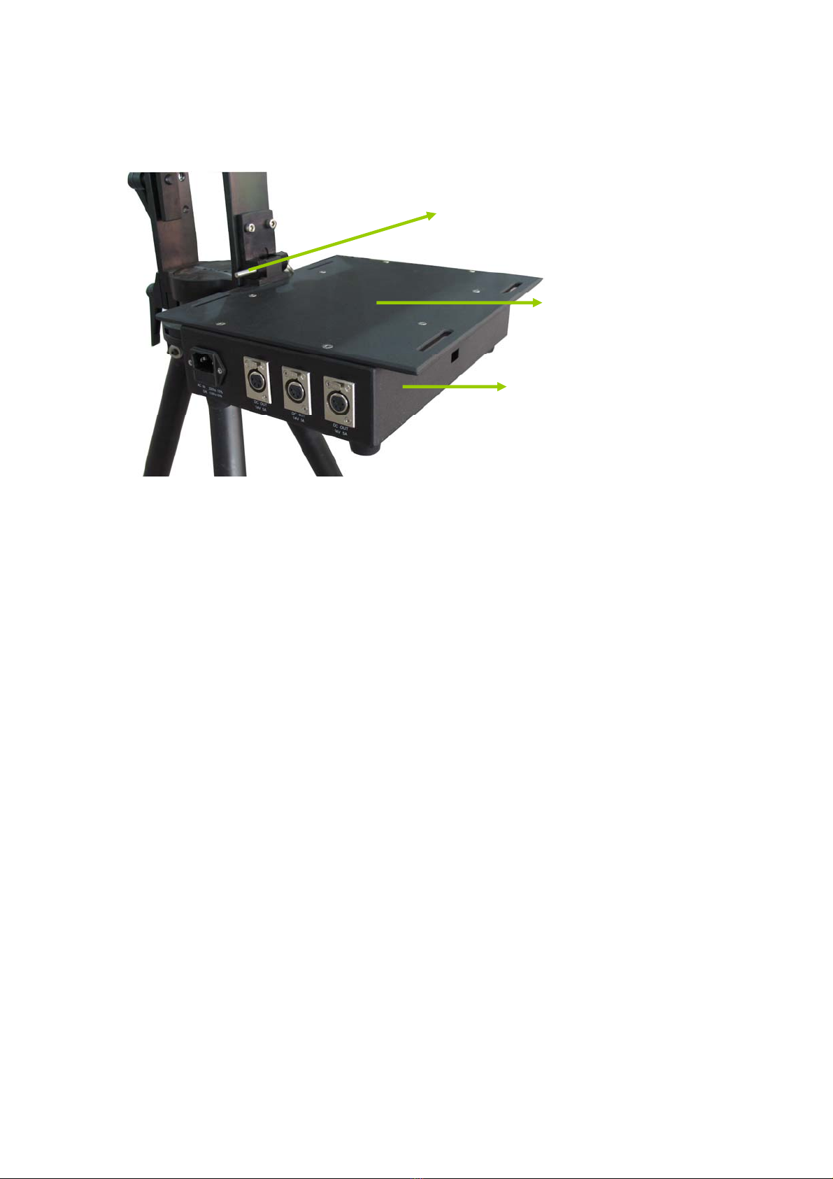
10. Power supply box
Fixing pin
Supporting plate for monitor
Power supply box
Figure 19
.
The power supply box is for supplying the power to the camera, remote head, controlling bar and
monitor. There is two way to get power input, one is the AC 220V or 110V input and another one is
the A–mounting interface under power supply box. To install power supply box, simply plug in the
pin to fix it.
Attention: Operators can change the A-mount interface into V-mount interface by simply taking
down A-mount interface, put on a V-mount plate and tighten the nuts.
Wire Connection
1. Remote head controlling bar, as in Figure 19, insert crane cable, power cable and controlling
bar cable (connecting with camera controlling bar) into the corresponding sockets. (The
sockets for power supply cable and crane cable are on the left-hand side of remote head
controlling bar. The socket for controlling bar cable is on the back of remote head controlling
bar.)
2. Camera controlling bar, insert the controlling bar cable into socket (Figure 20) on back of the
camera controlling bar (Figure 19), which is connected with remote head controlling bar.
3. Remote head, insert the plugs of crane cable into the tilt and pan motors respectively. The plug
with long cable is for tilt motor, and the plug with short cable is for pan motor.
4. Connect the remote head controlling bar with lens control box by using crane cable. Smaller
plug of crane cable is connected with lens control box. Connect the lens control box with
camera lens, by using lens control cable. Three plugs are for ‘ZOOM’, ‘FOCUS’, and ‘IRIS’
respectively, as shown in Figure 22.
5. Monitor: insert video cable into AV output socket of camera, and another end (with yellow sign)
is connected with monitor.
10
6. Using the bounding strap to fix the crane cable with crane arm to avoid any disturbance caused
by cable while in operation.

Controlling bar cable
Integrated controlling bar
Socket
Power supply cable
Figure 20
Figure 21
Remote head controlling bar
Crane cable
Lens control box
For ‘FOCUS’ control
For ‘IRIS’ control
Lens control cable
For ‘ZOOM’ control
Figure 22
11

12
For remote head controlling bar
Crane Cable
Connected For pan motor
For tilt motor
For ‘ZOOM’ control
Connected
Lens control box
Figure 23
Lens control cable
For ‘FOCUS’ and ‘IRIS’ control
Operation
The panels of two controlling bars are shown as follows.
1. Control of remote head
There is a joystick on the remote head controlling bar to control panning and tilting of remote head,
meanwhile there are also some knobs and switches on this controlling bar. ‘SPEED’ controls the
speed of rotation of remote head, ‘CENTER’ can control the remote head rotate automatically as
the speed which is set up with ‘SPEED’ control knob, and ‘DAMP’ is for adjusting the damping of the
remote head. When the damp is small, the pan & tilt head can quickly starts and stops. When the
damp is large, the start and stop of the pan & tilt head have the obvious delay.
2. Control of camera
In Figure 24, the lever labeled with “T” and “W” is used for controlling the zoom of lens, the
“DIRECT” switch is used to change the control direction. “RATE” switch is used to control speed.
The knob under the camera controlling bar is used for adjusting focus (Figure 25). The “DIRECT”

switch is used for changing direction of ‘FOCUS’. The knob above the lens control bar is used for
adjusting Iris. CON/FUJI switch is for switching the control between Canon lens and Fujinon lens.
VCR is to start recording.
Figure 24
Camera controlling barRemote head controlling bar
Figure 25
‘FOCUS’ controlling knob
Back of camera controlling bar
13

14
Specifications and Technical Data
Length 6m
1.64m (including dolly)
Height of central axis 1.45m (excluding dolly)
60°(including dolly)
Elevation angle 50°(excluding dolly)
Rotation radius of pan & tilt head 4.34m
Highest point of pan & tilt head 5.6m
Payload of pan & tilt head 10kg
Horizontal: Unlimited
Rotation angle of pan & tilt head Vertical: ±1800
Horizontal: 10 rounds/min.
Fastest speed of pan & tilt head Vertical: 10 rounds/min.
Line: AC100~240V
Power input AC adaptor: DC 12V 5A
Case 1: 600×450×220
Size of packing case (L x W x H mm) Case 2: 1330×390×390
Case 1: 14.5kg
Case 2: 52kg
Gross weight (Kg)
Total weight: 66.5Kg

15
Packing List
No.1 Case
Number Name Quantity Remark
1 Remote head 1 With pan and tilt motors
2 Remote head controlling bar 1
3 Camera controlling bar 1
4 Crane Cable 1
5 Power cable for controlling bar 1
6 Controlling bar cable 1
7 Video cable 1
8 Power cable for camera 1
9 Power cable for power supply box 1
10 Power cable for monitor 1
11 Bounding strap for monitor 2
12 Lens control cable 1
13 Power supply cable 1
14 Canon/Fujinon lens conversion cable 1
15 Iris & Focus motor 2
16 Mounting frame for Iris & Focus motor 1
17 Iris & Focus gears for Fujinon lens 2
18 Bounding straps 5
19 1/4” for Camera adaptor 1
20 3/8” for Camera adaptor 1
21 Screw for tripod 1
22 Screw for tube 1
23 8-10mm spanner 1
24 12-14 mm spanner 1
25 Inner-hexagon spanner 1
No.2 Case
Number Name Quantity Remark
1 Section 1 tube 1 With bounding strap
2 Section 2 tube 1 With central pivot section
3 Section 3 tube 1
4 Section 4 tube 1
5 Section 5 tube 1 With mounting plate
6 Tripod 1
7 Dolly 1
8 Tension steel cable 2
9 Balance steel cable 1
10 Supporting rod 2 With two knobs
11 Counterweight rod 1
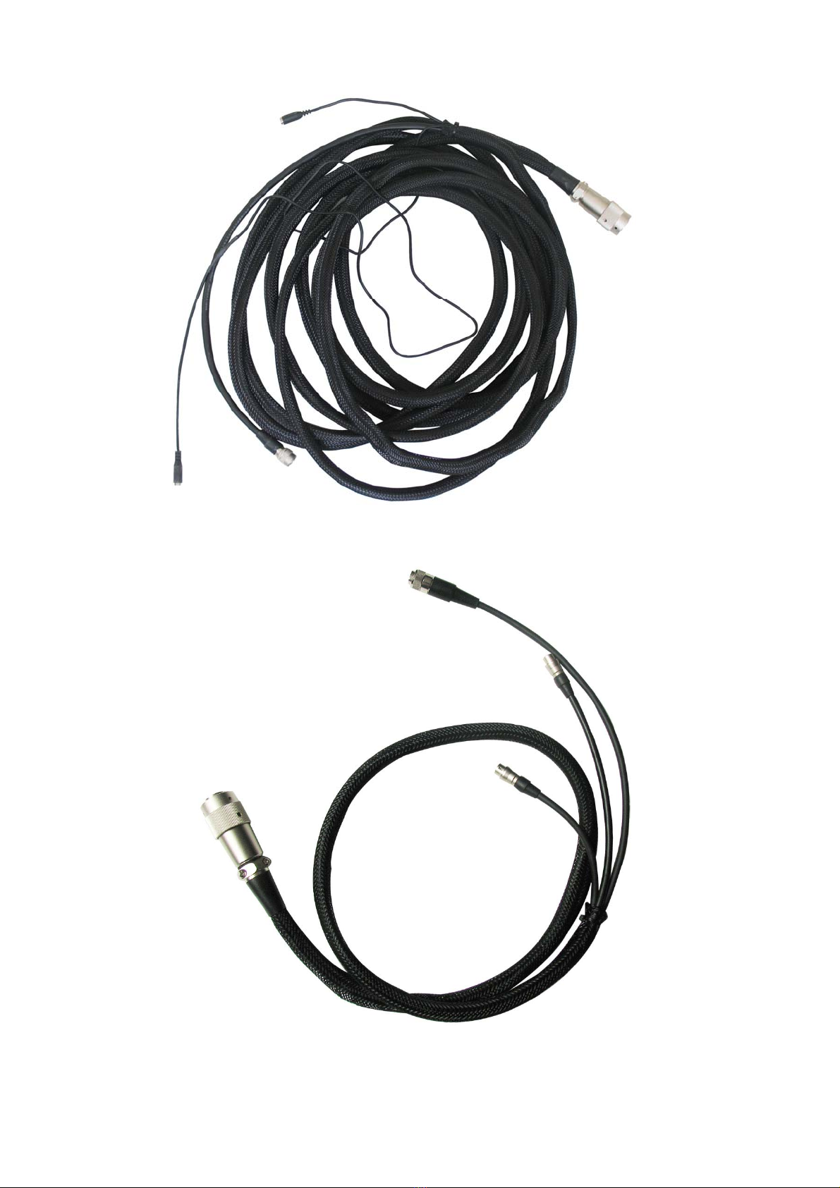
Appendix
Crane Cable
Lens control cable
16

Controlling bar cable
Video Cable
17
Table of contents


