Seco Group NT-2 User manual

UTILITY TRAILER NT-2
HÄNGER
NÁVĚS
EN User’s manual
DE Bedienungsanleitung
CZ Návod k použití
2010
Seco GROUP a. s.
Jungmannova 11
506 48 Jičín
ČESKÁ REPUBLIKA

2
INTRODUCTION
Dear customer,
Thank you for purchasing this accessory from Seco GROUP a.s., a company renowned both in Europe
and internationally as a manufacturer of quality machines and accessories for the maintenance of grass
areas.
This user‘s manual includes instructions for the safe assembly, operation and maintenance of your
accessory.
Do not assemble or use the accessory until you have thoroughly read all instructions,
restrictions and recommendations contained in this user‘s manual.
Keep the user's manual for future use.
If anything is unclear or you have questions, do not hesitate to contact one of our more that 100
authorised, professionally-equipped service centres located all over Europe, where trained and tested
experts will be ready to assist you.
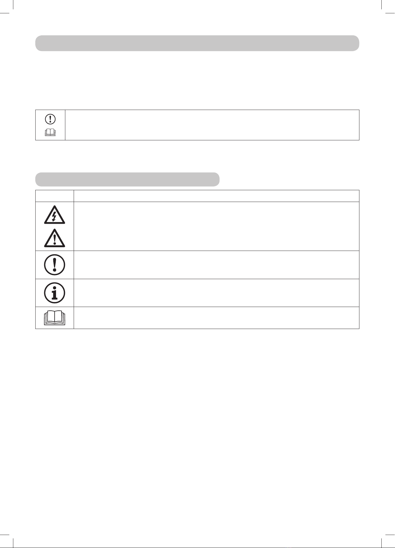
Symbols used in this user’s manual
SYMBOL MEANING
These symbols, together with the word “ATTENTION” or “WARNING”, inform you about
things that may damage your accessory and/or cause serious injury to the user.
This symbol indicates an important instruction, property, procedure or issue, which you
need to be aware of and adhere to during assembly, operation and maintenance of the
accessory.
This symbol indicates useful information relating to the accessory.
This symbol is a reference to a chapter in this or another user's manual and is always
shown together with the number of the chapter to which it refers.

3
1. UNPACKING AND INSPECTING THE CONTENTS
The NT-2 Lawnmower Utility Trailer is supplied wrapped in a protective plastic sheet. For transportation
reasons some of its parts have been dismounted and need to be assembled prior to use ( 6).
Visually inspect immediately after delivery that the packed utility trailer has not been
damaged. If you find any damage or have any doubts, please inform the carrier. In the case
of an irregularity do not unpack the utility trailer and immediately report the discrepancy to
the supplier. If the complaint is not lodged in time, no potential demands can be claimed.
After removing the packaging reinspect all the parts for damage that may have occurred during transport.
Included contents:
[A] - Body
[B] - Trailer hitch
[C] - Axle assembly
[D] - Support member
[E] - User‘s manual, bag with fastening
material, axle holders
[F] - Tyres with roller bearings
1.1 Disposal of packaging
After unpacking the accessory ensure that the packaging material is properly
disposed of or recycled. The disposal must conform to relevant waste disposal laws
valid in the user's country.
Disposal may be performed by a specialised company.
4
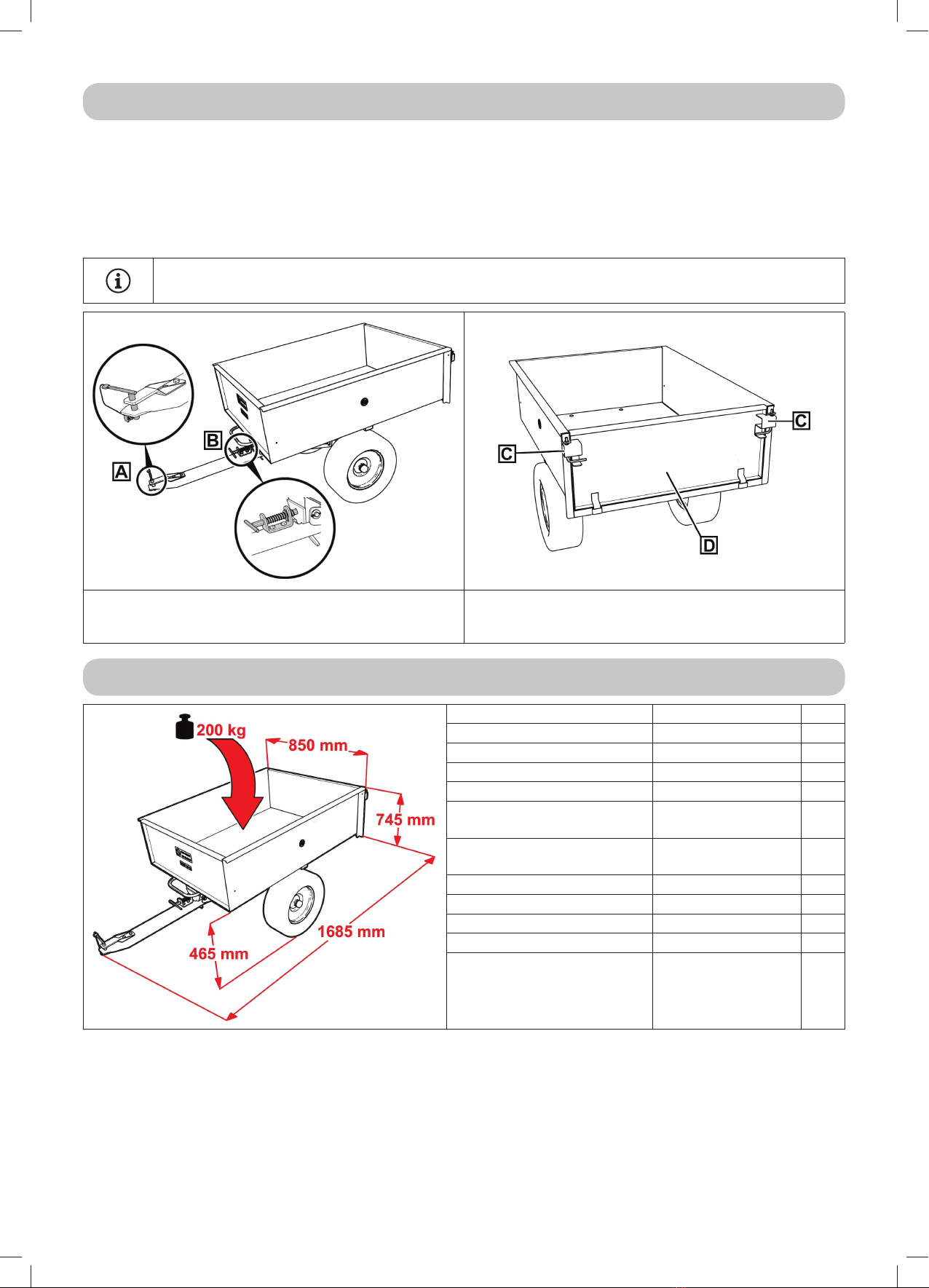
2. DESCRIPTION AND USE
• This trailer is a great helper for transporting various types of loads, e.g. grass clippings, bark, building
materials or firewood. The tyre tread pattern ensures that your lawn is protected.
• The trailer body has rigid front and side walls. The rear wall is removable. The entire trailer can be
easily tipped at an angle of 46°.
• The trailer can be coupled to all tractor models from SECO. It is connected to the hitch on the rear
plate of the tractor.
Starjet models have a hitch included in the price of the machine. To couple the trailer to a
Crossjet model you need to purchase a hitch.
[A] – Coupler
[B] – Tipping mechanism
[C] – Rear latches
[D] – Removable rear wall
3. TECHNICAL SPECIFICATIONS
Height 745 mm
Width 850 mm
Total length 1,685 mm
Total weight 195 Kg
Load capacity 200 Kg
Loading area dimensions
(L x W x H) 1050 × 770 × 300 mm
Height of the loading area
from the ground 465 mm
Wheel gauge 684 mm
Clearance 175 mm
Wheel dimensions 16 × 6.50 - 8NHS
Tyre pressure 0.8 - 1.4 MPa
Wheel bearings Roller -

5
4. SAFETY INSTRUCTIONS FOR PROPER USE
4.1 General safety instructions
! Adhere to all safety instructions in the user‘s manual for the lawnmower to which the trailer will be
connected.
! Before first connecting the trailer make sure that you fully understand how it is operated.
! Remove all defects before using. Before working with the accessory, thoroughly inspect that the wheels
are well mounted, check that the body is secured, bolt connections are pulled tight, the tyre pressure
is correct and that the rear wall is locked in place.
! It is not permitted to perform any technical modifications to the trailer without the manufacturer‘s
written consent. Unauthorised modifications may lead to hazardous work safety conditions and void
the warranty.
! It is forbidden to use the trailer on roads.
4.2 During use
! The trailer must not be used for work on slopes that have an incline greater than 10°.
! It is forbidden to transport people on trailer.
! The maximum load capacity of the trailer must not be exceeded.
! The trailer must be properly coupled.
! It is forbidden to tow the trailer if the body is tilted out and not secured in place. As soon as you tip out
the load, immediately secure the trailer in the correct position.
! When towing the trailer do not exceed the recommended speed (max. 2 km/hour). Pay increased
attention when riding on a slope, reversing and turning.
! Only perform maintenance or repairs with the lawnmower motor turned off.
4.3 After finishing work
! Always maintain the trailer clean and in good technical condition.
! Regularly inspect the bolts, nuts and other fastening elements and ensure that they are securely
tightened.
! Regularly inspect all components and if necessary replace those that need to be replaced based on
the manufacturer‘s recommendations. If you have any doubts about the condition or function of a
component, please contact a professional service centre.

6
5. LABELS USED ON THE TRAILER
5.1 Product identification label
[A] – Model number
[B] – Serial number
[C] – Year of manufacture
[D] – Weight
[E] – Name of manufacturer
[F] – Logo of manufacturer
[G] – Country of origin
[H] – CE marking
[I] – Declaration of conformity with EU regulations
5.2 Safety labels and their meanings
Label indicating that it is forbidden to transport people on the
trailer
Label indicating the load capacity of the trailer
ATTENTION: It is strictly forbidden to remove or damage labels and symbols attached
to the accessory. In the event of damage or illegibility of the label, please contact the
supplier or manufacturer and request a replacement.

7
6. ASSEMBLING THE TRAILER
For transportation reasons the trailer is delivered disassembled and it is necessary to assemble it.
Proceed as follows:
6-1
Insert pins into the abutments [B] on the underside of the body and slide the mounting
brackets [A] on to them.
6-2
Bolt the mounting brackets [A] to the axle assembly [B] using 4 bolts and fasten using nuts.
Do not fully tighten the nuts yet.
6-3
Bolt the trailer hitch [A] to the axle assembly [B] using 4 bolts and fasten using nuts. Then
tighten the nuts on the mounting brackets from the previous step.
8
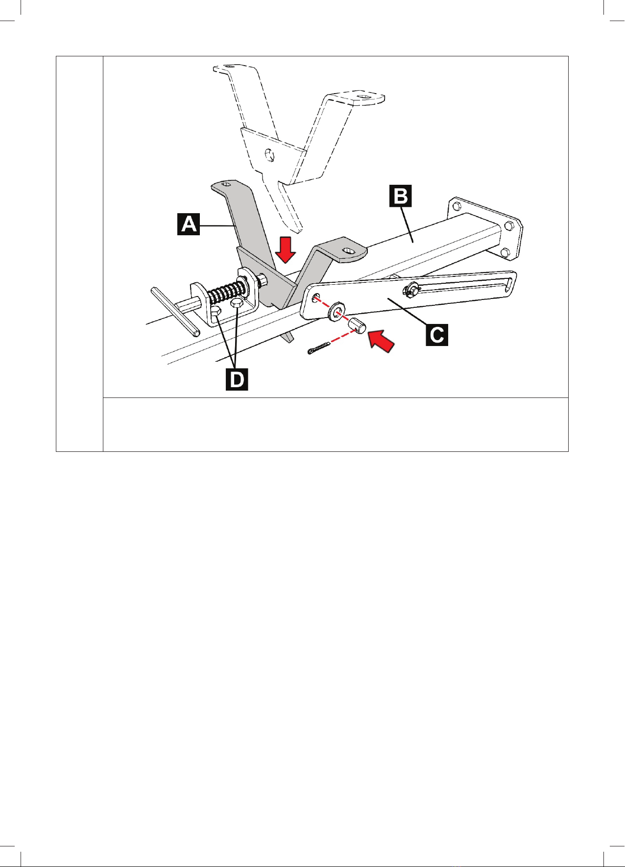
6-4
Attach the support member [A] to the trailer hitch [B]. To help find the correct position of
the pins and the support member, the bolts [D] are loose. After finding the correct position,
tighten them. Then attach the draw bar [C] to the support member using a washer, hitch
pin and an R-clip.

9
6-5
Turn the body upside down and place it on a suitable underlay (protective plastic sheet,
paper, etc.) to prevent the coat from scratching. Connect the support member of the trailer
hitch [A] to the body using two bolts and nuts.
6-6
First apply lubricating grease to the axle shaft [A] and then gradually slide on the wheel,
washers [B], retainer ring [C] and finally the cover [D].
To complete the assembly, tighten all bolt connections and inflate the tyres to the prescribed pressure.
The trailer is now ready for use.

10
7. USING THE TRAILER
7.1 Coupling to the lawnmower
The trailer is coupled to the hitch on the rear plate on the lawnmower. Proceed as follows:
- Pull the R-clip [C] out of the hitch pin [B].
- Insert the hitch pin into the hole on the hitch [A] of the lawnmower.
- Reinsert the cotter pin.
If the rear hitch is not a part of the lawnmower, it is necessary to purchase it separately. For
further information, please contact the technical department at SECO a.s.
7.2 Removing the rear wall
Turn both hinges away
from the bracket.
Push both hinges
downwards and secure
them in place by turning
them under the bracket.
Tilt out and remove the rear wall away from
the trailer body.

11
7.3 Tipping the entire trailer
Slide the hitch pin out of the support member. Tilt the entire trailer to tip out the load.
It is forbidden to tow the trailer if the body is tilted out and not secured in place. As soon as
you tip out the load, immediately secure the trailer body in the correct position.
8. MAINTENANCE
8.1 Maintenance after work
- After every work session remove all dirt (e.g. bits of grass and other transported material) from
the trailer.
While cleaning use protective gloves.
8.2 Regular maintenance
- Regularly inspect all bolt connections and tighten them if necessary.
- Regularly check the tyre pressure. The tyre pressure must be in the range from 0.8 to 1.4 MPa and the
difference between the pressures of the individual tyres may not exceed 12%.
- After every 25 hours of operation and prior to the start of the season, grease the wheel shafts with
suitable lubricating grease.
9. ADDITIONAL ACCESSORIES AND SPARE PARTS
For further information about additional accessories and spare parts and their operation, please contact
our technical department.
10. STORAGE
At the end of the season or if you will not be using the trailer for more than 30 days, it is appropriate to
prepare it for storage as soon as possible. Prepare it as follows:
Replace defective or worn out parts and tighten loose connections. Clean the trailer thoroughly and wash
it. Lubricate the wheel shafts.
Store the trailer covered in a clean and dry environment.

12
11. PUTTING OUT OF OPERATION AND DISPOSAL
Before disposing of the accessory make it unusable. Even products past their lifetime contain raw
materials, which can be recycled. Hand them over to a recycling collection point. It is recommended to
have the accessory disposed of by a specialised company.
When disposing of the accessory on your own, it is necessary to adhere to relevant national waste
disposal regulations.
12. WARRANTY
The warranty period is 24 months. When replacing any part, or due to a complaint/claim, the warranty
for this part is valid for 6 months from the date of replacement, however for a minimum of the warranty
period of the entire machine. In the case of warranty repairs, the warranty is extended by the duration
of the repair.
The manufacturer is obliged to guarantee that the product has the characteristics and parameters
as stated by the manufacturer for the entire duration of the warranty period. The manufacturer is
not responsible for defects on the product caused by wear and tear, incorrect storage, unprofessional
maintenance, tampering with the accessory, accidents and for use in contradiction with the user‘s
manual.
The Seco GROUP a.s. is constantly working on the development and improvement of all the
machines and accessories it manufactures. Therefore, there may be discrepancies between
the text and images in this user's manual and the actual product. No claims can be deduced
from this.
Printing, duplication, publication and translation (even in part) must not be performed without
the written consent of Seco GROUP. The manufacturer reserves the right to change technical
parameters of the product, without prior customer notification.

13
ES STATEMENT OF COMPLIANCE
persuant to: Act No. 22/1997 Coll.
A. We: Seco GROUP a.s., Šaldova 408/30, Prague 8
branch: 02 Jičín, Jungmannova 11
Corporate number: 60193450
We issue the following statement:
B. Mechanical equipment
- name: Utility Trailer
- model: NT-2
- serial number:
Description:
The NT-2 is a utility trailer for lawnmower tractors AJ102, AG122 and AC92. The maximum load capacity is
200kg. It consists of the self-bearing dump body with a removable rear wall and an axle with 2 wheels. The
axle assembly comes together with a coupling trailer hitch. The utility trailer is not equipped with brakes.
C. Legislation forming the basis for assessment of compliance:
Act. No. 22/1997 Coll.
D. Assessment of compliance was performed according to the designated procedure in:
Government directive No. 176/2008, §5, para. 2
E. We confirm that:
- this mechanical equipment defined above complies with the requirements in the above technical regulations
and under normal operating conditions it is safe.
- measures have been taken to ensure the compliance of all products introduced to the market with the
technical documentation and the requirements contained in technical regulations.
Technical documentation in the extent as per attachment V is held by the manufacturer at:
Seco GROUP
odštěpný závod 02 AGS
Jungmannova 11
506 48 Jičín
In Jičín, on 1.10.2010 Ing. Jiří Pávek
Member of the Board of Directors
14
VORWORT
Sehr geehrter Kunde,
vielen Dank, dass Sie sich für ein Produkt der Firma Seco GROUP a.s. entschieden haben. Unser
Unternehmen ist europa- und weltweit als Hersteller von hochwertigen Maschinen und Zubehör zur
Pflege von Gras- und Rasenflächen anerkannt.
Diese Anleitung enthält wichtige Hinweise für die sichere Installation, den Betrieb und die Wartung Ihres
Zubehörs.
Bevor Sie das Produkt installieren und benutzen, lesen Sie alle Hinweise, Verbote und
Empfehlungen gründlich durch, die in dieser Anleitung aufgeführt sind.
Bewahren Sie die Anleitung zur späteren Verwendung gut auf.
Bei Fragen und Unklarheiten wenden Sie sich an eine unserer über 100 gut ausgestatteten autorisierten
Servicewerkstätten in ganz Europa. Dort stehen Ihnen geschulte und vom Hersteller geprüfte Techniker
zur Verfügung.
In der Anleitung verwendete Symbole
SYMBOL BEDEUTUNG
Diese Symbole in Verbindung mit dem Wort „HINWEIS“ oder „WARNUNG“, weisen
auf Sachverhalte hin, die zu einer Beschädigung des Zubehörs und/oder zu ernsthaften
Verletzungen des Anwenders führen können.
Dieses Symbol weist auf wichtige Anweisungen, Eigenschaften, Vorgehensweisen oder
Sachverhalte hin, die während der Installation, Benutzung und Wartung des Zubehörs
beachtet oder eingehalten werden müssen.
Dieses Symbol weist auf nützliche Informationen zum Zubehör hin.
Dieses Symbol verweist auf ein Kapitel in dieser oder einer anderen Anleitung und steht
jeweils zusammen mit der Nummer des Kapitels, auf das es sich bezieht.

15
1. AUSPACKEN UND KONTROLLE DER LIEFERUNG
Der Hänger NT-2 wird in Schutzfolie verpackt geliefert. Zum besseren Transport sind einige Teile
abmontiert und müssen vor der Inbetriebnahme montiert werden ( 6).
Führen Sie sofort nach Erhalt eine Sichtkontrolle auf Beschädigungen am verpackten Hänger
durch. Im Fall einer Beschädigung oder irgendwelcher Zweifel ziehen Sie den Spediteur
hinzu. Packen Sie den Hänger im Fall einer Uneinigkeit nicht aus und melden Sie den Konflikt
sofort dem Lieferanten. Wird eine eventuelle Reklamation nicht rechtzeitig geltend gemacht,
können mögliche Ansprüche nicht berücksichtigt werden.
Kontrollieren Sie nach der Entfernung der Verpackung alle Teile, ob sie nicht während des Transports
beschädigt wurden.
Lieferumfang:
[A] - Mulde
[B] - Deichsel
[C] - Achse
[D] - Stütze
[E] - Bedienungsanleitung, Beutel mit
Verbindungsmaterial, Achsenhalter
[F] - Reifen mit Lagern
1.1 Entsorgung der Verpackungen
Achten Sie nach dem Auspacken des Produktes auf die ordnungsgemäße Entsorgung
und Wiederverwertung des Verpackungsmaterials. Entsorgen Sie die Verpackung
nach den Vorschriften des im Land der Nutzung geltenden Abfallgesetzes.
Die Entsorgung kann auch einer Spezialfirma anvertraut werden.

16
2. BESCHREIBUNG UND BENUTZUNG
• Der Hänger ist ein ausgezeichneter Helfer bei dem Transport verschiedener Arten von Ladung wie zum
Beispiel gemähtes Gras, Rinde, Baumaterial oder Brennholz. Das Profil der Reifen gewährleistet einen
Schutz Ihres Rasen.
• Die Hängermulde hat feste Seitenwände und eine feste vordere Stirnwand. Die hintere Stirnwand ist
abnehmbar. Der gesamte Hänger ist einfach klippbar, im Winkel von ungefähr 46°.
• Der Hänger lässt sich an alle Traktormodelle der Firma SECO ankoppeln. Er wird an die Aufhängung an
der rückwärtigen Platte am Traktor angekoppelt.
Bei dem Modell Starjet ist die Aufhängung für den Hänger schon im Preis der Maschine
enthalten. Für die Ankopplung des Hängers zum Modell Crossjet müssen Sie eine Aufhängung
nachkaufen.
[A] – Kopplungshaken
[B] – Kippmechanismus
[C] – Hintere Sicherung
[D] – Hintere abnehmbare Stirnwand
3. TECHNISCHE DATEN
Höhe 745 mm
Breite 850 mm
Gesamtlänge 1.685 mm
Gesamtgewicht 195 kg
Tragfähigkeit 200 kg
Abmessungen der
Ladefläche (L x B x H) 1.050 × 770 × 300 mm
Höhe der Ladefläche vom
Boden 465 mm
Radabstand 684 mm
Lichte Höhe 175 mm
Radabmessung 16 × 6,50 - 8NHS
Reifendruck 0,8 - 1,4 MPa
Radlager Wälzlager -

17
4. SICHERHEITSHINWEISE FÜR DIE SACHGEMÄSSE
ANWENDUNG
4.1 Allgemeine Sicherheitshinweise
! Beachten Sie alle Sicherheitshinweise in der Bedienungsanleitung des Rasentraktors, an den der
Hänger angekoppelt wird.
! Lesen Sie vor der ersten Benutzung des Hängers die Bedienungsanleitung gründlich durch.
! Stellen Sie vor der Arbeit mit dem Hänger alle Mängel ab. Kontrollieren Sie vor Beginn der Arbeit
sorgfältig insbesondere die Befestigung der Räder, die Sicherung der Mulde, den festen Sitz von
Schraubenverbindungen, den Luftdruck in den Reifen und die Sicherung der hinteren Stirnwand.
! Am Hänger dürfen ohne schriftliche Zustimmung seines Herstellers keine technischen Änderungen
vorgenommen werden. Unberechtigte Änderungen gefährden die Arbeitssicherheit und können zum
Verlust der Gewährleistung führen.
! Es ist verboten, mit dem Hänger über öffentliche Straßen zu fahren.
4.2 Während der Benutzung
! Der Hänger darf nicht zur Arbeit an Hanglagen mit einer Neigung von mehr als 10° eingesetzt werden.
! Es ist verboten, auf dem Hänger Personen zu transportieren.
! Der Hänger darf nicht über seine maximale Tragfähigkeit hinaus belastet werden.
! Die Ladung muss ordentlich befestigt sein.
! Es ist verboten, mit dem Hänger zu fahren, wenn die Mulde gekippt und nicht gesichert ist. Sobald Sie
eine Ladung abkippen, sichern Sie sofort den Hänger in der richtigen Position.
! Halten Sie während der fahrt die empfohlene Geschwindigkeit ein (max. 2 km/h). Beachten Sie der
Fahrt an Hängen, beim Zurücksetzen und beim Kurvenfahren eine erhöhte Vorsicht.
! Führen Sie Wartungs- oder Reparaturarbeiten nur bei ausgeschaltetem Motor des Rasenmähers durch.
4.3 Nach Abschluss der Arbeiten
! Halten Sie den Hänger stets sauber und in gutem technischem Zustand.
! Kontrollieren Sie regelmäßig die Schrauben, Muttern und sonstigen Befestigungselemente und achten
Sie darauf, dass sie ordnungsgemäß angezogen sind.
! Kontrollieren Sie regelmäßig alle Komponenten und wechseln Sie bei Bedarf die Teile aus, die laut
Herstellerempfehlung ausgewechselt werden müssen. Kontaktieren Sie in irgendeinem Zweifelsfall
über den Zustand oder die Funktion irgendeiner Komponente den Fachservice.

18
5. AM HÄNGER VERWENDETE SCHILDER
5.1 Typenschild
[A] – Typennummer
[B] – Herstellungsnummer
[C] – Herstellungsjahr
[D] – Gewicht
[E] – Herstellerbezeichnung
[F] – Herstellerlogo
[G] – Herstellungsland
[H] – CE-Zeichen
[I] – EU-Konformitätserklärung
5.2 Sicherheitsschilder und ihre Bedeutung
Das Schild weist auf des Transportverbot von Personen im Hänger
hin
Das Schild führt die Tragfähigkeit des Hängers auf
HINWEIS:Es ist streng verboten, Schilder und Symbole zu entfernen oder zu
beschädigen, die am Zubehör angebracht sind. Bei Beschädigung oder Unlesbarkeit von
Schildern wenden Sie sich an den Lieferanten oder Hersteller und fordern Sie Ersatz an.

19
6. ZUSAMMENBAU DES HÄNGERS
Der Hänger wurde aus Transportgründen nicht montiert geliefert und er muss zusammengebaut werden.
Gehen Sie dabei wie folgt vor:
6-1
Setzen Sie in die Laschen [B] auf der unteren Seite die Bolzen ein und schieben Sie auf sie
die Halter. [A].
6-2
Schrauben Sie die Halter [A] mit 4 Schrauben zur Achse [B] fest und sichern Sie sie mit
Muttern. Ziehen Sie die Muttern noch nicht fest.
6-3
Schrauben Sie die Deichsel [A] an der Achse [B] mit Hilfe von 4 Schrauben fest und sichern
Sie sie mit Muttern. Dann ziehen Sie die Muttern der Halter aus dem vorhergehenden Schritt
fest.

20
6-4
Sichern Sie die Stütze [A] an der Deichsel [B]. Zum Auffinden der richtigen Position des
Bolzens und der Stütze sind die Schrauben [D] gelöst. Ziehen Sie sie nach dem Finden der
Position an. Sichern Sie dann zur Stütze die Stange [C] mit Hilfe von Unterlegscheibe, Bolzen
und Sicherungsring.
Table of contents
Languages:
Popular Utility Vehicle manuals by other brands


Bitelli
Bitelli Pulcino DTV 310S Operating instructions book

GEM
GEM eM 1400 owner's manual

TrailMax
TrailMax T-12-UT manual

Nilfisk-Advance
Nilfisk-Advance CYCLONE 56380676 manual de utilização

American Sportworks
American Sportworks 7151 150cc Owner's manual / parts guide

Oldenbourg group
Oldenbourg group euv-400 Parts and service manual