Global ANV-400 User manual

Tipping Trailer
1
TIPPING TRAILER
ANV-400
Instructions for use

Tipping Trailer
2
Contents
1 Introduction ...................................................................................................................................................................................2
1.1 Note well..............................................................................................................................................................................2
2 Operational safety ..........................................................................................................................................................................3
2.1 Safety regulations .................................................................................................................................................................3
2.2 Safety labels .........................................................................................................................................................................4
3 Basic information............................................................................................................................................................................ 4
3.1 Use of t e device ..................................................................................................................................................................4
3.1.1 Tec nical data .............................................................................................................................................................4
3.2 Description of t e device and its parts.....................................................................................................................................4
4 Operating instructions .....................................................................................................................................................................4
4.1 Device assembly ...................................................................................................................................................................4
4.1.1 Device assembly procedure...........................................................................................................................................4
4.2 Working wit t e device.........................................................................................................................................................5
4.2.1 Connection to t e small tractor......................................................................................................................................5
4.2.2 Before driving .............................................................................................................................................................5
4.2.3 Driving........................................................................................................................................................................5
4.2.4 Tilting t e body and t e rear end ..................................................................................................................................6
5 Maintenance, care, storing...............................................................................................................................................................6
5.1 Lubrication of t e device ........................................................................................................................................................6
5.1.1 Lubrication points ........................................................................................................................................................6
5.1.2 Brake adjustment.........................................................................................................................................................6
5.1.3 Tyres..........................................................................................................................................................................6
5.2 Storing.................................................................................................................................................................................7
5.2.1 Was ing and cleaning t e device................................................................................................................................... 7
5.3 Disposal of packaging and t e device at t e end of its service life ..............................................................................................7
5.4 How to order spare parts .......................................................................................................................................................7
6 Address of t e Supplier ...................................................................................................................................................................7
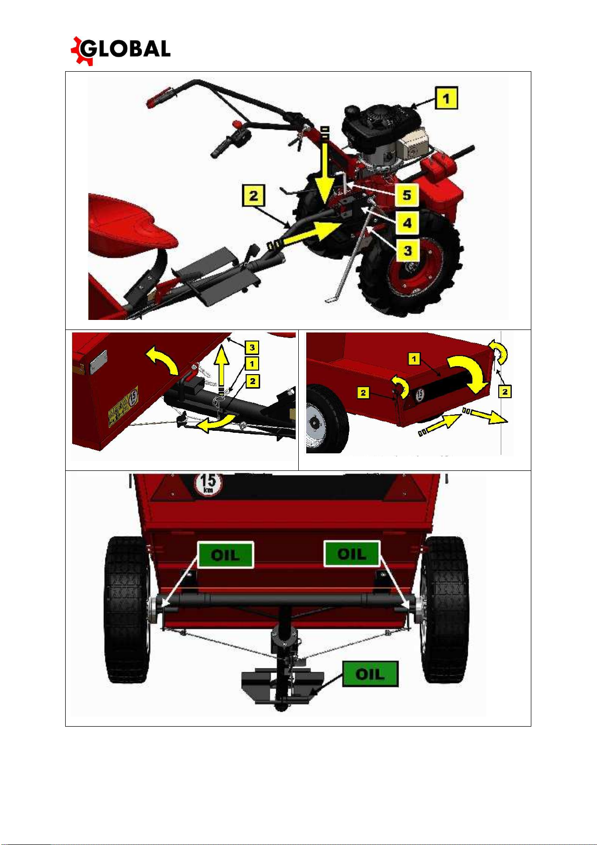
7 Attac ed illustrations.......................................................................................................................................................................8
T e manufacturer reserves t e rig t to implement tec nical c anges and innovations not affecting t e operability and
safety of t e device. T ese c anges may not s ow in t ese Operating Instructions. Typograp ical errors reserved.
1 Introduction
Dear Customer/User!
T ank you for your confidence in purc asing our product. You ave become an owner of a device from t e wide range of
mac inery and tools of t e gardening, farming, small scale agricultural and municipal tec nology system supplieded by
KNIGHTS a.s.
Please read t ese Operating Instructions carefully. If you follow t e instructions contained erein, our product will serve
you reliably for many years.
1.1 Note well
T e user must read through t ese Operating Instructions and follow all device operating instructions in order to prevent
any ealt risks or property damage to t e user or ot er persons.
Safety instructions stated in t is manual do not cover all possible conditions and situations w ic may occur in practice.
Safety factors suc as a reasonable approac , care and caution are not included in t is manual but it is assumed t at eac
person using t e device or doing any maintenance work on it is sufficiently endowed wit t ese.
Only mentally and p ysically fit persons may use t is device. S ould t is device be used commercially, t e owner of t e
device is bound to provide t e operators wit work safety training and instruct t em in operation of t e device and keep
records of suc training. The ow er must also impleme t the so-called categorizatio of work accordi g to
respective atio al legislatio .
If any piece of information contained in t e manual is unclear to you, please contact your dealer or directly t e device
supplier.
Operating instructions provided wit t is device form an integral part of it. T ey must be available at all times, stored at an
accessible place w ere t ey cannot get destroyed. In t e case t e device is sold to anot er person, t e operating instructions
must be anded over to t e new owner. T e manufacturer bears no responsibility for t e risks, azards, accidents or injuries
resulting from operation of t e device, if t e above-mentioned conditions ave not been met.
T e manufacturer bears no responsibility for t e damage caused by unaut orized use, inappropriate operation and for any
damage caused by any modification of t e device wit out t e manufacturer’s approval.
During work it is necessary to follow safety regulations to avoid any injury to yourself or ot er persons present nearby and
to avoid any property damage.
T ese instructions are marked in t e manual by t e following warning symbol:
If you see this symbol i the ma ual, carefully read the stateme t followi g after it!
This i ter atio al safety symbol i dicates importa t i structio s co cer i g safety. If you see this symbol, be
aware that there is a risk of i jury to you or other perso s a d carefully read the stateme t followi g after it.
Table 1 : Symbols

Tipping Trailer
3
2 Operational safety
2.1 Safety regulations
T e combination of t e motor unit wit trailer may only be operated under t e following conditions:
•under reduced visibility: ban on all roads
•under normal visibility:
- operation is pro ibited on primary and secondary roads wit t e exception of perpendicular crossing
- operation is allowed on tertiary roads
Before t e use of t e ANV-400 trailer, it is necessary to perform t e tec nical inspection of t e ve icle, especially:
•securing t e connecting pin to t e tractor
•c eck of t e correct function of t e brakes
•tig tening of t e screws of t e split drawbar, w eels
•tyre pressure
•separate inspection of t e drive unit
T e towing itc connection pin must always be secured by t e cotter.
W en stationary, t e trailer connected wit t e tractor must always be secured by t e andbrake.
Never exceed t e maximum trailer load and t e total weig t of t e ve icle combination. T e trailer must not be overloaded
in excess of its maximum permitted payload (see t e tec nical data table).
W en moving from a slope, always ave t e 1st or 2nd gear engaged and t e w eel latc es in t e locking position.
Monitor t e braking efficiency carefully. If low efficiency is observed, it is necessary to adjust t e brakes immediately.
Be particularly careful especially in steep terrain out of firm roads.
It is forbidden to op on or off t e trailer w ile moving.
It is forbidden to transport people on t e trailer.
To fasten t e bulk materials loaded on t e trailer, use sufficiently strong and tested ropes designed for t at purpose.
Watc out for possible quick tilting of t e body (t e front part of t e body rises upwards) if t e centre of gravity of t e load
is s ifted be ind t e axes of t e inges.
T e maximum climbing ability of t e trailer wit connected tractor is 13 degrees. T e climbing ability means t at t e fully
loaded trailer wit t e tractor can be operated on slopes wit an inclination of 13 degrees.
Do not start t e motor of t e tractor indoors! T e ex aust gases contain poisonous carbon monoxide. In alation may lead
to loss of consciousness or even to deat .
During operation, t e ex aust system of t e motor is eated to a very ig temperature, w ic it maintains for a long time
after switc ing off. T erefore avoid contact wit surrounding objects - t ere is a risk of fire. W en touc ing any ot part, t ere
is a risk of severe burns!
Petrol is an extremely flammable and, under certain circumstances, ig ly explosive substance! Refuelling s all be
performed in a well ventilated area wit t e motor off; open fire must be avoided! Do not smoke! W en refilling petrol, make
sure t at no leak occurs and it is not spilled over t e motor parts! Ot erwise dry t e affected parts or wait until t e petrol
evaporates!
All repairs, adjustment and lubrication of t e device must be performed w en t e device is at a standstill.
C eck regularly t e condition of t e tread pattern and sides of t e tyres.
In case of any crack or bulge, t e trailer must be taken out of operation and t e tyre replaced wit a faultless one.
W en working wit t e device, use sturdy s oes, tig t clot ing and working gloves.

Tipping Trailer
4
2.2 Safety labels
T e user is obliged to keep t e labels on t e device in a legible condition and to replace t em if t ey are damaged.
Positio :
Number:
Descriptio :
Fig. 7 Safety labels – body,
bottom right side
1 - 5
Caution - Before using t e device, read t roug t e operating instructions.
2 - 6
Danger of running over people – Passenger transport pro ibited; people may only be transported on places
designated for t at purpose.
3 - 7
Danger of crus ing - Keep safe distance
4 - 8
Caution - Maximum permitted safe climbing ability
9
Maximum permitted speed
Table 2 : Safety labels
3 Basic information
3.1 Use of the device
T e ANV-400 trailer is designed for t e transport of various materials, objects and tools in combination wit t e GLOBAL
Multipurpose Mini Tractor. T e towing itc is Z-01.
3.1.1 Technical data
Descriptio
U it
Value
Lengt x widt x eig t of t e trailer
mm
2853 x 1337 x 987
Internal dimensions of t e body / eig t of t e loading platform above ground
mm
1330 x 1020 x 296 / 398
W eel track
mm
1179
Weig t
kg
125
Rims / Tyres
−
5.00-12 / 5.00-12
Tyre inflation
kPa
300
Small tractor
type
GLOBAL
Drive unit
type
PJGCV160, PJGCV190, PJXP200
Total lengt of t e combination
mm
3600
W eelbase of t e combination
mm
2290
Max. tec nical / permissible weig t of t e combination (small
tractor+trailer+driver+load)
kg
770
Max. tec nical / permissible weig t per axle
kg
245/245 ; 570/570
Max. load capacity (load only - w/o t e driver 75 kg)
kg
400
Maximum permitted speed of t e combination
km. -1
13
Table 3 : Tech ical details
3.2 Description of the device and its parts
Fig. 1
T e ANV-400 trailer consists of t e c assis 1 and body 2 wit folding and removable end 3 secured by two locking
levers 4 . T e connection to t e c assis is provided by means of swivel inges 5 screwed to t e cross beam of t e axle 6
and by means of t e locking pin 7 in t e front part. T e body suspension enables t e platform to be tilted by approx. 30
degrees backwards. T e body is equipped wit reflectors on t e front end, sideboards and rear end. T e c assis is tubular, self-
supporting, split. T e basis of t e c assis is a longitudinal tube, w ic is split into two alves connected wit screw connection
– drawbar 8 and axle 6 . T e drawbar 8 bears t e seat 9 and closing mec anism 7 for tilting t e body. T e drawbar is
equipped wit t e swinging extension 10 in its front part, by means of w ic t e trailer can be connected to t e small tractor.
T is swinging part enables t e trailer to be tilted transversely relative to t e tractor. T e axle 6 is made of a t ick-walled tube.
Axle pins are on bot sides of t e axle. T e attac ment of t e body 5 is also mounted on t e axle. T e brake support plates
11 wit jaws and t e brake drums 12 in anti-friction bearings are welded on t e pins . T e w eels 13 wit steel plate non-
split rim are attac ed to t e brake drums wit four screws. T e tyres wit t e road pattern are equipped wit t e inner tubes.
In t e front part of t e drawbar 8 t ere are welded t e footrests 14 and t e brake control. T e brakes are mec anical and
t ey are controlled from t e driver's seat by t e foot pedal 15 or by t e andbrake lever 16 located under t e seat.
4 Operating instructions
If the operati g i structio s co tai "left side" or "right side", it is always from the view of the sitti g driver.
4.1 Device assembly
Request u packi g of the device a d trai i g from your dealer as a part of the pre-sale service!
Owi g to the weight of the device, its assembly must be performed by two perso s
4.1.1 Device assembly procedure
T e ANV-400 trailer is delivered unassembled in a cardboard box. During assembly, proceed as follows.
Fig. 2
1. > 1 Use t e four M10x25 screws 1 , four 10.2 spring was ers 2 and four M10 nuts 3 to screw t e central tube
4 to t e axle 5 . Tig ten t e screw connections properly wit a torque of 45 Nm.

Tipping Trailer
5
2. > 2 Turn t e body 6 upside down and lay it on clean flat surface. Unlock and tilt t e body locking lever 7 . Turn
t e assembled c assis so t at t e brake key control levers point upwards and lay t e c assis onto t e body. Use t e
M10x25 screws 8 to screw t e inges 9 to t e body 6 . Tig ten t e screws properly wit a torque of 45 Nm.
3. > 2 Use t e M8x25 screw 11 , t e 8.4 was er 12 and t e nut 13 to screw t e body securing c ain 10 to t e
foot on t e bottom of t e body 6 .
4. > 3 Run t e end of t e brake rope 14 t roug t e ole in t e lever of t e left brake key 15 and secure t e eye
wit t e larger clamp 16 . Run t e ot er end of t e rope t roug t e ole in t e lever of t e rig t brake key 17 .
Again, secure t e eye wit t e larger clamp 16 . During assembly, tig ten t e rope so t at bot brakes are braked
(after several presses of t e brake pedal, t e eyes align and t us t e brakes are released). After t e mounting of t e
rope, t e brake pedal must be inclined from t e vertical plane by no more t an 25° forwards.
5. > 3 Run t e end of t e s orter rope 18 t roug t e ole in t e lever of t e andbrake 19 and secure t e eye
wit t e clamp 20 . Run t e ot er end of t e rope t roug t e oles in t e brake rod yoke 21 and again secure
t e eye wit t e clamp 20 . T e rope s all be mounted on t e lever wit t e brakes released.
Tighte the uts of the cable clamps properly!
After approximately twe tieth braki g, it is ecessary to check a d adjust the fu ctio of both brakes!
6. > 4 Unscrew t e ring 22 from t e central tube 4 , put on t e swinging part of t e drawbar 23 and screw t e
ring 22 back. Tig ten t e screw connection properly wit a torque of 24 Nm.
7. > 5 Use t e M10x25 screws 24 (4 pcs.) to screw t e w eels 25 to t e brake drums 26 . Tig ten t e screws
properly wit a torque of 45 Nm.
8. > 6 Turn t e assembled trailer onto t e w eels. Screw t e spring of t e seat 27 to t e central tube 4 by means
of t e M12x30 screws 28 (2 pcs.), 12.2 spring was ers 29 (2 pcs.) and M12 nuts 30 (2 pcs.). Tig ten t e screw
connections properly wit a torque of 84Nm.
9. > 6 Screw t e seat 31 by means of t e M10x25 screws 32 (4 pcs.) to t e spring of t e seat 27 to t e position
suitable for your p ysique. Tig ten t e screws properly wit a torque of 45 Nm.
4.2 Working with the device
4.2.1 Connection to the small tractor
The towi g hitch co ectio pi must always be secured by the cotter.
Fig. 3 T e trailer s all be connected to t e small tractor by means of t e Z-01 towing itc . T e diameter of t e connection
pin is 16 mm and it must not be replaced wit a no-original model.
1. Move t e w eel latc es of t e tractor to t e manual travel position (see t e manual of t e small tractor or t e gearbox)
2. Reverse to t e trailer 2 to a suitable distance between t e towing itc 4 of t e small tractor 1 and t e swinging part
of t e drawbar.
3. Stabilize t e small tractor 1 by means of t e ON-01 supporting leg 3 . Lift t e trailer by t e swinging part of t e
drawbar and insert t e eye of t e swinging part of t e drawbar between t e feet of t e towing itc so as to centre t e
ole in t e upper foot against t e ole in t e eye of t e swinging part of t e drawbar.
4. Insert t e pin 5 to t e upper foot of t e towing itc and t e first t ird of t e lengt of t e drawbar swinging part. By
moving t e small tractor 1 lig tly in all directions toget er wit pressing on t e pin 5 from above, make t e pin go
t roug t e bottom foot of t e towing itc .
5. Secure t e pin wit t e cotter.
6. Remove t e ON-01 supporting leg 3 .
4.2.2 Before driving
The driver is obliged to perform a routi e check of the trailer before drivi g.
T e c eck s all focus especially on t e securing of t e body tilting, securing of t e rear end, tig tening of t e screw
connections and brakes. For reliable operation and long service life of t e tyres, make sure to inflate t em correctly to t e
prescribed pressure.
4.2.3 Driving
T e driving wit t e trailer is completely normal, t e special driving c aracteristics of t e combination are given by t e
tractor. T erefore take special attention especially w en reversing and turning.
Never exceed the maximum trailer load a d the total weight of the vehicle combi atio .
Be particularly careful especially i steep terrai out of firm roads.
Whe movi g from a slope, always have the 1st or 2 d gear e gaged a d the wheel latches i the locki g
positio (the wheels are "fixed").

Tipping Trailer
6
4.2.4 Tilting the body and the rear end
T e body 3 can be tilted after removing t e cotter 1 of t e body tilting lever 2 and tilting t e lever sideways - see
Fig.
3
.
Watch out for possible quick tilti g of the body (the fro t part of the body rises upwards) if the ce tre of
gravity of the load is shifted behi d the axes of the hi ges.
T e rear end 1 of t e trailer is tiltable and removable. T e securing against tilting w en driving is provided by means of
two securing levers 2 . T e end can be removed by sliding t e inges to t e rig t and back in t e direction of t e arrows in
Fig. 5
.
5 Maintenance, care, storing
Owi g to the weight of the device, all mai te a ce a d adjustme t shall be performed by two people.
The mai te a ce, adjustme t, clea i g a d repairs of the device must be performed whe the device is at a
sta dstill.
In order to secure long-term satisfaction wit our product, it is necessary to provide it wit due care and maintenance. By
providing regular maintenance you will prevent its rapid wear and you will secure correct operation of all its parts.
Observe all instructions concerning maintenance and adjusting intervals. We recommend t at you keep records of operating
ours and t e conditions under w ic t e device is used (t ese may be useful for servicing centres). We recommend t at you
ave t e post-season maintenance implemented by one of our aut orized service centres; t e same applies to standard
maintenance if you are not certain of your tec nical capabilities.
Before every use, check the tight ess of the screw co ectio s.
5.1 Lubrication of the device
Whe worki g with lubrica ts, observe the basic hygie e regulatio s a d observe the e viro me tal
protectio regulatio s a d laws.
If you are ot sufficie tly ma ually skilled, have the operatio s do e by a authorized service ce tre.
5.1.1 Lubrication points
Lubricatio poi t -
descriptio
I terval withi
seaso
After
seaso
Lubrica t
Figure
Note
Brake pedal s aft
at least 3 times
yes
Spray oil or Vaseline
Fig. 6
Sprinkle into t e gap between t e lever and t e lever
pin ousing
Brake key pins
at least 3x
yes
Spray oil or Vaseline
Fig. 6
Sprinkle into t e gap between t e pedal ousing and
pin
Table 4 : Lubricatio i tervals
5.1.2 Brake adjustment
Mo itor the braki g efficie cy carefully. If low efficie cy is observed, it is ecessary to adjust the
brakes immediately.
To remedy low efficiency, tig ten t e brake rope according to item 4. a 5. in t e C apter 4.1.1.
5.1.3 Tyres
Check regularly the co ditio of the tread patter a d sides of the tyres.
I case of a y crack or bulge, the trailer must be take out of operatio a d the tyre replaced with a
faultless o e.
T e worst for t e tyres is to overload t em. T e tyres are t e most sensitive point of t e entire trailer and t erefore t e
payload must not be exceeded.
T e recommended pressure is 300 kPa, t e maximum permitted pressure w en utilizing t e maximum load capacity of t e
trailer is 330 kPa.

Tipping Trailer
7
5.2 Storing
Prior to long-term storing (e.g. at t e end of a season) remove all dirt from t e device. Prevent unaut orized persons from
access to t e device. Protect t e device against climatic conditions but do not use impermeable protection to prevent excessive
corrosion it may cause.
We stro gly recomme d the followi g steps:
Remove all impurities and/or plant residues from t e device.
Repair any paint damage.
Implement post-season device lubrication Table 4.
Inflate t e tyres to t e prescribed pressure.
5.2.1 Washing and cleaning the device
Whe washi g a d clea i g the device proceed so as to observe valid provisio s a d laws regardi g
protectio of water courses a d other water resources agai st pollutio or co tami atio by chemical age ts.
If you are washi g the trailer with the small tractor co ected, provide sufficie t protectio of the motor
from water. Duri g starti g the electric system of the motor could malfu ctio .
You may use a pressure washer for washi g the trailer alo e.
5.3 Disposal of packaging and the device at the end of its service life
W en you unpack t e device you are bound to dispose of t e packaging material according to national laws and decrees
concerning waste disposal.
Whe disposi g of the device at the e d of its service life we recomme d you proceed as follows:
Demount from t e device all parts t at may still be used.
Dismantle t e tyres from t e rims and dispose of t em in a waste collection centre – t e tyres represent
azardous waste.
Demount plastic parts and non-ferrous metal parts.
T e remaining device and demounted parts are to be disposed of according to national laws and decrees
concerning waste disposal.
5.4 How to order spare parts
T ese Operating Instruction do not include t e list of spare parts.
For correct identification of your device, you ave to know t e type designation (Type), serial identification number (№)
and order number (C№) stated on t e nameplate of t e device, on t e box or in t e warranty card. Only wit t is information it
is possible to searc correctly for t e designation of t e respective spare part wit your dealer.
Field
Descriptio
Type
Device type designation
ANV-400
№
Unique serial identification number:
1003200056.0514.00001
(product.period.sequence)
C№
Business (order) number:
4410
Table 5: Nameplate - example
6 Address of the Supplier
KNIGHTS a.s.
P one:
(+420) 257 212 875
Ke Kapličce 387
Fax:
(+420) 241 400 549
252 41 Dolní Břežany
E-mail:
knig ts@knig ts.cz
Czec Republic
Web:
www.global-tractor.com

Tipping Trailer
8
7 Attached illustrations
Fig. 1 : Descriptio of basic parts of the device
1) C assis
2) Body
3) Removable and folding end
4) Locking levers
5) Swivel inges
6) Axle cross beam
7) Locking pin
8) Drawbar
9) Seat
10) Swinging part of t e drawbar
11) Brake support plate
12) Brake drum
13) W eel
14) Footrest
15) Brake pedal
16) Handbrake lever
Fig. 2 : Device assembly

Tipping Trailer
9
Fig. 3 : Tilti g of the body
Fig. 4 : Tilti g of the body
Fig. 5 : Foldi g a d removable e d
Fig. 6 : Lubricatio poi ts

Tipping Trailer
10
Fig. 7 : Safety labels– body, bottom right side

Tipping Trailer
11
Table of contents
Popular Utility Vehicle manuals by other brands

Great Dane
Great Dane Champion CP Maintenance manual

Taylor-Dunn
Taylor-Dunn B0-254-48 Operation, t roubleshooting and replacement parts manual

Elliott
Elliott Digger Derrick Operation & maintenance manual

Cheval Liberte
Cheval Liberte Debon Service book

TrailMaster
TrailMaster MINI XRX Setup guide

Axis
Axis E1 owner's manual