Bitelli Pulcino DTV 310S User manual

DU-140049501A3
R. 48/97
EDIZIONE
EDITION
EDITION
VALIDITÀ DA MATRICOLA N.
VALIDITY FROM SERIAL N°.
VALIDITE DE MATRICULE N.
DU-140049501A3
140950086
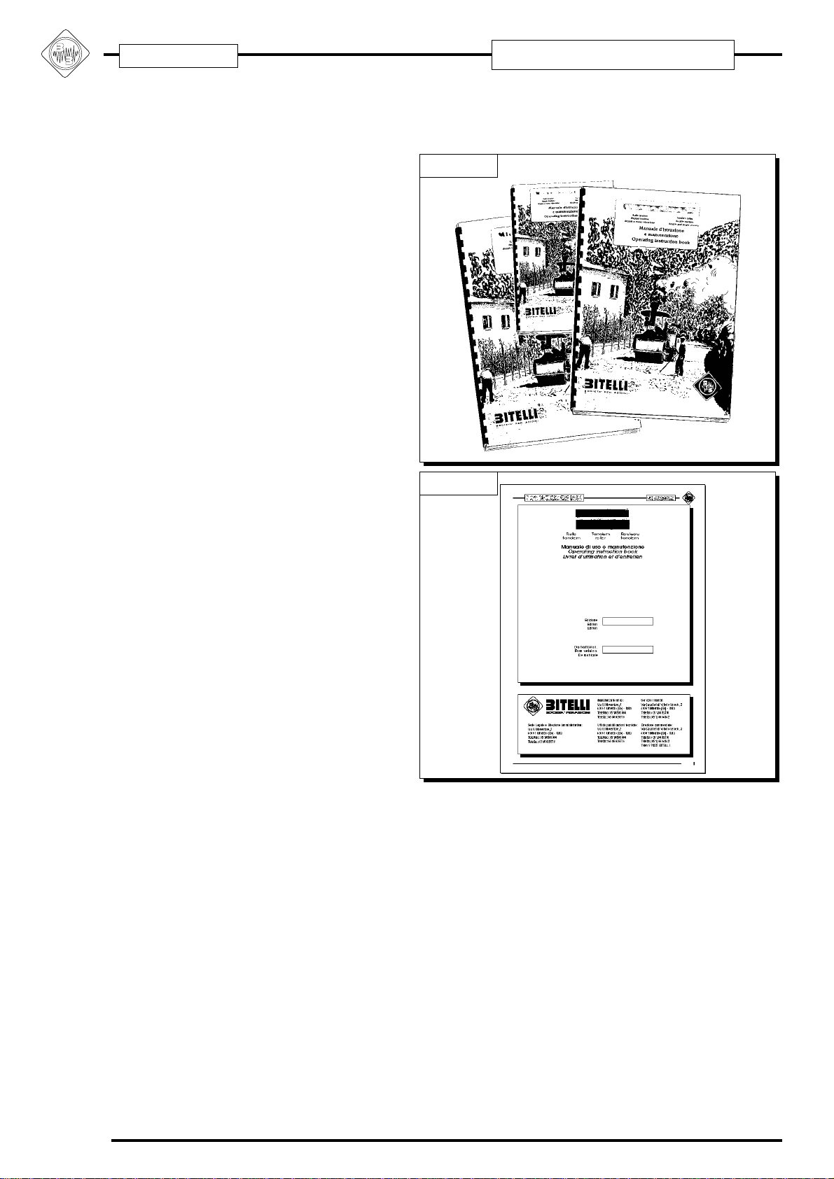
Questo Manuale è composto da 281 pagine.
This Book includes 281 pages.
Ce Livret comprend 281 pages.
JAN. 1995
Servizio Ricambi
Fax +39-051-6607114
Ufficio Pubblicazioni Tecniche
Fax +39-051-6607222
Sede Legale e Direzione Amministrativa
Via IV Novembre, 2
40061 MINERBIO (Bologna) - ITALIA
Tel. +39-051-6607111
Fax +39-051-6607458
www.bitelli.com
®
Direzione Commerciale
Fax +39-051-6607115
Assistenza Tecnica
Fax +39-051-6607113
Certificato Nr 50 100 1344
UNI EN ISO 9001:2000
Manuale di Uso e Manutenzione
Operating Instruction Book
Livret d'Utilisation et d'Entretien
Pulcino
DTV 310S
Pulcino
DTV 310S
Rullo
Tandem
Rouleau
Tandem
Roller
Tandem
Pulcino DTV 310S
II
DU-140049501A3
i- INTRO
Questomanualeédaconsiderarsiparteintegrantedella
fornitura della macchina, qualora risultasse rovinato o
illeggibile in qualsiasi parte occorre richiederne imme-
diatamente una copia.
Leggere attentamente le avvertenze riguardanti la sicu-
rezza d’uso, la manutenzione e le informazioni descritti-
ve.
La Bitelli S.p.A. declina ogni responsabilità per uso
impropriodellamacchina,perdannicausatiinseguitoad
operazioninoncontemplateinquestomanualeoirragio-
nevoli.
La macchina deve essere utilizzata solo per soddisfare
le esigenze per cui é stata espressamente concepita;
ogni altro uso é ritenuto pericoloso.
La Bitelli S.p.A. si ritiene responsabile della macchina
solonellasuaconfigurazioneoriginalestabilitainfasedi
progettazione.
Ogniinterventochemodifichilastrutturaeilciclodifunziona-
mentodellamacchinadeveessereautorizzatoespressamen-
tesolodall’ufficiotecnicodellalaBitelliS.p.A..
Utilizzare solo ed esclusivamente ricambi originali, la
Bitelli S.p.A. non si ritiene responsabile per i danni
causati in seguito all’utilizzo di ricambi non originali.
LaBitelliS.p.A.siriservaildirittodimodificareilprogetto
e di apportare migliorie senza comunicarlo ai clienti già
in possesso di modelli similari.
Tutti i diritti di riproduzione del presente manuale sono
riservati alla Bitelli S.p.A..
Il presente manuale non può essere ceduto in visione a
terzi senza autorizzazione scritta della Bitelli S.p.A.
SOCIETA' PER AZIONI
i
.1
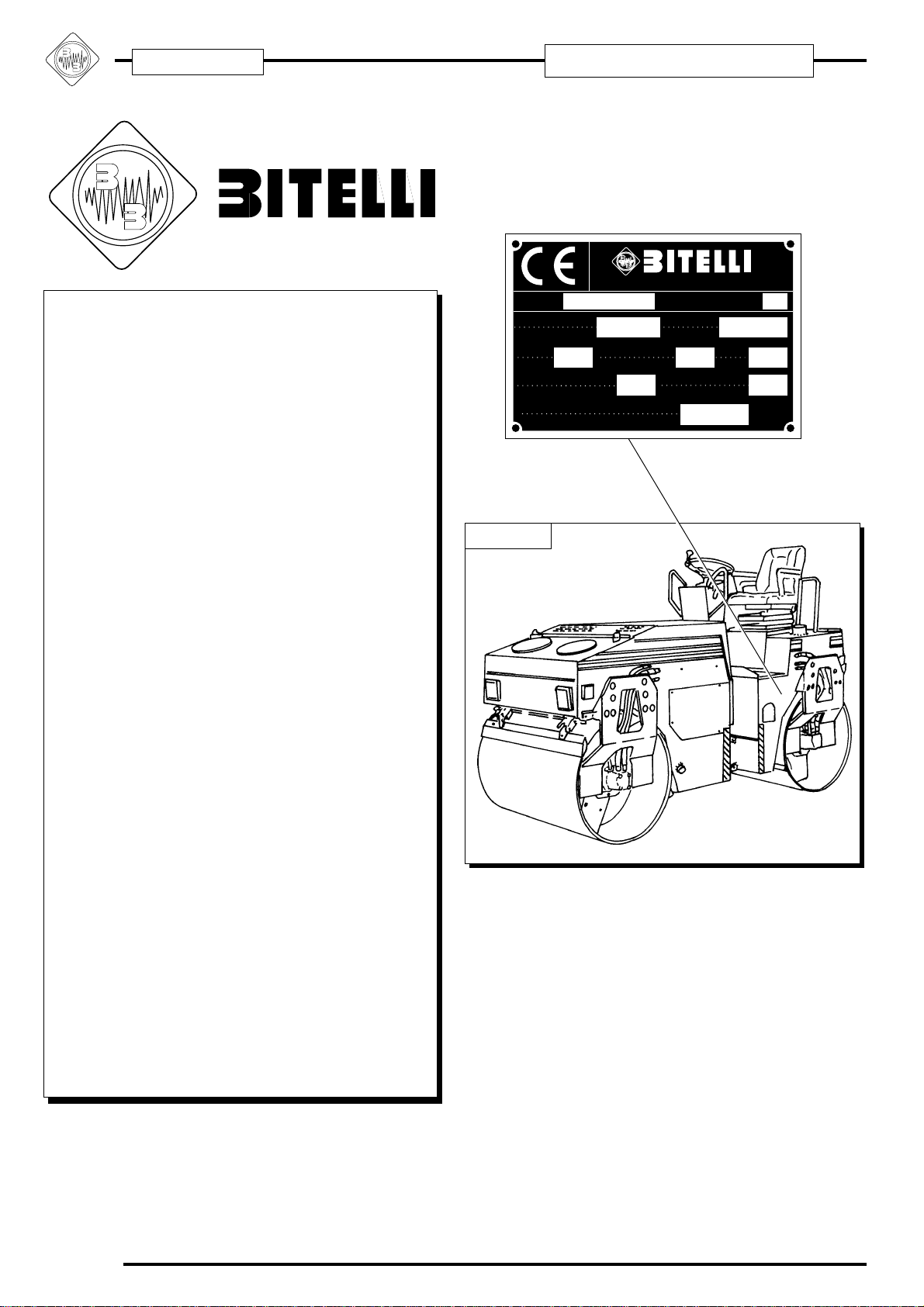
BB00014
Via IV Novembre, 2 - MINERBIO (BOLOGNA) ITALIA
MACCHINA MODELLO
MACHINE MODEL
N° MATRICOLA
SERIAL NUMBER
TIPO
TYPE
POTENZA
ENGINE POWER
giri/1'
rpm
MASSA COMPLESSIVA Kg
OVERALL MASS
SFORZO AMMISSIBILE AL GANCIO DI TRAINO N
MAX PULL ON THE TOWING HOOK
ANNO DI FABBRICAZIONE
PRODUCTION YEAR
COEFF. DI ASSORB. CORRETTO
DGM. OL
0
0
kW
BB00581
R.:48/97

III
Pulcino DTV 310S
i
- I
NTRO
i
- I
NTRO
DU-140049501A3
SOCIETA' PER AZIONI
SOCIETA' PER AZIONI
Thismanualshouldbeconsideredasanintegralpartof
your Bitelli machine like any other component. If it
becomes damaged or illegible you should request a
replacement immediately from the manufacturer.
Read the contents of this manual carefully.
Bitelli S.p.A. declines all responsibility for improper use
of the machine and for any damages caused by
operations not described in this manual or otherwise
considered as unreasonable use.
The machine must only be used for the purposes for
which it was designed; using the machine for any other
purpose can be dangerous.
Bitelli S.p.A. only accepts responsibility for machines
which conform to their original design.
Any modification to the structure or operating cycle of
the machine must be expressly authorised beforehand
by the Technical Office of Bitelli S.p.A.
OnlyuseoriginalBitellispareparts.BitelliS.p.A.declines
all responsibility for damage caused by use of non-
original spare parts.
Bitellioperatesapolicyofcontinuousimprovementand
reserves the right to make changes in machine design
without prior notice.
Bitelli S.p.A. guarantees the accuracy of the original
Italian language version of this manual but cannot fully
guaranteetheaccuracyofanytranslations.Intheevent
of discrepancies between a translated version and the
Italian, the Italian version only applies.
Ce manuel fait partie intégrante de la fourniture, et s’il
devait s’abîmer ou devenir illisible, demandez
immédiatement un autre exemplaire.
Veuillez lire attentivement les recommandations
concernant la sécurité d’emploi, l’entretien et les
informations relatives à la description.
Bitelli S.p.A. ne pourra en aucun cas être tenue
responsable d’une mauvaise utilisation de la machine
et des préjudices occasionnés par des opérations non
conformes aux instructions du manuel.
La machine ne doit être utilisée qu’aux fins pour
lesquelles elle a été expressément conçue, tout autre
emploi étant considéré comme dangereux.
LaresponsabilitédeBitelliS.p.A.neconcernequelamachine
telle qu’elle a été conçue dans sa configuration d’origine.
Toute intervention entraînant une modification de la
structure et du cycle de fonctionnement de la machine
ne peut être effectuée que si elle a été expressément
autorisée par le bureau technique de Bitelli S.p.A.
Utilisez uniquement des pièces détachées d’origine.
Bitelli S.p.A. ne saurait en aucun cas être tenue
responsabledesdommagesrésultantdel’utilisationde
pièces détachées non certifiées d’origine.
BitelliS.p.A.seréserveledroitdemodifierleprojetetd’apporter
des améliorations en vue sans devoir le communiquer aux
clients possédant des modèles similaires.
Touslesdroitsdereproductionduprésentmanuelsont
réservés à Bitelli S.p.A.
Le présent manuel ne pourra en aucun cas être cédé à
destierssans l’autorisation préalable et écrite de Bitelli
S.p.A.
R.:48/97

Pulcino DTV 310S
IV
DU-140049501A3
i- INTRO
Sommario
i.1 Avvertenze importantI............................................XII
i.2 Struttura del manuale.......................................... XVI
i.3 Descrizione icone.............................................. XVIII
i.4 Qualifica degli operatori addetti alla macchina... XXII
i.5 Utilizzo della simbologia ad icone .....................XXVI
Cap. 1 Generalità............................ 1.1
1.1 Identificazione del rullo tandem .......................... 1.2
1.2 Conformità alle norme CEE ................................ 1.4
1.3 Servizio di assistenza ......................................... 1.6
1.3.1 Parti di ricambio ..................................................... 1.6
1.4 Garanzia, controlli prima della consegna
e installazione ......................................................... 1.10
1.5 Antinfortunistica generale.................................. 1.12
1.5.1 Norme generali..................................................... 1.12
1.5.2 Personale autorizzato .......................................... 1.14
1.5.3 Modifiche o variazioni strutturali alla macchina .... 1.14
1.5.4 Targhette di sicurezza o decalcomanie ................ 1.14
1.5.5 Istruzioni dell’operatore ........................................ 1.16
1.5.6 Abbigliamento protettivo ....................................... 1.16
1.5.7 Trasporto persone ................................................ 1.18
1.5.8 Sollevamento ....................................................... 1.18
1.5.9 “ROPS” Telaio di sicurezza .................................. 1.22
1.5.10 Avviamento macchina ........................................ 1.24
1.5.10.1 Operazioni di preavviamento ...................... 1.24
1.5.10.2 Avviamento ................................................. 1.26
1.5.11 Durante il funzionamento.................................... 1.30
1.5.12 Guida sui pendii e sui terreni accidentati. .......... 1.32
1.5.12.1 Limiti di ribaltamento della macchina.......... 1.32
1.5.12.2 Limite massimo di lavoro ............................ 1.32
1.5.13 Spegnimento e rimessaggio............................... 1.32
1.5.14 Rifornimenti ........................................................ 1.34
1.5.15 Fluidi................................................................... 1.34
1.5.16 Circuito idraulico................................................. 1.34
1.5.17 Manutenzione della macchina............................ 1.36
1.5.18 Riassunto delle norme per la sicurezza tecnica . 1.42
1.5.18.1 Motore......................................................... 1.42
1.5.18.2 Manutenzione del motore ........................... 1.42
1.5.18.3 Impianto elettrico ........................................ 1.42
1.5.18.4 Sedili - comandi .......................................... 1.44
1.5.18.5 Impianto idraulico........................................ 1.44
1.5.18.6 Freni............................................................ 1.44
1.5.19 Chiusura cofano motore ..................................... 1.46
1.6 Posizione delle decalcomanie........................... 1.48
1.7 ROPS Telaio di sicurezza “fisso”....................... 1.58
1.7.1 Identificazione del telaio di sicurezza (ROPS) ..... 1.58
1.7.2 Caratteristiche particolari ..................................... 1.58
1.7.3 Modalità di installazione ....................................... 1.60
1.7.4 Utilizzo della macchina con il telaio di sicurezza
(ROPS).......................................................................... 1.60
1.7.5 Manutenzione relativa al telaio di sicurezza (ROPS) .. 1.60
1.7.6 Smontaggio del telaio di sicurezza (ROPS) ......... 1.62
1.8 ROPS Telaio di sicurezza “pieghevole”............. 1.64
1.8.1 Identificazione del telaio di sicurezza (ROPS) ..... 1.64
1.8.2 Caratteristiche particolari ..................................... 1.64
1.8.3 Modalità di installazione ....................................... 1.66

V
Pulcino DTV 310S
i
- I
NTRO
i
- I
NTRO
DU-140049501A3
Contents
i.1 Safety information ................................................XIII
i.2 About this manual............................................... XVII
i.3 Description of symbols used in this manual ........ XIX
i.4 Operator and maintenance technician qualifications .XXIII
i.5 Symbols and legends used in this manual.......XXVII
Unit 1 General information ............ 1.1
1.1 Roller identification..............................................1.3
1.2 Conformity to EC standards................................ 1.5
1.3 After-sales service............................................... 1.7
1.3.1 Spare parts............................................................. 1.7
1.4 Guarantee, pre-delivery checks
and installation ........................................................ 1.11
1.5 Safety precautions ............................................ 1.13
1.5.1 General safety precautions .................................. 1.13
1.5.2 Personnel authorised to use the machine ............ 1.15
1.5.3 Structural modifications to the machines ............. 1.15
1.5.4 Safety labels and decals ...................................... 1.15
1.5.5 Safety instructions for the machine operator........ 1.17
1.5.6 Protective garments ............................................. 1.17
1.5.7 Passengers .......................................................... 1.19
1.5.8 Hoisting ................................................................ 1.19
1.5.9 ROPS Rollover protection structures ................... 1.23
1.5.10 Starting ............................................................... 1.25
1.5.10.1 Safety checks before starting the machine. 1.25
1.5.10.2 Safety precautions when starting................ 1.27
1.5.11 Safety precautions during operation................... 1.31
1.5.12 Driving on slopes and uneven terrain................. 1.33
1.5.12.1 Machine tipping limits: ................................ 1.33
1.5.12.2 Maximum working limit ............................... 1.33
1.5.13 Switching off and garaging the machine ............ 1.33
1.5.14 Safe use of fuels ................................................ 1.35
1.5.15 Fluids.................................................................. 1.35
1.5.16 Hydraulic circuit .................................................. 1.35
1.5.17 Safety precautions during maintenance ............. 1.37
1.5.18 Summary of safety precautions.......................... 1.43
1.5.18.1 Engine......................................................... 1.43
1.5.18.2 Engine maintenance ................................... 1.43
1.5.18.3 Electrical equipment ................................... 1.43
1.5.18.4 Driver’s seat and controls .......................... 1.45
1.5.18.5 Hydraulic system ........................................ 1.45
1.5.18.6 Brakes......................................................... 1.45
1.5.19 Engine cover lock ............................................... 1.47
1.6 Position of decalson the machine ..................... 1.49
1.7 Fixed Roll Over Protection frame (ROPS) ........ 1.59
1.7.1 Identifying the Roll Over Protection frame (ROPS)1.59
1.7.2 Special features ................................................... 1.59
1.7.3 Fitting the ROPS frame ........................................ 1.61
1.7.4 Using the ROPS safety frame .............................. 1.61
1.7.5 Maintenance of the ROPS frame ......................... 1.61
1.7.6 Dismantling the ROPS frame ............................... 1.63
1.8 Folding Roll Over Protection frame (ROPS) ..... 1.65
1.8.1 Identifying the Roll Over Protection frame (ROPS)1.65
1.8.2 Special features ................................................... 1.65
1.8.3 Fitting the ROPS frame ........................................ 1.67
Sommaire
i.1 Recommandations importantes ...........................XIII
i.2 Structure du manuel........................................... XVII
i.3 Description des icônes ........................................ XIX
i.4 Qualification des opérateurs ............................. XXIII
i.5 Utilisation de symboles à icônes ......................XXVII
Chap. 1 Généralités........................ 1.1
1.1 Identification du rouleau tandem......................... 1.3
1.2 Conformité aux normes CEE .............................. 1.5
1.3 Service après-vente ............................................1.7
1.3.1 Pièces détachées................................................... 1.7
1.4 Garantie, contrôles à effectuer avant la livraison et
l’installation ........................................................ 1.11
1.5 Règles de sécurité générales ........................... 1.13
1.5.1 Règles générales ................................................. 1.13
1.5.2 Personnel autorisé ............................................... 1.15
1.5.3 Modifications ou variations de la structure de la
machine .................................................................... 1.15
1.5.4 Plaquettes de sécurité ou autocollants ................ 1.15
1.5.5 Consignes pour l’opérateur .................................. 1.17
1.5.6 Vêtements de protection ...................................... 1.17
1.5.7 Transport de passagers........................................ 1.19
1.5.8 Levage ................................................................. 1.19
1.5.9 Châssis de sécurité "ROPS" ................................ 1.23
1.5.10 Démarrage de la machine.................................. 1.25
1.5.10.1 Opérations de pré-démarrage .................... 1.25
1.5.10.2 Mise en route .............................................. 1.27
1.5.11 Pendant la marche ............................................. 1.31
1.5.12 Conduite dans les descentes et sur les terrains
accidentés................................................................. 1.33
1.5.12.1 Limites du débattement de la machine: ...... 1.33
1.5.12.2 Limite maximale de travail .......................... 1.33
1.5.13 Pour arrêter et garer la machine ........................ 1.33
1.5.14 Pleins ................................................................. 1.35
1.5.15 Fluides............................................................... 1.35
1.5.16 Circuit hydraulique ............................................. 1.35
1.5.17 Entretien de la machine ..................................... 1.37
1.5.18 Récapitulatif des règles de sécurité ethnique .... 1.43
1.5.18.1 Moteur......................................................... 1.43
1.5.18.2 Entretien du moteur ................................... 1.43
1.5.18.3 Circuit électrique ......................................... 1.43
1.5.18.4 Sièges - Commandes ................................. 1.45
1.5.18.5 Circuit hydraulique ...................................... 1.45
1.5.18.6 Freins.......................................................... 1.45
1.5.19 Fermeture du capot moteur................................ 1.47
1.6 Emplacement des autocollants .........................1.49
1.7 ROPS Châssis de sécurité “fixe” ...................... 1.59
1.7.1 Identification du châssis de sécurité (ROPS) ....... 1.59
1.7.2 Caractéristiques particulières ............................... 1.59
1.7.3 Installation ............................................................ 1.61
1.7.4 Utilisation de la machine avec le châssis de sécurité
(ROPS) ..................................................................... 1.61
1.7.5 Entretien du châssis de sécurité (ROPS)............. 1.61
1.7.6 Dépose du châssis de sécurité (ROPS)............... 1.63
1.8 ROPS Châssis de sécurité “pliant” ................... 1.65
1.8.1 Identification du châssis de sécurité (ROPS) ....... 1.65
1.8.2 Caractéristiques particulières ............................... 1.65
1.8.3 Installation ............................................................ 1.67

Pulcino DTV 310S
VI
DU-140049501A3
i- INTRO
1.8.4 Utilizzo della macchina con il telaio di sicurezza (ROPS)1.66
1.8.5 Manutenzione relativa al telaio di sicurezza (ROPS) ....1.66
1.8.6 Smontaggio del telaio di sicurezza (ROPS) ......... 1.68
Cap. 2 Informazioni preliminari..... 2.1
2.1 Descrizione generale .......................................... 2.2
2.1.1 Specifiche particolari .............................................. 2.4
2.1.2 Posizionamento organi principali ........................... 2.4
2.2 Caratteristiche strutturali ..................................... 2.6
2.2.1 Telaio ...................................................................... 2.6
2.2.2 Motore .................................................................... 2.6
2.2.3 Insonorizzazione .................................................... 2.6
2.2.4 Vibrazioni................................................................ 2.6
2.2.5 Sterzo ..................................................................... 2.6
2.2.6 Traslazione ............................................................. 2.8
2.2.7 Apparato vibrante ................................................... 2.8
2.2.8 Impianto idraulico ................................................... 2.8
2.2.9 Dispositivi di frenatura ............................................ 2.8
2.2.10 Impianto di irrorazione........................................ 2.10
2.2.11 Posto di guida..................................................... 2.10
2.2.12 Sistema presenza operatore .............................. 2.10
2.2.13 Impianto elettrico ................................................ 2.10
2.2.14 Strumenti quadro comandi ................................. 2.12
2.2.15 Fusibili ................................................................ 2.12
2.2.16 Applicazioni ausiliarie ......................................... 2.12
2.3 Dati tecnici ........................................................ 2.14
2.3.1 Caratteristiche generali ........................................ 2.14
2.3.2 Dimensioni ........................................................... 2.16
2.3.3 Traslazione ........................................................... 2.16
2.3.4 Vibrazione ............................................................ 2.16
2.3.5 Rifornimenti .......................................................... 2.16
2.3.6 Impianto elettrico (fino alla matricola
140.95.0125) ................................................................. 2.18
2.3.6.1 Colore dei cavi come appaiono sul disegno . 2.18
2.3.6.2 Legenda componenti impianto elettrico
(valido fino alla matricola 140.95.0125) .................... 2.20
2.3.6.3 Fusibili nella scatola colonna volante ........... 2.22
2.3.6.3/A Fusibile generale protezione impianto....... 2.22
2.3.6.4 Schema elettrico (fino alla matricola
140.95.0125)............................................................. 2.24
2.3.7 Impianto elettrico (dalla matricola 140.95.0126) ......2.26
2.3.7.1 Colore dei cavi come appaiono sul disegno . 2.26
2.3.7.2 Componenti (dalla matricola 140.95.0126)... 2.28
2.3.7.3 Fusibili nella scatola colonna verticale.......... 2.32
2.3.7.4 Fusibile generale protezione impianto .......... 2.32
2.3.7.5 Schema elettrico(dalla matricola
140.95.0126)............................................................. 2.34
2.3.8 Schemi idraulici .................................................... 2.36
2.3.8.1 Schema idraulico traslazione e freno
(valido fino alla matricola 140.95.0125) .................... 2.36
2.3.8.2 Schema idraulico traslazione e freno
(valido dalla matricola 140.95.0126)......................... 2.38
2.3.8.3 Schema idraulico vibrazione e sterzo ........... 2.40
Cap. 3 Sollevamento e trasporto .. 3.1
3.1 Antinfortunistiche sul sollevamento..................... 3.2
3.2 Sollevamento ...................................................... 3.6
3.2.1 Bloccaggio dello sterzo .......................................... 3.6
3.2.2 Sollevamento ......................................................... 3.6
3.3 Trasporto............................................................. 3.8
3.4 Traino macchina................................................ 3.10
3.5 Rimessaggio ..................................................... 3.12

VII
Pulcino DTV 310S
i
- I
NTRO
i
- I
NTRO
DU-140049501A3
1.8.4 Using the ROPS safety frame .............................. 1.67
1.8.5 Maintenance of the ROPS frame ......................... 1.67
1.8.6 Dismantling the ROPS frame ............................... 1.69
Unit 2 Descriptions ........................ 2.1
2.1 General description............................................. 2.3
2.1.1 Main features ......................................................... 2.5
2.1.2 Position of main mechanical and hydraulic units ... 2.5
2.2 Structural features............................................... 2.7
2.2.1 Frame ..................................................................... 2.7
2.2.2 Engine .................................................................... 2.7
2.2.3 Noise level.............................................................. 2.7
2.2.4 Vibration ................................................................. 2.7
2.2.5 Steering .................................................................. 2.7
2.2.6 Transmission .......................................................... 2.9
2.2.7 Vibrator equipment ................................................ 2.9
2.2.8 Hydraulic equipment .............................................. 2.9
2.2.9 Braking system....................................................... 2.9
2.2.10 Water sprinkling equipment................................ 2.11
2.2.11 Driving position ................................................... 2.11
2.2.12 Operator presence system ................................. 2.11
2.2.13 Electrical equipment ........................................... 2.11
2.2.14 Dashboard controls ............................................ 2.13
2.2.15 Fuses ................................................................. 2.13
2.2.16 Additional equipment.......................................... 2.13
2.3 Specifications .................................................... 2.15
2.3.1 Main Specifications .............................................. 2.15
2.3.2 Dimensions .......................................................... 2.17
2.3.3 Drive and transmission......................................... 2.17
2.3.4 Vibration ............................................................... 2.17
2.3.5 Tank capacities..................................................... 2.17
2.3.6 Electrical equipment
(up to serial number 140.95.0125) ................................ 2.19
2.3.6.1 Cable colour codes ....................................... 2.19
2.3.6.2 Legend of electrical components
(up to serial number 140.95.0125)............................ 2.21
2.3.6.3 Fuses in fuse box on steering column .......... 2.23
2.3.6.3/AAmp main fuse........................................... 2.23
2.3.6.4 Electrical circuit diagram (up to serial number
140.95.0125)............................................................. 2.25
2.3.7 Electrical equipment (from to serial number
140.95.0126 onwards) .................................................. 2.27
2.3.7.1 Cable colour codes ....................................... 2.27
2.3.7.2 Components (from serial number 140.95.0126) ...2.29
2.3.7.3 Fuses in the vertical column box .................. 2.33
2.3.7.4 Main fuse ...................................................... 2.33
2.3.7.5 Electrical circuit diagram (from serial number
140.95.0126)...................................................... 2.35
2.3.8 Hydraulic circuit diagrams .................................... 2.37
2.3.8.1 Hydraulic circuit diagram: transmission and brake
systems (up to serial number 140.95.0125)....... 2.37
2.3.8.2 Hydraulic diagram for vibrator and steering (from
serial n. 140.95.0126 onwards).......................... 2.39
2.3.8.3Hydraulic circuitdiagram:vibratorandsteering systems .. 2.41
Unit 3 Hoisting and transport........ 3.1
3.1 Safety precautions during hoisting...................... 3.3
3.2 Hoisting the machine .......................................... 3.7
3.2.1 Clamping the central steering joint ......................... 3.7
3.2.2 Hoisting .................................................................. 3.7
3.3 Transport ............................................................. 3.9
3.4 Towing the machine .......................................... 3.11
3.5 Storage ............................................................. 3.13
1.8.4 Utilisation machine avec châssis de sécurité (ROPS) ..1.67
1.8.5 Entretien du châssis de sécurité (ROPS)............. 1.67
1.8.6 Dépose du châssis de sécurité (ROPS)............... 1.69
Chap. 2 Avant-propos .................... 2.1
2.1 Renseignements préliminaires............................ 2.3
2.1.1 Caractéristiques spéciales ..................................... 2.5
2.1.2 Emplacement des organes principaux ................... 2.5
2.2 Caractéristiques structurelles.............................. 2.7
2.2.1 Châssis .................................................................. 2.7
2.2.2 Moteur .................................................................... 2.7
2.2.3 Insonorisation ......................................................... 2.7
2.2.4 Vibrations ............................................................... 2.7
2.2.5 Direction ................................................................. 2.7
2.2.6 Transmission .......................................................... 2.9
2.2.7 Appareil vibrant ...................................................... 2.9
2.2.8 Circuit hydraulique ................................................. 2.9
2.2.9 Dispositif de freinage.............................................. 2.9
2.2.10 Circuit d’arrosage ............................................... 2.11
2.2.11 Poste de conduite............................................... 2.11
2.2.12 Système de contrôle de la présence de l’opérateur ... 2.11
2.2.13 Circuit électrique ................................................ 2.11
2.2.14 Appareils du tableau de bord ............................. 2.13
2.2.15 Fusibles .............................................................. 2.13
2.2.16 Applications auxiliaires ....................................... 2.13
2.3 Données techniques ......................................... 2.15
2.3.1 Caractéristiques générales .................................. 2.15
2.3.2 Dimensions .......................................................... 2.17
2.3.3 Translation............................................................ 2.17
2.3.4 Vibration ............................................................... 2.17
2.3.5 Pleins ................................................................... 2.17
2.3.6 Circuit électrique (valable jusqu'au n. de série
140.95.0125)............................................................. 2.19
2.3.6.1 Couleur des câbles indiqués sur le schéma . 2.19
2.3.6.2 Légende composants équipement électrique
(valable jusqu’au numéro de série 140.95.0125)...... 2.21
2.3.6.3 F Fusibles dans la boîte colonne volant ....... 2.23
2.3.6.3/A Fusible général de protection du circuit..... 2.23
2.3.6.4 Schéma électrique (jusqu'au numero de serie
140.95.0125)............................................................. 2.25
2.3.7 Circuit électrique (a partir du numéro di série
140.95.0126) ................................................................. 2.27
2.3.7.1 Couleur des câbles indiqués sur le schéma . 2.27
2.3.7.2 Eléments constitutif (a partir du numéro
de série 140.95.0126)............................................... 2.29
2.3.7.3 Fusibles dans la boîte sur la colonne de direction.2.33
2.3.7.4 Fusible général de protection du circuit ........ 2.33
2.3.7.5 Schéma électrique (a partir du numéro di série
140.95.0126)...................................................... 2.35
2.3.8 Schémas hydrauliques ......................................... 2.37
2.3.8.1 Schéma hydraulique translation et frein (valable
jusqu’au numéro de série 140.95.0125) ............ 2.37
2.3.8.2 Schéma hydraulique de translation et de frein
(valable à partir du n
°
de série 140.95.0126)..... 2.39
2.3.8.3 Schéma hydraulique vibration et direction.... 2.41
Chap. 3 Levage et transport.......... 3.1
3.1 Règles de sécurité sur le levage......................... 3.3
3.2 Levage ................................................................ 3.7
3.2.1 Blocage de la direction ........................................... 3.7
3.2.2 Levage ................................................................... 3.7
3.3 Transport ............................................................. 3.9
3.4 Remorquage de la machine.............................. 3.11
3.5 Remisage .......................................................... 3.13

Pulcino DTV 310S
VIII
DU-140049501A3
i- INTRO
Cap. 4 Avviamento macchina........ 4.1
4.1 Antinfortunistica relativa all’avviamento .............. 4.2
4.2 Sistemi di sicurezza adottati ............................... 4.8
4.2.1 Sistema autofrenante ............................................. 4.8
4.2.2 Ribaltamento .......................................................... 4.8
4.2.3 Decalcomanie ........................................................ 4.8
4.2.4 Sistema presenza operatore .................................. 4.8
4.3 Comandi e strumenti di controllo ..................... 4.10
4.3.1 Descrizione comandi e strumenti ......................... 4.12
4.3.1.1 Leva comando acceleratore ......................... 4.12
4.3.1.2 Contaore ....................................................... 4.12
4.3.1.3 Chiave di contatto, accensione e arresto motore ..4.14
4.3.1.4 Spia alternatore ............................................ 4.16
4.3.1.5 Spia pressione olio motore ........................... 4.16
4.3.1.6 Spia alta temperatura motore ....................... 4.16
4.3.1.7 Leva di comando traslazione AVANTI-INDIETRO4.18
4.3.1.8 Volante di guida ............................................ 4.20
4.3.1.9 Comando freno d’emergenza/parcheggio .... 4.22
4.3.1.10 Spia freno inserito....................................... 4.24
4.3.1.11 Commutatore luci/comando avvisatore acustico ..4.26
4.3.1.12 Spia luci di posizione/anabbaglianti/
di lavoro .................................................................... 4.26
4.3.1.13 Comando indicatori di direzione ................. 4.26
4.3.1.14 Spia indicatori di direzione.......................... 4.26
4.3.1.15 Scatola porta fusibili.................................... 4.28
4.3.1.16 Fusibile generale protezione impianto "40A".. 4.28
4.3.1.17 Comando vibrante ...................................... 4.30
4.3.1.18 Rubinetto impianto acqua ........................... 4.30
4.3.1.19 Interruttore comando pompa elettrica......... 4.32
4.3.1.20 Spia pompa elettrica ................................... 4.32
4.4 Dispositivi di illuminazione e segnalazione ....... 4.34
4.5 Apparati di segnalazione................................... 4.36
4.5/A Isolamento dalle fonti di energia .................4.36/A
4.5/A.1 Isolamento batteria ........................................4.36/A
4.6 Protezioni antivandalismi .................................. 4.38
4.7 Rifornimenti, livelli e scarichi............................. 4.40
4.7.1 Serbatoio gasolio ................................................. 4.40
4.7.2 Serbatoio olio idraulico ......................................... 4.40
4.7.3 Serbatoio acqua ................................................... 4.42
4.8 Preavviamento .................................................. 4.44
4.8.1 Controlli sulla macchina ....................................... 4.44
4.9 Regolazione sedile............................................4.48
4.10 Avviamento del motore.................................... 4.50
4.11 Arresto motore................................................. 4.50
Cap. 5 Manutenzione ..................... 5.1
5.1 Descrizione generale .......................................... 5.2
5.2 Periodo di rodaggio............................................. 5.4
5.3 Antinfortunistica sulla manutenzione................... 5.6
5.4 Tabella riassuntiva di manutenzione ................. 5.14
5.5 Tabelle per i rifornimenti.................................... 5.20
5.5.1 Tipi di rifornimenti ................................................. 5.20
5.5.2 Caratteristiche dei lubrificanti ............................... 5.20
5.5.3 Tipi di olio in relazione alla temperatura ............... 5.22
5.5.3.1 Olio per motore diesel................................... 5.22
5.5.4 Tabella comparativa degli oli ................................ 5.22
5.5.5 Olio Agip per impianto idraulico............................ 5.22

IX
Pulcino DTV 310S
i
- I
NTRO
i
- I
NTRO
DU-140049501A3
Unit 4 Starting the machine........... 4.1
4.1 Safety precautions during starting ...................... 4.3
4.2 Safety systems fitted to the machine .................. 4.9
4.2.1 Fail safe braking system ........................................ 4.9
4.2.2 Roll Over Protection System (ROPS) .................... 4.9
4.2.3 Decals .................................................................... 4.9
4.2.4 Operator presence system ..................................... 4.9
4.3 Controls and instruments .................................. 4.11
4.3.1 Description of controls and instruments ............... 4.13
4.3.1.1 Accelerator lever ........................................... 4.13
4.3.1.2 Hour counter ................................................. 4.13
4.3.1.3 Ignition key, starter and engine cut-out ......... 4.15
4.3.1.4 Alternator warning light ................................. 4.17
4.3.1.5 Engine oil pressure warning light.................. 4.17
4.3.1.6 Engine high temperature warning light ......... 4.17
4.3.1.7 FORWARD-REVERSE lever ........................ 4.19
4.3.1.8 Steering wheel .............................................. 4.21
4.3.1.9 Parking and emergency brake lever ............. 4.23
4.3.1.10 Brake on warning light ................................ 4.25
4.3.1.11 Light switch/horn ......................................... 4.27
4.3.1.12 Warning light, sidelights/dipped
beam/work light......................................................... 4.27
4.3.1.13 Direction indicators, switch ......................... 4.27
4.3.1.14 Direction indicators, warning light ............... 4.27
4.3.1.15 Fuse box ..................................................... 4.29
4.3.1.16 40 Amp main fuse ....................................... 4.29
4.3.1.17 Vibrator switch ............................................ 4.31
4.3.1.18 Sprinkler system tap ................................... 4.31
4.3.1.19 Electric pump, switch .................................. 4.33
4.3.1.20 Electric pump, warning light........................ 4.33
4.4 Lighting equipment............................................4.35
4.5 Rotary beacon...................................................4.37
4.5/A Battery isolator switch.................................... 4.55
4.5/A.1 Isolating the battery .......................................... 4.55
4.6 Anti-theft protection ........................................... 4.39
4.7 Tanks: filling, levels and draining ...................... 4.41
4.7.1 Fuel tank .............................................................. 4.41
4.7.2 Hydraulic oil tank .................................................. 4.41
4.7.3 Water tank ............................................................ 4.43
4.8 Before you start the machine ............................ 4.45
4.8.1 Preliminary checks ............................................... 4.45
4.9 Seat adjustment ................................................ 4.49
4.10 Starting the engine.......................................... 4.51
4.11 Stopping the engine ........................................ 4.51
Unit 5 Maintenance ........................ 5.1
5.1 General maintenance instructions ...................... 5.3
5.2 Running-in period................................................5.5
5.3 Safety precautions during maintenance..............5.7
5.4 Maintenance table............................................. 5.15
5.5 Fuel and lubricant tables................................... 5.21
5.5.1 Recommended products and amounts ................ 5.21
5.5.2 Lubricant specifications ........................................ 5.21
5.5.3 Oil/temperature table............................................ 5.23
5.5.3.1 Diesel engine oil ........................................... 5.23
5.5.4 Comparative table of oils...................................... 5.23
5.5.5 AGIP Hydraulic oil ................................................ 5.23
Chap. 4 Mise en route de la machine . 4.1
4.1 Règles de sécurité relatives à la mise en route .. 4.3
4.2 Dispositifs de sécurité adoptés ........................... 4.9
4.2.1 Dispositif autofreinant............................................. 4.9
4.2.2 Retournement ........................................................ 4.9
4.2.3 Autocollants ............................................................ 4.9
4.2.4 Système de présence opérateur ............................ 4.9
4 .3 Commandes et appareils de contrôle ............ 4.11
4.3.1 Description des commandes et des appareils ..... 4.13
4.3.1.1 Levier de commande de l’accélérateur......... 4.13
4.3.1.2 Compteur horaire.......................................... 4.13
4.3.1.3 Clé de contact, mise en route et arrêt du moteur ..4.15
4.3.1.4 Voyant de l’alternateur .................................. 4.17
4.3.1.5 Voyant de pression de l’huile moteur............ 4.17
4.3.1.6 Voyant de température élevée du moteur .... 4.17
4.3.1.7 Levier de commande de translation AVANT-
ARRIERE ........................................................... 4.19
4.3.1.8 Volant de conduite ........................................ 4.21
4.3.1.9 Commande frein de secours/stationnement . 4.23
4.3.1.10 Voyant du frein enclenche .......................... 4.25
4.3.1.11 Commutateur des feux/commande de
l’avertisseur sonore............................................ 4.27
4.3.1.12 Voyant des feux de position/de
croisement/de travail................................................. 4.27
4.3.1.13Commande des feux de direction ................ 4.27
4.3.1.14 Voyant des feux de direction ...................... 4.27
4.3.1.15 Boîte à fusibles ........................................... 4.29
4.3.1.16 Fusible général de protection du circuit “40A”.....4.29
4.3.1.17 Commande du vibreur ................................ 4.31
4.3.1.18 Robinet du circuit d’eau .............................. 4.31
4.3.1.19 Commande de la pompe électrique............ 4.33
4.3.1.20 Voyant de la pompe électrique ................... 4.33
4.4 Dispositifs d’éclairage ....................................... 4.35
4.5 Appareils de signalisation ................................. 4.37
4.5/A Dispositif de débranchement de la batterie 4.37/A
4.5/A.1 Isolement de la batterie .................................4.37/A
4.6 Protections antivandalisme ............................... 4.39
4.7 Pleins, niveaux et vidanges .............................. 4.41
4.7.1 Réservoir de gazole ............................................. 4.41
4.7.2 Réservoir de l’huile hydraulique ........................... 4.41
4.7.3 Réservoir d’eau .................................................... 4.43
4.8 Prédémarrage ................................................... 4.45
4.8.1 Contrôles à effectuer sur la machine ................... 4.45
4.9 Reglage du siège ..............................................4.49
4.10 Mise en route du moteur .................................4.51
4.11 Arrêt du moteur ............................................... 4.51
Chap. 5 Entretien............................ 5.1
5.1 Description générale ........................................... 5.3
5.2 Période de rodage .............................................. 5.5
5.3 Règles de sécurité relatives à l’entretien ............ 5.7
5.4 Tableau récapitulatif des opérations d’entretien 5.15
5.5 Tableaux des pleins .......................................... 5.21
5.5.1 Types de pleins .................................................... 5.21
5.5.2 Caractéristiques des lubrifiants ............................ 5.21
5.5.3 Types d’huile en fonction de la température......... 5.23
5.5.3.1 Huile pour moteur Diesel .............................. 5.23
5.5.4 Tableau comparatif des huiles.............................. 5.23
5.5.5 Huile Agip pour circuit hydraulique ....................... 5.23

Pulcino DTV 310S
X
DU-140049501A3
i- INTRO
5.6 Manutenzione ogni 10 ore di lavoro.................. 5.24
5.6.1 Controllo del livello olio motore ............................ 5.24
5.6.2 Controllo livello olio idraulico ................................ 5.24
5.6.3 Controllo livello carburante................................... 5.26
5.6.4 Controllo vacuometro filtro olio idraulico .............. 5.26
5.6.5 Controllo impianto lavaggio e barre raschiatamburi .....5.28
5.6.5.1 Controllare l’efficienza dell’impianto
acqua sui tamburi. .................................................... 5.28
5.6.5.2 Controllare lo stato di usura
delle barre raschiatrici tamburi.................................. 5.28
5.6.6 Controllo cartuccia filtro aria motore .................... 5.30
5.7 Manutenzione ogni 50 ore di lavoro.................. 5.32
5.7.1 Pulizia generale.................................................... 5.32
5.7.2 Ingrassaggio snodo articolazione centrale e martinetto .. 5.34
5.7.3 Pulizia radiatore olio idraulico .............................. 5.34
5.7.4 Controllo livello liquido batteria ............................ 5.36
5.7.4.1 Batterie senza manutenzione ....................... 5.36
5.7.4.2 Batteria con manutenzione ........................... 5.36
5.8 Manutenzione ogni 250 ore di lavoro................ 5.38
5.8.1 Sostituzione olio motore ....................................... 5.38
5.8.2 Sostituzione cartuccia filtro olio motore................ 5.40
5.8.3 Manutenzione filtro dell'aria.................................. 5.42
5.8.3.1 Pulizia da intasamento a secco .................... 5.42
5.8.3.2 Pulizia da intasamento umido o oleoso ........ 5.44
5.8.3.3 Controllo dell'elemento filtrante .................... 5.44
5.8.4 Controllo silentblock motore ................................. 5.46
5.8.5 Controllo tappi antivibranti del tamburo posteriore5.46
5.8.6 Pulizia sistema di raffreddamento del motore ...... 5.48
5.8.7 Controllo filtro carburante ..................................... 5.50
5.8.8 Controllo livello olio cassa vibrante tamburo posteriore .. 5.50
5.9 Manutenzione ogni 500 ore di lavoro................ 5.52
5.9.1 Sostituzione cartuccia filtro olio idraulico ............. 5.52
5.9.2 Sostituzione olio cassa vibrante ........................... 5.54
5.9.3 Controllo apparato gas di scarico e
aspirazione aria motore................................................. 5.54
5.9.4 Sostituzione filtro carburante................................ 5.56
5.10 Manutenzione ogni 1200 ore di lavoro............ 5.58
5.10.1 Pulizia serbatoio gasolio .................................... 5.58
5.10.2 Pulizia serbatoio acqua ...................................... 5.60
5.10.3 Pulizia serbatoio olio idraulico/sostituzione
cartuccia/sostituzione olio ............................................. 5.62
5.10.4 Controllo serraggio snodo
articolazione centrale .................................................... 5.64
5.11 Lunga inattività della macchina .......................5.66
5.12 Manutenzione impianto elettrico ..................... 5.68
5.12.1 Fari ..................................................................... 5.68
5.13 Tabella delle coppie di serraggio..................... 5.70
5.13.1 Raccordi dei tubi idraulici flessibili...................... 5.70
5.13.2 Viti e bulloni per collegamenti filettati ................. 5.70

XI
Pulcino DTV 310S
i
- I
NTRO
i
- I
NTRO
DU-140049501A3
5.6 Maintenance every 10 hours.............................5.25
5.6.1 Engine oil level ..................................................... 5.25
5.6.2 Hydraulic oil level ................................................. 5.25
5.6.3 Fuel level .............................................................. 5.27
5.6.4 Hydraulic oil filter vacuum meter .......................... 5.27
5.6.5 Roller sprinkler and roller scraper bars ................ 5.29
5.6.5.1 Roller sprinkler efficiency.............................. 5.29
5.6.5.2 Check the wear of the roller scraper bars..... 5.29
5.6.6 Check engine air filter cartridge ........................... 5.31
5.7 Maintenance every 50 hours.............................5.33
5.7.1 Cleaning ............................................................... 5.33
5.7.2 Central steering joint and cylinder ........................ 5.35
5.7.3 Cleaning the hydraulic oil cooler .......................... 5.35
5.7.4 Battery fluid level .................................................. 5.37
5.7.4.1 Maintenance-free batteries ........................... 5.37
5.7.4.2 Batteries requiring maintenance ................... 5.37
5.8 Maintenance every 250 hours........................... 5.39
5.8.1 Engine oil change................................................. 5.39
5.8.2 Engine oil filter cartridge change .......................... 5.41
5.8.3 Engine air filter ..................................................... 5.43
5.8.3.1 Cleaning dry dirt from the filter...................... 5.43
5.8.3.2 Cleaning wet or oil dirt from the filter ............ 5.45
5.8.3.3 Checking the filter element ........................... 5.45
5.8.4 Engine silentblocks .............................................. 5.47
5.8.5 Checking the silent-blocks on the rear drum ........ 5.47
5.8.6 Engine cooling system ......................................... 5.49
5.8.7 Diesel fuel filter cartridge condition ...................... 5.51
5.8.8 Vibrator box oil check rear drum .......................... 5.51
5.9 Maintenance every 500 hours........................... 5.53
5.9.1 Hydraulic oil filter cartridge change ...................... 5.53
5.9.2 Vibrator rear box oil change ................................. 5.55
5.9.3 Exhaust system and engine air intake system ..... 5.55
5.9.4 Main fuel filter cartridge change ........................... 5.57
5.10 Maintenance every 1200 hours.......................5.59
5.10.1 Cleaning the fuel tank ........................................ 5.59
5.10.2 Cleaning the water tank ..................................... 5.61
5.10.3 Cleaning the hydraulic oil tank ........................... 5.63
5.10.4 Checking the tightness of the central
steering joint .................................................................. 5.65
5.11 Prolonged period of idleness........................... 5.67
5.12 Maintenance of electrical equipment .............. 5.69
5.12.1 Headlights .......................................................... 5.69
5.13 Table of torque wrench settings ...................... 5.71
5.13.1 Hydraulic hose connectors ................................. 5.71
5.13.2 table of torque wrench settings for screws ......... 5.71
5.6 Entretien toutes les 10 heures de travail........... 5.25
5.6.1 Contrôle du niveau d’huile moteur ....................... 5.25
5.6.2 Contrôle du niveau d’huile hydraulique ................ 5.25
5.6.3 Contrôle du niveau de carburant .......................... 5.27
5.6.4 Contrôle du vacuomètre de filtre à huile hydraulique....5.27
5.6.5 Contrôle du circuit de lavage et des raclettes des
tambours................................................................... 5.29
5.6.5.1 Contrôler l’efficacité du circuit d’eau sur les
tambours. ........................................................... 5.29
5.6.5.2 Contrôler l’usure des racloirs tambours ........ 5.29
5.6.6 Contrôle cartouche du filtre à air moteur .............. 5.31
5.7 Entretien toutes les 50 heures de travail........... 5.33
5.7.1 Nettoyage général................................................ 5.33
5.7.2 Graissage articulation centrale et vérin................ 5.35
5.7.3 Nettoyage du radiateur de l’huile hydraulique ...... 5.35
5.7.4 Contrôle du niveau du liquide dans la batterie ..... 5.37
5.7.4.1 Batterie du type “sans entretien”................... 5.37
5.7.4.2 Batterie du type “avec entretien”................... 5.37
5.8 Entretien toutes les 250 heures de travail......... 5.39
5.8.1 Vidange d’huile moteur......................................... 5.39
5.8.2 Remplacement de la cartouche du filtre à huile moteur ..5.41
5.8.3 Entretien du filtre à air .......................................... 5.43
5.8.3.1 Nettoyage d’encrassement sec ................... 5.43
5.8.3.2 Nettoyage d'encrassement humide ou gras . 5.45
5.8.3.3 Contrôle de l'élément filtrant ......................... 5.45
5.8.4 Contrôle des silentblocs moteur........................... 5.47
5.8.5 Contrôle caoutchoucs anti-vibration tambours arrierer ...5.47
5.8.6 Nettoyage système drefroidissement moteur....... 5.49
5.8.7 Contrôle du filtre du carburant.............................. 5.51
5.8.8 Contrôle niveau huile caisse vibrante tambour arriere ..5.51
5.9 Entretien toutes les 500 heures de travail......... 5.53
5.9.1 Remplacement cartouche filtre huile hydraulique 5.53
5.9.2 Vidange d’huile de la caisse vibrante arriere........ 5.55
5.9.3 Contrôle du pot d’échappement et de l’aspiration d’air ...5.55
5.9.4 Remplacement de la cartouche du filtre à carburant ....5.57
5.10 Entretien toutes les 1200 heures de travail..... 5.59
5.10.1 Nettoyage du réservoir de gazole ...................... 5.59
5.10.2 Nettoyage du réservoir d’eau ............................. 5.61
5.10.3 Nettoyage du réservoir d’huile hydraulique ........ 5.63
5.10.4 Contrôle du serrage de la rotule d’articulation
centrale ..................................................................... 5.65
5.11 Longue inactivité de la machine...................... 5.67
5.12 Entretien du circuit électrique.......................... 5.69
5.12.1 Phares ................................................................ 5.69
5.13 Tableau des couples de serrage .....................5.72
5.13.1 Raccords de flexibles hydrauliques.................... 5.72
5.13.2 Vis et boulons pour raccords filetés ................... 5.72

Pulcino DTV 310S
XII
DU-140049501A3
i- INTRO
i.1 Avvertenze importantI
Per salvaguardare l’incolumità dell’operatore, per evitare
possibili danneggiamenti, prima di compiere qualsiasi ope-
razione è indispensabile aver preso conoscenza di tutto il
manuale istruzioni.
Le presenti istruzioni d’uso e manutenzione s’intendono
come aiuto nel conoscere meglio la macchina e nell’impie-
garlisecondolepossibilitàoperativeallequalisonodestina-
ti.
Le istruzioni d’uso e manutenzione contengono importanti
avvertenze sull’uso sicuro, conforme ed economico della
macchina. L’osservanza di esse contribuisce ad evitare
pericoli, a ridurre i costi di riparazione e di fermo e ad
aumentare la durata della macchina.
Il presente manuale deve essere integro e leggibile in ogni
sua parte, ogni operatore addetto all’uso della macchina, o
responsabiledellamanutenzione,deveconoscernelaloca-
zione e deve avere la possibilità di consultarlo in ogni
momento.
ATTENZIONE!
Inalcuneillustrazionicontenuteinque-
sto libretto, sono stati rimossi pannelli
o protezioni per rendere la figura più
chiara. Non adoperare mai la macchina
senza questi pannelli o protezioni.

XIII
Pulcino DTV 310S
i
- I
NTRO
i
- I
NTRO
DU-140049501A3
i.1 Safety information
This manual contains important safety information and
should be read carefully before using the machine.
The operating and maintenance instructions in this manual
have been provided to ensure safe, efficient use of the
machine for the purposes for which it was designed.
The purpose of this manual is to provide owners and
operators with safe, efficient instructions for the use and
maintenance of the tandem roller.
Following these instructions will safeguard operator safety,
reduce repair costs and downtime and ensure a long,
productive machine life.
Thismanualmustbecompleteandfullylegibleandmustbe
keptwhere it isimmediately availableto machine operators
and maintenance staff. Operators and maintenance staff
must be informed of the location of this manual.
WARNING!
For reasons of clarity, some of the
illustrations in this manual show parts
ofthemachinewiththeguardsorcovers
removed. The machine MUST NOT be
operatedwithouttheguardsandcovers
inposition.Keeptheguardsandcovers
in position at all times when operating
the machine.
i.1
Recommandationsimportantes
Pourassurerlaprotectiondel’opérateuretéviterd’endommager
le matériel, il est indispensable de lire entièrement le manuel
d’instructions avant d’effectuer toute opération.
Les instructions d’utilisation et d’entretien figurant sur le manuel
ont uniquement pour but de vous aider à mieux connaître la
machine et de l’utiliser dans les conditions de travail prévues.
Les instructions d’utilisation et d’entretien contiennent des
recommandationsimportantesassurantunemploisûr,conforme
et économique de la machine. Le respect de ces instructions
contribue à éviter des dangers, à réduire les coûts de réparation
etd’immobilisation,etàaugmenterladuréedeviedelamachine.
Le présent manuel doit être conservé en bon état et toutes
ses parties doivent être bien lisibles. Tout opérateur ou
responsable d’entretien doit savoir où le manuel est rangé
et doit pouvoir s’en servir à n’importe quel moment.
ATTENTION!
Certaines figures contenues dans ce
manuel sont reproduites sans
protections ou panneaux, pour plus de
clarté.Nejamaisutiliserlamachinesans
ces derniers.
Pulcino DTV 310S
XIV
DU-140049501A3
i- INTRO
A causa della notevole diversità delle condizioni di impiego
delle nostre macchine nel mondo, è impossibile fornire
pubblicazioni perfettamente aggiornate e complete relative
alle prestazioni delle macchine di nostra fabbricazione e
quindi di assumerci responsabilità per perdite o danni che
possanoderivaredaquantopubblicatoodaqualsiasierrore
od omissione. Nel caso in cui il mezzo debba essere usato
in condizioni particolarmente gravose, Vi consigliamo di
consultareilVostroRivenditorepiùvicinoperavereistruzio-
nispecifiche,l’inosservanzadellequalipuòfaredecaderela
garanzia del rullo tandem.
Si consiglia vivamente la clientela di far ricorso ad un
RivenditoreBitelli autorizzato per qualsiasiproblemadi uso
odiassistenzachedovessepresentarsi.LaretediRivendi-
tori Bitelli è particolarmente attrezzata ed addestrata per
poter far fronte a qualsiasi lavoro di assistenza e per
consigliarela clientela su come usare la macchina in condi-
zioni specifiche.
Questeistruzionisull’usoelamanutenzionevengonofornite
dalrivenditore stessoall’attodella consegnaperassicurarsi
che esse siano comprese e capite correttamente. Tuttavia
se non comprendete parti di questo libretto non esitate a
consultare il vostro Concessionario più vicino e chiedete
chiarimenti, in quanto è importante che tali istruzioni siano
capite e osservate attentamente.
Eseguite quotidianamente la manutenzione periodica e te-
nete annotate le ore di funzionamento della macchina.
SiraccomandadiutilizzaresolamentericambioriginaliBitelli.
Le agenzie di zona della Bitelli forniscono i ricambi originali
e possono dare consigli e istruzioni sul loro montaggio e il
loro uso. Il montaggio di parti di ricambio non originali può
esserecausa di danni ad altri componenti. Si consigli quindi
laclientela diacquistarei ricambinecessariesclusivamente
da un Agente o Concessionario autorizzato Bitelli.
BB00081
BB00046
i
.2
i
.3

XV
Pulcino DTV 310S
i
- I
NTRO
i
- I
NTRO
DU-140049501A3
Cesinstructionssurl’usageetl’entretienvousserontfourniespar
lerevendeurlui-mêmeaumomentdelalivraison,s’assurantainsi
qu’elles sont comprises correctement . Toutefois, si vous se
compreniez pas une partie de ces instructions, n’ hésitez pas à
contactervotreconcessionnaireleplusprocheetàluidemander
devouslesexpliquerclairement,carilestextrêmementimportant
que ces instructions soient comprises et observées
scrupuleusement.Effectuerquotidiennementl’entretienpériodique
et noter les heures de fonctionnement de la machine.
Lorsqu’ilfautremplacerdespièces,nousrecommandonsd’utiliser
uniquement les pièces détachées Bitelli. Les agences Bitelli
fournissent des pièces détachées d’origine, et peuvent vous
conseillerquantàleurmontageouleurutilisation.Lemontagede
pièces détachées non certifiées d’origine peut occasionner la
détériorationd’autres éléments. Nous recommandonsdoncaux
clients de s’adresser uniquement à un agent ou à un
concessionnaireagrééBitellipourl’achatdespiècesdétachées.
Theseoperatingandmaintenanceinstructionsaredelivered
by your Bitelli dealer together with the machine to ensure
that they are read and understood fully. If any parts of this
manualarenotclear,donothesitatetocontactyournearest
Bitelli dealer for clarification. A full understanding of the
instructions in this manual is your best guarantee of safe
operation.
Carryoutthedailymaintenanceoperationsasrequiredandkeep
a record of the working hours completed by the machine.
Only use original Bitelli spare parts. Original spares can be
obtained from a Bitelli area agent who will also provide
advice and instructions on their fitting and use. Fitting non-
originalsparepartsmaycausedamagetoothercomponents.
Werecommendthatyouobtainyoursparepartsexclusively
from an authorised Bitelli agent or dealer.
Working conditions world-wide vary greatly and it is
impossiblethereforetoguaranteethatthismanualwillcover
all the situations likely to be encountered. While every
attempt has been made to ensure that this manual is up to
date, Bitelli declines all responsibility for loss or damage
arising out published material or any errors and omissions
therein. If the machine is to be used in particularly heavy
conditions, we recommend that you contact your nearest
dealer for special instructions. Failure to observe these
instructions may void the guarantee on your tandem roller.
You are strongly advised to contact your Bitelli dealer in the
event of any problems regarding use and maintenance of
the vehicle. The Bitelli dealership network is specially
equipped and trained for all repair and service operations
and can advise customers on use of machines in special
conditions.
Nos machines étant utilisées dans des conditions de travail qui
peuventêtretrèsdifférentesàtraverslemonde,nousnepouvons
pas fournir des publications parfaitement à jour et complètes en
fonction des prestations et de l’utilisation de la machine et, par
conséquent, engager notre responsabilité face à des préjudices
oudesdommagesprovenant d’uneerreurou d’uneomission.Si
vous deviez utiliser la machine dans des conditions tout à fait
particulières,nousvousconseillonsdeconsultervotrerevendeur
leplusprochepourconnaîtrelesinstructionsspécifiques.Lenon-
respectde ces dernières peut faire cesser la garantie du rouleau
Tandem.
Il est vivement conseillé à la clientèle d’avoir recours à un
revendeur Bitelli agréé pour tout problème d’utilisation ou
dépannage.LeréseaudesrevendeursBitelliestparticulièrement
compétent pour affronter n’importe quel travail d’assistance et
conseillersaclientèlesurlesconditionsd’utilisationdelamachine
dans des circonstances spéciales.

Pulcino DTV 310S
XVI
DU-140049501A3
i- INTRO
i.2 Struttura del manuale
Perfacilitarnelaconsultazioneilmanualeédivisoincapitoli,
che radunano per argomenti tutte le informazioni necessa-
rie per utilizzare la macchina senza alcun rischio.
I capitoli sono:
1 Generalità:Contieneinformazionidicaratteregenerale
sulla macchina
2 Informazionipreliminari:Contieneinformazionispeci-
fiche sulle funzioni di macchina e le notizie tecniche
3 Sollevamentoetrasporto:Contienetutteleoperazioni
per effettuare il sollevamento ed il trasporto
4 Avviamento: Contiene tutte le informazioni per effet-
tuare correttamente l'avviamento e la conduzione della
macchina
5 Manutenzione:Contiene tuttele informazioniper effet-
tuare la manutenzione periodica programmata per la
buona efficienza della macchina
6 Appendice:Contieneunaseriediinformazionipreviste
per operazioni di manutenzione straordinarie o altro.
All’internodelcapitoloesisteunasuddivisioneperfocalizza-
re in paragrafi i punti essenziali, ogni paragrafo può avere
delle puntualizzazioni titolate con un sottotitolo ed una
descrizione.
L'iniziodelcapitoloavvienesempreinunapaginadestraed
é contraddistinto dall'intestazione A.
Esempio all'interno del capitolo 4 avremo:
Aintestazione del capitolo "Cap. 4 Avviamento"
Bintestazione del paragrafo "4.3 Comandi e strumenti di
controllo"
Cintestazionedelsottotitolo"4.3.1Descrizionecomandie
strumenti"
Dintestazione del sub-sottotitolo "4.3.1.1 Leva comando
acceleratore"
In questo manuale sono contemplati alcuni gruppi optional
che possono essere utilizzati con la macchina su richiesta
del cliente, quindi la descrizione di alcune parti può non
avere un riscontro pratico sulla vostra macchina.
BB00047
i
.5
BB00091
i
.4
A
B
D
C

XVII
Pulcino DTV 310S
i
- I
NTRO
i
- I
NTRO
DU-140049501A3
i.2 About this manual
Thepurposeofthismanualistoprovideownersandoperators
withsafe,efficientinstructionsfortheuseandmaintenanceof
the tandem roller. Information has been divided into sections
to facilitate quick reference. The sections are as follows:
1 Generalinformation:thissectioncontainsgeneralinformation
regarding the machine.
2 Description: this section contains a detailed description of
the machine and its functions.
3 Hoistingandtransport:thissectiongivesinstructionsforall
hoisting and transport operations.
4 Starting the machine: this section gives instructions for
starting and operating the machine.
5 Maintenance:thissectiondescribestheregularmaintenance
schedule required to keep the machine in efficient working
order.
6 Appendix:thissectionhasinstructionsonspecialmaintenance
operations and also contains additional information.
Eachsection of the manualisdividedintosub-sections with
sub-headings.
Eachsection starts on a right-hand side page with a section
heading or title A.
Example of section headings and sub-headings:
ASection main heading “Section 4 Starting the machine”
BSecondlevelsub-heading“4.3Controlsandinstruments”
CThird level sub-heading “4.3.1 Description of controls
and instruments”
DFourth level sub-heading “4.3.1.1 Accelerator lever”.
Thismanual also describes theoptionalunitswhichmay be
fitted to a machine. It is possible that your machine is not
fittedwith these units withthe resultthat thecontentsof this
manual do not correspond exactly to the configuration of
your machine.
i.2 Structure du manuel
Pour faciliter sa consultation, la manuel a été divisé en
chapitresrassemblantlesinformations permettantd’utiliser
la machine en toute sécurité, classées par sujet.
Chapitres:
1 Généralités:contientdesinformationsd’ordregénéralsurla
machine
2 Informationspréalables:Contientlesinformationspropres
au fonctionnement de la machine et les détails techniques
3 Levage et transport: Contient la description de toutes les
opérations pour effectuer le levage et le transport
4 Miseenroute:Contienttouteslesinformationspoureffectuer
correctement la mise en route et la conduite de la machine
5 Entretien: Contient toutes les informations pour effectuer
l’entretien périodique assurant les bonnes performances de
la machine
6 Annexe:Contientuneséried’informationsprévuespourdes
interventions d’entretien spéciales ou autre.
Lechapitreestdiviséenparagraphesconcentrantlespoints
essentiels, et chaque paragraphe peut être lui-même
subdivisé et comporter des sous-titres et une description.
Un chapitre commence toujours sur une page de droite,
marqué d’un A.
Par exemple, nous trouverons, dans le chapitre 4:
AChapitre intitulé “Chap. 4 Mise en route”
BParagraphe intitulé “4.3 Commandes et appareils de
contrôle”
CSous-titre intitulé“4.3.1Description descommandeset
des appareils”
DSub-sous-titreintitulé “4.3.1.1 Levierdecommande de
l’accélérateur”
Ce manuel mentionne des groupes disponibles en option,
pouvantéquiperlamachineàlademandeduclient,etdece
fait,ilsepeutquelesdescriptionsrelativesàcesgroupesne
concernent pas votre machine.

Pulcino DTV 310S
XVIII
DU-140049501A3
i- INTRO
i.3 Descrizione icone
A fianco del testo presente nei capitoli é riportata una icona
che richiama la funzione del testo stesso, sia essa per
operazioni di manutenzione, descrizioni, funzionamento o
note importanti.
Questo simbolo indica che la descrizione é una precisazio-
ne a ciò che é già stato annunciato e non é di natura
pericolosa, tuttavia l’osservanza di detta prescrizione é
finalizzata al buon uso della macchina.
Questo simbolo indica che nella descrizione sono riportate
informazioni importanti, la cui non osservanza potrebbe
causare danni alla macchina o all’operatore.
i
.6
i
.7
ATTENZ.EPS
NOTE.TIF

XIX
Pulcino DTV 310S
i
- I
NTRO
i
- I
NTRO
DU-140049501A3
i.3 Description of symbols
used in this manual
Text in this manual is marked with symbols indicating the
nature of the text. There are symbols for descriptions,
operatinginstructions,maintenanceoperationsandimportant
information.
i.3 Description des icônes
Chaque chapitre indique, en regard du texte, une icône
rappelant la fonction du texte, que ce soit pour des
interventionsd’entretien,desdescriptions,lefonctionnement
ou des remarques importantes.
This symbol indicates important safety information which if
disregarded could lead to injury to the operator or damage
to the machine.
This symbol indicates important information which should
be followed in order to ensure efficient use of the machine.
Ce symbole indique que la description contient des
informations importantes qui, en cas de non-respect,
pourraient provoquer des dommages à la machine ou à
l’opérateur.
Cesymboleindiquequeladescriptionfournitdesprécisions
sur ce qui a déjà été dit et que l’opération n’est pas
dangereuse,maisqu’ilfautnéanmoinsseconformeràcette
prescription pour le bon usage de la machine.
R.:48/97

Pulcino DTV 310S
XX
DU-140049501A3
i- INTRO
Questo simbolo indica la serie di operazioni necessarie per
effettuare la manutenzione periodica o straordinaria sulla
macchina, tenendo conto dei dispositivi di sicurezza e
accompagnato dall’apposito simbolo indica la qualifica ne-
cessaria per effettuare dette operazioni.
i
.9
MANUTENZ.EPS
Il testo affiancato da questo simbolo é in genere una
descrizionedelfunzionamento,origuardantelecaratteristi-
checostruttivedellamacchina.Essendolapartedescrittiva
contienetutteleinformazioniperuncorrettofunzionamento
della macchina nel rispetto della norme di sicurezza.
i
.8
DESCRIZ.EPS
Table of contents
Popular Utility Vehicle manuals by other brands


Seco Group
Seco Group NT-2 user manual

The Handy
The Handy 193841003 instruction manual

Toro
Toro 7280 Operator's manual

Demountable Concepts
Demountable Concepts Warehouse On Wheels Quick reference guide

Hisun Motors
Hisun Motors HS800UTV 2014 Maintenance handbook

American Landmaster
American Landmaster LS455EFI 2018 Assembly instructions