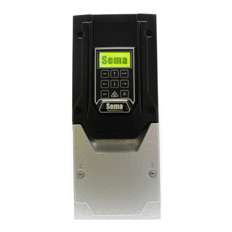
Seco DS9000 User manual

!"#$%&&%$!'"()('*+,%$!'"(-%".%&
#+/'0(%/(12345
1#6777(13
8
39:;(#<55=(/>?92>;;52

1
+"@!"++,!"@(/A%"@+#
!"#$%&'%( )*$+,%&+( %$-$%.$-( ,/$( %&0/,( ,'( 123$( $40&4$$%&40( %$5&4$1$4,-( '4( 2**( &,-( #%'6"+,-7( ( !"+/
%$5&4$1$4,-( 128( 255$+,( &45'%12,&'4( 0&.$4( &4( &4-,%"+,&'4-9( :/$%$5'%$9( .#+( '"&B( $A+( !"#$,./$!'"#
$A%$(%,+(*%/C+1(D!$A($A+(*,'1./$E
,+/',1('F(,+G!#!'"
;$.&-&'4 <2,$ <$-+%&#,&'4
= >?@AB@BC D%&0&42*(;$*$2-$
E ?A@?F@?? ;$.&-$(+'%#'%2,$(&6$4,&,87

2
TABLE OF CONTENTS
Description Page
1.0 INTRODUCTION AND PRODUCT DESCRIPTION ___________________________________ 4
1.1 General Information ________________________________________________________ 4
1.2 Digital Speed Controller _____________________________________________________ 4
1.3 Features __________________________________________________________________ 4
1.4 Specifications _____________________________________________________________ 4
1.5 Front Panel Controls _______________________________________________________ 5
1.7 Rear Panel Functions _______________________________________________________ 6
1.7.1 Dip Switch Functions _______________________________________________________ 6
1.7.2 Terminal Connection Points _________________________________________________ 7
1.8 System Parameters, Operational, Setup and Tune-up______________________________ 9
1.9 Modes of Operation _______________________________________________________ 10
1.9.1 Set-Point Controller _______________________________________________________ 10
1.9.2 Follower ________________________________________________________________ 11
2.0 DS9000 SYSTEM START-UP ______________________________________________________ 11
2.1 System Components _______________________________________________________ 11
2.2 Installation ______________________________________________________________ 12
2.2.1 DS9000 Mounting_________________________________________________________ 12
2.2.2 Ambient Temperature______________________________________________________ 12
2.2.3 Altitude _________________________________________________________________ 12
2.2.4 Air Contaminants _________________________________________________________ 13
2.2.5 Mounting Clearances ______________________________________________________ 13
2.2.6 Mounting Area ___________________________________________________________ 13
2.2.7 Ground Conductor ________________________________________________________ 13
2.2.8 Electrical Connections _____________________________________________________ 13
2.3 Installation Wiring ________________________________________________________ 13
2.3.1 Wiring Codes ____________________________________________________________ 13
2.3.2 Shielded Cable____________________________________________________________ 13
2.4 Wiring the System_________________________________________________________ 14
2.5 Starting the Drive _________________________________________________________ 14
2.6 Adding the DS9000________________________________________________________ 15
2.7 DS9000 Preliminary Set Up _________________________________________________ 23
2.7.1 Initial Settings for Switches _________________________________________________ 23
2.7.2.1 Set-Point Controller or Follower Mode________________________________________ 23
2.7.1.2 Closed Loop/Open Loop Select ______________________________________________ 23
2.7.1.3 Controlled Motor Feedback Signal ___________________________________________ 23
2.7.1.4 Reference Motor Feedback Signal ____________________________________________ 23
2.7.1.5 Tach Display Value ________________________________________________________ 23
2.7.1.6 Software Revision Number__________________________________________________ 24
2.7.2 Terminal Strip Connections _________________________________________________ 24
2.7.3 Set Up Adjustment Parameters_______________________________________________ 26
2.7.4 Scaling the Motor Speed, Open Loop Control __________________________________ 28
2.7.5 Closed Loop Speed Controller _______________________________________________ 28
3.0 OPERATING THE DS9000 AS A SET-POINT CONTROLLER __________________________ 28
3.1 RPM Programming/Readout_________________________________________________ 29
3.2 Engineering Units – Programming/Readout ____________________________________ 29
3.3 Starting and Stopping ______________________________________________________ 29
3.4 How to Set Speed _________________________________________________________ 30
3.5 How to Change Parameters _________________________________________________ 30
3.5.1 Security, Inhibiting Parameter Changes _______________________________________ 30
3.5.2 Parameter Changes with OFF _______________________________________________ 30
3.5.3 Parameter Changes with DS9000 Running _____________________________________ 30
3.6 Changing Parameter Data Tables (A or B) _____________________________________ 30

3
4.0 OPERATING THE DS9000 AS A FOLLOWER CONTROLLER__________________________ 31
4.1 How to Determine Your Ratio_______________________________________________ 31
4.2 RPM/Engineering Units ____________________________________________________ 34
4.3 Starting and Stopping ______________________________________________________ 35
4.4 Setting Your Ratio _________________________________________________________ 36
4.5 How to Change Parameters _________________________________________________ 36
4.5.1 Security, Inhibiting Parameter Changes _______________________________________ 36
4.5.2 Parameter Changes with DS9000 OFF ________________________________________ 36
4.5.3 Parameter Changes with DS9000 Running _____________________________________ 36
4.6 Changing Parameter Data Tables (A or B) _____________________________________ 36
5.0 TUNING YOUR SYSTEM_________________________________________________________ 37
5.1 Proportional Gain (Stability) ________________________________________________ 37
5.2 Integral Gain (Stability) ____________________________________________________ 37
5.3 Position Error Gain (Follower Mode) _________________________________________ 37
6.0 APPLICATIONS USING TWO OR MORE DS9000 UNITS _____________________________ 38
6.1 Parallel Connection _______________________________________________________ 38
6.2 Series Connection _________________________________________________________ 38
7.0 SYSTEM TROUBLESHOOTING ___________________________________________________ 38
7.1 Error Codes ______________________________________________________________ 38
7.2 Troubleshooting Tips ______________________________________________________ 39
7.2.1 System Troubleshooting____________________________________________________ 39
7.2.2 Terminal Strip Connections _________________________________________________ 39
7.2.3 Dipswitch Positions _______________________________________________________ 39
7.2.4 Data Parameters __________________________________________________________ 39
7.2.5 Voltage Checks ___________________________________________________________ 39
7.2.6 Pulse Train Input (Feedback and Reference Input) ______________________________ 40
7.2.7 Master Follower Operation _________________________________________________ 40
8.0 PARAMETER CODE/VALUE WORKSHEETS ________________________________________ 41
APPENDIX A – DS9000A INSTALLATION & OPERATING INSTRUCTIONS ________________ A1
FIGURES
Fig. 1 Connection Diagram________________________________________________________ 8
Fig. 2.1 Outline and Mounting Dimensions ___________________________________________ 12
Fig. 2.2 DS9000 Wiring Diagram as a Set-Point Speed Controller (Bronco II Series DC Motor
Controller) ______________________________________________________________ 15
Fig. 2.3 DS9000 Wiring Diagram as a Set-Point Speed Controller (SECO SE2000 Series DC
Non-Regenerative Drive) ___________________________________________________ 16
Fig. 2.4 DS9000 Wiring Diagram as a Set-Point Speed Controller (SECO SE2000 Series DC
Non-Regenerative Drive with Auto/Manual)____________________________________ 17
Fig. 2.5 DS9000 Wiring Diagram as a Set-Point Speed Controller (Q7000 Series DC Motor
Controller) ______________________________________________________________ 18
Fig. 2.6 DS9000 Wiring Diagram as a Set-Point Speed Controller (SECO M-3000 Series
DC Three Phase Drive)_____________________________________________________ 19
Fig. 2.7 DS9000 Wiring Diagram as a Set-Point Speed Controller (SECO VC55 AC Drive)_____ 20
Fig. 2.8 Ds9000 Wiring Diagram as a Set-Point Speed Controller (SECO CD 230V, 3Ø Drive)__ 21
Fig. 2.9 Connection Diagram for Various Pulse Generators ______________________________ 22
Fig. 4.1 Connection Diagram for Two DS9000 Controllers Used in a Master/Follower
Configuration ____________________________________________________________ 32

4
1.0 INTRODUCTION AND PRODUCT DESCRIPTION
1.1 GENERAL INFORMATION
This manual outlines installation and operating practices for the DS9000 series of Digital Speed
Controllers. It also contains a brief description of the product and includes specifications. Before
installing or operating the equipment, read and understand this manual.
1.2 DIGITAL SPEED CONTROLLER
The SECO DS9000 Digital Speed Controller is a closed loop digital speed regulator which can operate
as a Speed Set point controller or as a precision follower when used with an AC or DC drive. The
controller will maintain a long term speed accuracy of ±.01% of top speed and the 16-bit
microcontroller used in the unit provides a 10ms control loop update time, giving tight control and
good stability.
The DS9000 allows up to eight preset speeds and two sets of the following parameters, maximum
speed, minimum speed, acceleration time and deceleration time to be set by the user. Other
parameters such as scaling factors and stabilizing gains are also adjustable. An easy to read digital
readout shows speed in user selected engineering units. When used as a follower, the digital readout
will show the speed of the controlled motor or the speed of the reference.
The DS9000 will allow two complete sets of operator adjustments to be preset. This means the unit
can be set up to handle two different applications or products. Selection of the operating set of
parameters is by terminal strip connection at the rear of the unit.
The 0-10VDC output signal to the AC or DC drive being controlled is isolated from common on the
DS9000 and can be connected to non-isolated motor controllers.
DS9000 DIGITAL SPEED CONTROLLER
1.3 FEATURES
•Closed Loop Set Point Controller – long term accuracy ±.01% of top speed
•16 bit microprocessor controller
•Fast Response Time – internal up-date time 10 ms.
•Feedback Rate Programmable – 30 – 600 pulses per revolution
•Feedback Signal Selectable – Magnetic pick-up
Encoder
Open Collector Hall Effect type
•Speed Control or Follower Mode
•Readout of Speed in user selected Engineering Units or RPM
•Follower Mode speed readout displays controlled motor or reference signal
•Isolated output signal to AC or DC motor control, 0-10VDC, 5mA
•Speed setting resolution of 1 RPM
•Two selectable sets of independent parameters can be programmed
•Four Preset Speeds or Ratios within each set of parameters
•Speed or ratio may be changed while operating
1.4 SPECIFICATIONS
AC Supply 115/230VAC ±10%, 15VA
Ambient Temperature 0-50°C
Altitude 0-1000 M or 3300 ft.
Accuracy Speed holding ±1 RPM
Zero cumulative error in follower mode

5
Response 10 ms internal up-date time
Display 4 digit, .6”, RED L.E.D.
Feed back
Sensor 1) Magnetic pick-up (Seco MTK type)
2) Encoder
3) Open collector proximity switch
Input Frequency
Range Master Mode
Max. Frequency 25KHz, Min. Frequency 30Hz
Follower Mode
Max. Frequency 20KHz, Min. Frequency 50Hz
Mode Speed Set Point controller 0-1800 RPM
Follower – ratio adjustable 0-999.9% or equivalent.
Speed Range 35:1 with 60 ppr magnetic sensor on 1750 RPM motor
500:1 with 600 ppr Encoder on 1750 RPM motor
Inputs Feedback pulse train
Reference pulse train (Follower Mode only)
Start/Stop, 5-30V Isolated sink or source to Start
115V/230V AC 50/60 Hz 15VA
Security (prevents unauthorized parameter changes)
Speed/Ratio Parameter (selects one of four possible preset speeds or
ratios)
Parameter Data Table (selects one of two unique data tables, A or B)
Outputs Drives control signal 0-10V DC, (5mA max.), isolated from DS9000
common
Excessive following error indication for Follower Mode
+5VDC power supply for encoders (max current 40mA)
1.5 FRONT PANEL CONTROLS
The DS9000 Front Panel has a 4-digit LED readout, 6 keypad controls, and 4 LED status indicators.
The keypad controls are:
PROG – Selects Program Mode, allows adjustment of:
Operator Adjustments
4 Preset Speeds/Ratios
Minimum Speed
Maximum Speed
Acceleration Time
Deceleration Time
Set-Up Adjustments
Feedback resolution of controlled motor
Feedback resolution of reference signal (Follower Mode)
Readout Scale Factor and Decimal Point placement for
Controlled Motor
Readout Scale Factor and Decimal Point placement for
Reference Signal
Proportional Gain (Stability)
Integral Gain (Stability)
Position Error Gain (Follower Mode)
TACH/REF Selects display of either Tach signal or Reference Set-point while

6
running.
UP Increases speed or data values or scrolls up the Program parameters.
DOWN Decreases speed or data values or scrolls down the Program
parameters.
VALUE/CODE Changes display to either actual value of a parameter or parameter
name (used in Program Mode only)
HI/LOW Allows displayed value to be changed, either one count at a time
(LOW range) or 100 counts at a time (HI range) by the Up or Down
Arrow Key. In the Follower mode, the HI range changes the displayed
value by 10 counts at a time while running to allow for smaller
maximum incremental ratio changes.
LED DISPLAYS:
HI ADJ LED Indicates that HI/LOW key input is in High mode.
LOW ADJ LED Indicates that HI/LOW key input is in Low mode.
TACH LED Indicates that display is actual speed of controlled motor or reference
input.
Indicates Program mode when LED is blinking
REFERENCE LED Indicates that display is the speed set-point.
NOTE: The TACH and REFERENCE LED are only used while the Start input is on.
1.7 REAR PANEL FUNCTIONS
The rear panel of the DS9000 contains 3 terminal strips to which the connections are made and has a
number of DIP switches to allow various parameters to be set for a particular application.
1.7.1 DIP SWITCH POSITIONS
Switch Position Function
1 OFF – Setpoint Controller Mode
ON – Follower Mode
2 OFF – Enable PI and Position Control (Closed Loop Control)
ON – Disable PI Controller in Set Point Control Mode
(Scaled 0-10V for 0-1800 RPM)
ON – Disable Position Controller in Follower Mode*
3 Controlled Motor Feedback Type
OFF – Magnetic Pickup or Zero Cross Sensor
ON – Encoder or Open Collector (input impedance 3.3K)
4** Reference Motor Feedback Type
OFF – Magnetic or Zero Cross Sensor
ON – Encoder or Open Collector (input impedance 3.3K)
5** Tach Display Value (Enabled by Tach/Ref Key, applicable for follower
mode only)
OFF – Tach Shows Reference** RPM or Engineering Units
ON – Tach Shows Controlled Motors RPM or Engineering Units

7
6 OFF – Not used
ON – Displays DS9000 System revision number upon power up
Note: Switches 1, 3, 4 and 6 can only be changed when the DS9000 is not running, i.e. the START
input is not on.
* When used as a Follower Controller, Dip Switch #2 in the ON position will maintain closed loop
speed control loop speed control but will not maintain position synchronization of the Controlled
motor with the Master Reference.
** Follower Mode only
1.7.2 TERMINAL CONNECTION POINTS:
See Fig. 1 for connection information.
Connector Terminal Function
TB1 1 Start/Stop Input Common
2 Start/Stop Input (+5 to25VDC)
3 Open selects Parameter Data Table A. Connected to TB1-12 selects
Parameter Data Table B
4 Open selects Group A. Connected to TB1-12 selects Group B
5 Open selects PS1 in Group A or PS3 in Group B. Connected to
TB1-12, selects PS2 in Group A or PS4 in Group B
6 Open – Security Off. Connected to TB1-12 Security On
7 Open collector output for customer connection, signals “OPLP”
open loop error, signifies excessive following error in Follower
Mode (25V max., 50 mA sinking)
8 Controlled Motor Feedback Signal Input
9 Controlled Motor Feedback Signal Common
10 +5VDC (40mA max) source voltage for Encoder Feedback
11 Follower Reference Signal Input
12 Follower Reference Signal Common
TB2 1 AC Input
For 115 VAC Input:
Jumper TB2-1 to TB2-2
Jumper TB2-3 to TB2-4
For 230 VAC Input:
Jumper TB2-2 to TB2-3
TB2-1, TB2-4 Unused
6ACInput
TB3 1 Isolated Analog Reference Output 0-10V
2 Isolated Reference Common
Note: Do not connect the case ground to the reference common. There should be no connections
between terminal connection points TB-3 through TB1-12 and the motor controller (TB3-1 & 2). Use
isolated contacts (switches or relay contacts) to connect the appropriate terminal points to signal
common, TB1-9 or TB1-12.

8
Figure 1 – Connection Diagram

9
1.8 SYSTEM PARAMETERS, OPERATIONAL, SETUP AND TUNE-UP
The DS9000 allows the user to change or “program” eight Operational parameters in order to adjust
the control to the particular application. Of the additional nine parameters, six are explained in
sections 3.0 and 4.0 and the remaining three in section 5.0.
It is not necessary to go to PROG mode to change the currently selected active speed/ratio. When not
in PROG mode the current value is displayed and it may be changed simply by pushing the UP or
DOWN key.
The Operational parameters that can be changed while operating the unit are:
PS1 Preset Speed #1/ Preset Ratio #1 – Adjustable by UP and DOWN Arrow keys. Value limited by
HI and LOW values. Readout scaling set by SCFO and decimal point position set by SCDO. As
shipped the default value for speed ranges is 0-1800 (RPM).
PS2 Preset Speed #2/ Preset Ratio #2 – Adjustable by UP and DOWN Arrow keys. Value limited by
HI and LOW values. Readout scaling is the same as PS1.
PS3 Preset Speed #3/ Preset Ratio #3 – Adjustable by UP and DOWN Arrow keys. Value limited by
HI and LOW values. Readout scaling is the same as PS1.
PS4 Preset Speed #4/ Preset Ratio #4 – Adjustable by UP and DOWN Arrow keys. This preset
speed is not limited by Max;. Speed (HI) or Minimum Speed (LO) parameters. It can be set to
SCF0 (Max) or 0 (Min). Readout scaling is the same as PS1.
While in PROG mode the currently selected active speed/ratio will be indicated by a “-“ before its
corresponding number, example: “PS-2”. If the status of TB1-4 and 5 are changed while in PROG
Mode, the DS9000 will not recognize the change until you move out of PROG Mode.
PRESET SPEED/ RATIO SELECT TABLE
Terminal Strip Input Connections
Active
Parameter TB1-4 TB1-5 Group
PS1 OPEN OPEN A
PS2 TB1-12 OPEN A
PS3 OPEN TB1-12 B
PS4 TB1-12 TB1-12 B
TB1-9 and TB1-12 are both signal common and either one can be used as a tie point for signal
common.
Note: Depending on the Group selected, only two Speed or Ratio Parameters can be viewed, either
Group A, PS1 and PS2, or Group B, PS3 and PS4. To view the opposite set, make the
appropriate changes to the connection at TB1-5.
The setup parameters are similar to those that would be set via potentiometers or jumpers on an
analog device. These are set at start up and usually do not need to be changed unless the process to be
performed changes.

10
LO Minimum Speed setting – Adjustable by UP and DOWN Arrow keys. Readout scaling is the
same as PS1 – PS4. In set point mode, the maximum value that can be set is 1/3 of scale factor
SCF0. In the follower mode, the maximum “LO” value is (HI - .001). Minimum value that can
be set in either mode is 0.
HI Maximum speed setting. Adjustable by UP and DOWN Arrow keys. Readout scaling is the
same as PS1 – PS4. Value is limited by SCF0 (max) and 2/3 of SCF0 (min) in set point mode.
In follower mode, the maximum value is 9.999 and the minimum value is (LO + .001).
ACE1 Time in seconds to accelerated from zero to full speed. Adjustable by UP and DOWN Arrow
keys between 0.1 and 999.9 seconds. This parameter is not displayed in follower mode.
dEC1 Time in seconds to decelerate from maximum speed to zero speed. Adjustable by UP and
DOWN Arrow keys between 0.1 and 999.9 seconds. This parameter is not displayed in
follower mode.
FEd0 Feedback resolution for the controlled motor is equal to the maximum feedback frequency
divided by 30. The maximum value is 600 and the minimum is 30.
FEd1 The same as FEd0 except for the master reference input used when in follower mode. Not
displayed in setpoint mode.
SCF0 Scale factor for readout of controlled motor. Enter the value you wish to have displayed at
maximum speed. If RPM, and maximum speed is 1800 RPM, enter 1800.
SCF1 Same as SCF0 except for the reference signal input. Enter value to displayed at maximum
reference input frequency. Not displayed in setpoint mode.
SCd0 Decimal point location for SCF0
SCd1 Decimal point location for SCF1. Not displayed in setpoint mode.
The tune-up parameters are used for the few applications where modifications to the system gain
parameters are required. The default values will be acceptable for most applications. For all three gain
parameters, to increase the gain decrease the value entered (50 – maximum gain for PE and IE, 5 for
POSE). See Section 5.0 for detailed instructions.
PE Proportional gain adjustment. The default value is 200. The range of adjustment is 50 to 300.
IE Integral gain adjustment. The default value is 300. The range of adjustment is 50 to 2000.
POSE Position error gain adjustment. This parameter is only applicable in the follower mode. The
default value is 10. The range of adjustment is 5 to 300.
1.9 MODES OF OPERATION
1.9.1 SET-POINT CONTROLLER
In the Set-Point Controller Mode the speed set-point for the controlled motor is entered by the
operator on the key pad and displayed on the 4-digit display. The DS9000 compares this set-point
with the signal from the feedback pulse generator and provides a control signal to the drive to reduce
the error to zero.

11
1.9.2 FOLLOWER
In the Follower mode the set-point is calculated by multiplying the Follower reference frequency
signal by a ratio entered on the DS9000 keypad by the operator.
Example:
Reference input 1800 RPM with 60 PPR generator
Ratio 0.500
Set-point is 900 RPM
As happens in the Set-Point control Mode the DS9000 compares the Set-point signal with the
feedback signal and provides an analog output to the ac or dc drives so as to reduce the speed error to
zero. In the Follower mode the DS9000 will bring the pulses on the output shaft into synchronization
with the pulses of the Follower reference thus providing a “position lock” on the two shafts. If the
ratio is changed while running the position counters are set to zero and synchronization will restart at
that point.
2.0 DS9000 SYSTEM START-UP
2.1 SYSTEM COMPONENTS
A complete DS9000 drive system consists of:
DS9000 Digital Speed Controller
AC or DC Adjustable Speed Drive
AC or DC Motor with Pulse generator mounted
The AC or DC drive must be able to be controlled by a 0-10VDC input signal and must be fully
operational and capable of driving the connected load at the correct speed. The AC or DC motor
controlled by the drive must be fully operational and have a Pulse Generator mounted on it. The pulse
generator can be a Magnetic Pick-up (Seco MTK type) or Encoder or Hall Effect device.
2.2 INSTALLATION
The procedure describes the installation of the DS9000 controller.
Caution
In cases where the digital speed controller is integrated into a customer-designed drive system, the
buyer is responsible for the correct choice of required associated equipment. Incorrectly specified
components may cause improper operation and/or damage to the digital speed controller.
Warning
Only qualified maintenance personnel should install the controller. They should be familiar with
drive systems – including operation – and with the possible hazards resulting from improper
installation practices. Serious personal injury and/or equipment damage could result if this warning is
not observed.
Danger
The user is responsible for installation for the entire drive system in accordance with NFPA No. 70;
with Electrical Standards for Metal-working Machine Tools, NFPA No. 70; and with all local and
national codes which apply. Serious personal injury, death and /or equipment damage could result if
this procedure is not followed.

12
2.2.1 DS9000 MOUNTING
The DS9000 controller should be flange mounted to a panel in a horizontal position. Drill patterns
and dimensions for the DS9000 controller are shown in Figure 2-1. Be certain that the mounting area
provides the environmental conditions noted in the following paragraphs.
To mount the DS9000 in your panel, follow these steps:
1. Cut out the mounting hole for the DS9000 as shown in the panel cutout dimensions in Fig. 2.1.
2. Remove the two socket head screws in the back of the DS9000 with a 1/16” hex wrench.
3. Remove the two slides from each side of the DS9000.
4. Slide the DS9000 through the front of the panel cutout.
5. Replace the two slides on each side of the DS9000.
6. Replace and tighten the two socket head screws.
2.2.2 AMBIENT TEMPERATURE
Ambient temperature should not exceed 50°C for chassis mount unit.
2.2.3 ALTITUDE
Altitude should not exceed 1000 meters (3300 feet). Consult factory for de-rating factor for high
altitude operation.
Fig. 2.1
Outline and Mounting Dimensions

13
2.2.4 AIR CONTAMINANTS
Ambient air should not be contaminated with caustic chemical vapors, excessive dust, dirt or
moisture. If such conditions exist, the proper enclosure and cooling methods recommended for such
conditions should be used.
2.2.5 MOUNTING CLEARANCES
Adequate clearance should be allowed for easy access to terminals and adjustments and to facilitate
inspection and maintenance.
2.2.6 MOUNTING AREA
Mounting area should be free of vibration and have sufficient clear air circulation.
2.2.7 GROUND CONDUCTOR
An equipment ground conductor (that is, ground wire) must be connected to the controller case. This
conductor must run unbroken to a drive system wire connection point – or ground bus or grounding
terminal block, as local usage determines. Separate equipment grounding conductors from other
major components in the system must also be run unbroken to a central connection point. These
components include:
•Motor
•Isolation transformer case, if used
•Operator control panel and enclosure, if used.
•DS9000
•AC or DC Drive
2.2.8 ELECTRICAL CONNECTIONS
When connecting the equipment grounding conductor to the DS9000 controller case, permanently
connect it to the grounding terminal provided.
2.3 INSTALLATION WIRING
Be sure that the AC power supplied is the voltage and frequency called for on the controller name
plate. Improper voltage may damage the equipment and insufficient current will cause erratic
operation of the controller. Typical connection diagrams are shown in Figures 2.2 and 2.3.
2.3.1 WIRING CODES
All interconnection wiring should be installed in conformance with the National Electrical Code
published by the National Fire Protection Association as well as any other applicable local codes.
2.3.2 SHIELDED CABLE
Shielded cable is required for the pulse generator, and all low-level signal circuits to eliminate the
possibility of electrical interference. Connect the shield to chassis ground at the controller end of the
cable only. There should not be any connections between the DS9000 signal common and any other
ground or common.

14
2.4 WIRING THE SYSTEM
Connect the AC or DC drive in accordance with the manufacturer’s instructions. Connections for
SECO drives are shown in Figures 2.2 thru 2.8.
Connect the DS9000 as shown in Fig 1. Note it is important that the DS9000 Run signal is activated at
the same time the drive is started.
2.4.1 RECOMMENDED WIRING PROCEDURES
1. A proper Earth Ground connection should be installed to all specified points on the control.
The Earth Ground should be a low impedance wire connection installed in accordance with
the NEC Article 250. Mechanical grounding using conduit, etc., may not provide proper
grounding against high frequency Electromagnetic Interference (EMI).
The connected Earth Ground should be free of all high frequency electrical noise such as
spikes and notches generated by SCR motor drives.
The controller signal (circuit) common should not be tied to the Earth Ground connection
unless explicitly specified.
2. Physically separate all control signal wiring from all power wiring such as 120 VAC, 240 VAC,
etc. line power, motor armature and field wires. Do not place control signal wiring and power
wiring together in conduit or wire raceways. Cross control signal and power wiring at right
angles if necessary.
Control signal wiring should also be physically separated from all radiated noise sources such
as motors, relays, contactors, solenoids, etc..
3. Use shielded and twisted pair wiring on all control signal wiring. This will increase immunity
to both electric field and magnetic field noise.
The shield should be terminated to chassis or earth ground at one end only (preferably at the
controller). Terminating both ends of the shield can create ground loops.
4. Place a Resistor/Capacitor network on all relay, contactor and solenoid coils that are on the
same AC power or physically located near the controller. R/C networks with capacitors of 0.1
micro farads (600 VDC/250 VAC) and resistors of 100 ohms (1/2 watt) are recommended.
2.5 STARTING THE DRIVE
Install and start-up the DC or AC drive being used with the DS9000 in accordance with the
manufacturers instructions. Make sure the motor shaft is free to rotate and that the magnetic pick-up
or encoder or pulse generator is correctly installed. The feedback signal is to be connected only to the
DS9000 and not to the DC or AC drive. The drive should be setup to run in “Armature Feedback”
mode. Refer to the Drive Instruction Manual for the proper procedure to do this.
Make sure the AC or DC drive can be controlled manually using a speed potentiometer connected to
signal input terminals. Set all preset adjustments to the correct value and ensure that acceleration and
deceleration controls are set at the minimum values (System acceleration and deceleration will be set
by the DS9000). If the drive can be set-up to by-pass the acceleration and deceleration circuits, such
as the SECO Q7000 accel jumper, adjust the drive accordingly. Set the IR Comp adjustment to
minimum (usually full CCW on the IR Comp potentiometer). Turn off AC power to the motor
controller.

15
2.6 ADDING THE DS9000
The DS9000 provides a signal that replaces the signal usually obtained from the speed potentiometer
on the drive to be controlled.
The control signal from the DS9000 is isolated from ground and common on the DS9000 and the
signal may be connected to non-isolated drives.
Figure 2.2
DS9000 Wiring Diagram as a setpoint speed controller
(BRONCO II Series DC motor controller)

16
Figure 2.3
DS9000 Wiring Diagram as a Setpoint Speed Controller
(SECO SE2000 DC Non-Regenerative Drive)

17
Figure 2.4
DS9000 Wiring Diagram as a Setpoint Speed Controller
(SECO SE2000 DC Non-Regenerative Drive With Auto/Manual)

18
Figure 2.5
DS9000 Wiring Diagram as a Setpoint Speed Controller
(Q7000 Series DC Motor Controller)

19
Figure 2.6
DS9000 Wiring Diagram as a Setpoint Speed Controller
(SECO M3000 DC Three Phase Drive)
This manual suits for next models
1
Table of contents
Other Seco Controllers manuals
Popular Controllers manuals by other brands
Aerotech
Aerotech UNIDEX U100i Operation & technical manual
NSI
NSI MC 6300 Operation manual
LAMBERTI ELEKTRONIK
LAMBERTI ELEKTRONIK Latherm HZR Comfort operating manual
Ramix
Ramix PMC422 Hardware reference manual
KMC Controls
KMC Controls MCP-1040 Series installation guide

Emerson
Emerson Fisher 1301 Series manual

