Seco SE 2000 Series User manual

SECO
®
SE 2000 Series DC Motor Controller
1 Through 5 HP
115/230 VAC 1 Phase Input
Installation
&
Operation Manual

2
TABLE OF CONTENTS
Section Page
1.0 GENERAL INFORMATION ................. 3
1.1 Controller ............................................. 4
1.2 Specifications ...................................... 7
2.0 INSTALLATION ................................... 8
2.1 Power Unit Models ............................... 8
2.2 Controller Mounting .............................. 9
2.2.1 Ambient Temperature ........................... 9
2.2.2 Altitude ................................................. 9
2.2.3 Air Contaminants .................................. 9
2.2.4 Mounting Clearances............................ 17
2.2.5 Mounting Area ...................................... 17
2.2.6 Ground Conductor ................................ 17
2.2.7 Electrical Connections .......................... 17
2.3 Installation Wiring ................................. 17
2.3.1 Wiring Codes ........................................ 17
2.3.2 Shielded Cable ..................................... 17
2.3.3 Motor Shunt Field ................................. 17
2.3.4 Permanent Magnet Motors ................... 21
2.3.5 Motor Series Field ................................ 21
2.3.6 Motor Thermostat ................................. 21
3.0 OPERATION ....................................... 21
3.0.1 Speed Adjust Potentiometer ................ 21
3.0.2 Torque Adjust Potentiometer ............... 21
3.0.3 Start/Stop ............................................ 21
3.0.4 Jog/Run ............................................... 21
3.0.5 Forward/Reverse................................. 21
3.1 Initial Settings ...................................... 21
3.1.1 Line Voltage Selection ......................... 22
3.1.2 A.C. Supply ......................................... 22
3.1.3 Voltage Feedback ............................... 22
3.1.4 Current Scaling .................................... 22
3.1.5 Speed Feedback Selection .................. 22
3.1.6 Field Failure Circuit.............................. 22
3.1.7 Overcurrent Trip Circuit ....................... 22
3.1.8 Torque vs. Speed Control.................... 22
3.1.9 Maximum Speed ................................. 22
3.1.9.1 Minimum Speed .................................. 22
3.1.9.2 Acceleration/Deceleration Times ......... 23
3.1.9.3 IR Compensation ................................. 23
3.1.9.4 Jog....................................................... 23
3.1.9.5 Torque (current limit) and Slope .......... 23
3.2 Indicators ............................................. 23
4.0 RELAY CIRCUITS .............................. 24
4.1 Power Unit and Basic On-Off .............. 24
4.2 Run-Brake ........................................... 24
4.3 Reversing Brake .................................. 24
4.4 Jog....................................................... 24
4.5 Alternative Start/Stop Control
Arrangements ...................................... 24
Section Page
5.0 OPTIONS ........................................... 33
5.1 General Description ............................ 33
5.1.1 Option Description .............................. 33
6.0 START UP PROCEDURES ............... 34
6.1 Field Excitation ................................... 34
6.2 Control Voltage ................................... 34
6.3 Motor Rotation and Tachometer
Generator Feedback ........................... 34
6.4 Speed Setting Adjustment .................. 34
6.5 Loading ............................................... 34
6.6 Option Installation and Start-Up ......... 35
6.7 Follower-Process Controller/
DC Voltage ........................................ 35
6.7.1 Specifications ..................................... 35
6.7.2 Input Connections .............................. 35
6.7.3 Jumper/Switch Selection .................... 35
6.7.4 Adjustments ........................................ 35
6.8 Follower-Pulse Tach Generator ...... 35
6.8.1 Specifications ..................................... 35
6.8.2 Input Connections .............................. 36
6.8.3 Adjustments ........................................ 36
6.9 Controller Deceleration Stop ........... 36
6.9.1 Specifications ..................................... 36
6.9.2 Connections ....................................... 37
6.10 Fault Module ..................................... 37
6.10.1 Specifications ..................................... 37
6.10.2 Connections ....................................... 37
6.10.3 Adjustments ........................................ 37
6.11 Enhanced Torque Slope .................. 37
6.11.1 Features ............................................. 37
6.11.2 Adjustment of SE2000 Drive .............. 37
6.11.3 Adjustment Procedure with Line Speed
Signal ................................................. 38
6.11.4 Adjustment Procedure without Line Speed
Signal ................................................. 38
7.0 THEORY OF OPERATION ................. 39
7.1 Drive System ....................................... 39
7.2 Control Electronics .............................. 39
7.3 Basic Block .......................................... 39
7.3.1 Speed Reference ................................ 39
7.3.2 Process Follower Buffer ...................... 39
7.3.3 Acceleration/Deceleration .................... 39
7.3.4 Tach Scaling Circuit............................. 39
7.3.5 Armature Voltage Scaling .................... 39
7.3.6 Speed Loop Regulator and
IR Comp .............................................. 39
7.3.7 Current Regulator ................................ 39
7.3.8 Firing Circuits ...................................... 39

3
Section Page
8.0 TROUBLESHOOTING ........................ 45
8.1 Safety Procedures ............................... 45
8.2 Recommended Instruments ................ 45
8.3 Troubleshooting Areas ........................ 46
8.3.1 Loose Connections .............................. 46
8.3.2 Wiring Errors ....................................... 46
83.3 Incoming AC Line ................................ 46
8.3.4 Motor Checks ...................................... 46
8.4 Checking with External Meter .............. 46
8.4.1 Voltage Checks ................................... 47
8.5 Troubleshooting Guide ........................ 47
9.0 REPLACEMENT PARTS .................... 48
DANGER
The National Electrical Code (Publication
NFPA No. 70) requires that a fused main
disconnect switch be installed between the
AC line and the drive system or, if used, the
power transformer. (Specifically, this in-
cludes the Controller.) Serious injury or
death may result if a disconnect switch is
not provided.
DANGER
The main power feed must be disconnected
by a switch before it is safe to work on the
SE2000 internal parts. Serious personal
injury or death may result if the procedure
is not observed.
DANGER
The SE2000 unit is combined with user
components to form a drive package. The
user is responsible for proper selection of
parts and subsequent operation. When a
SE2000 Controller is being used, it should
be installed, adjusted and serviced only by
qualified personnel who are familiar with
the operation of all major components in
the system. Serious personal injury or
death, and/or equipment damage, may re-
sult if this procedure is not followed.
For your safety and for proper operation, please take
time to carefully read all instructions before installing
and operating this unit.
RECEIPT OF SHIPMENT
All equipment is tested before shipment, and is shipped
in good condition. Any damages or shortages evident
when the equipment is received must be immediately
reported to the commercial carrier who transported the
equipment. If required, assistance is available from the
nearest SECO AC/DC Drive Representative. Always
refer to SECO order number, model number and
serial number when contacting SECO AC/DC Drives.
NOTE: The information contained herein is accurate at
the time of publication. SECO AC/DC Drives reserves
the right to make design changes to motor controls
described in this manual at any time and without notice.
1.0 GENERAL INFORMATION
This manual outlines installation and operating prac-
tices for the SE2000 Series of DC controllers. It also
contains a brief description of the product and includes
specifications. Before installing or operating the equip-
ment, read and understand this manual. Always ob-
serve the following dangers and cautions when operat-
ing or working on this equipment.

4
1.1 CONTROLLER
SECO Drives SE2000 series DC motor controllers are
designed to control shunt wound and permanent
magnet DC motors from 1/4 to 5 HP. Versatile and
extremely reliable, the SE2000 is available in several
configurations to meet the needs of the most demanding
applications.
Design Features
• Full wave power conversion circuit with two SCR's
and three diodes providing NEMA Code K, DC arma-
ture supply insures optimum motor performance,
cooler motor operation and longer life.
•Circuit Protection
Transient voltage protection by MOV. All models
except Power Unit have AC line circuit breaker for line
protection.
•Enclosed Unit
Dead front and back construction. Hinged cover
provides easy access to all components.
•Isolation
Control circuit is isolated from main circuit potential.
•Tachometer Generator Feedback
For improved speed holding, unit will accept feed-
back from analog tach generator or digital pulse tach
generator.
•Jog
Jog at separately adjustable speed standard.
Adjustments
Customer adjustments match control to application.
•Maximum Speed
Limits speed available to operator
•Minimum Speed
Allows minimum motor speed to be set
•IR Compensation
Improves motor speed regulation in armature feed-
back mode
•Acceleration
Sets time to reach full speed
•Deceleration
Sets time to decelerate to zero speed
•Torque
Sets motor torque available (current limit)
•Slope
Produces increasing torque as speed decreases
•Jog
Sets separate Jog speed
•Torque and Slope Control
Precise setting of motor torque and slope control to
give increasing torque/decreasing speed character-
istic above fixed torque limit for simple winder appli-
cations.
•Control relay with three wire Start/Stop circuit. All
models have control relay to prevent automatic re-
start after power outage for increased safety (may be
reconnected for line start operation, if required.
•Field Supply with Field Loss Circuit standard.
•Overcurrent Protection
Timed overcurrent trip circuit for motor protection.
•Run-Brake Model
Unit includes motor contactor and dynamic braking.
•Reversing-Brake
Reversing model with dynamic braking
•4-20 mA or 0-10 VDC speed reference.
Selectable Features
Selected by jumpers which program drives for specific
motor or application.
•AC Supply
Selects 115 or 230 VAC
•DC Armature
Selects 90 or 180 VDC
•Feedback
Selects type and feedback value
•Preset Jog
Selects internal or external jog
•Field Loss
Selects for PM or shunt wound type motors
•Current Scaling
Selects appropriate motor amps
•Acceleration/Deceleration Time
Selects range of adjustment control up to 30 seconds
•Torque or Speed Control
Selects mode or either motor speed or motor torque
controlled by operator's potentiometer
•Overcurrent Trip
Timed or instantaneous or disabled

5
MODELS
•Power Unit Only
Consists of control board, SCR power bridge, and
terminals.
•Basic On-Off
Power Unit with single pole AC line circuit breaker.
Two pole breaker is standard on all 3-5 HP models
and all enclosed models.
•Run-Brake Model
Models include motor contactor and dynamic brak-
ing.
•Reversing-Brake
Models include forward and reversing contactors
with antiplugging and dynamic braking.
OPTIONS
•2 Pole Circuit Breaker
Enables both input lines to be disconnected. Re-
quired by some local Electrical Codes (std. on 3 & 5
HP models and on all enclosed units).
•Enhanced Process Follower
Speed control by external signal, 4-20 mA, 10-50
mA, 0-14 VDC, 0-100 VDC
•Digital Signal Follower
Speed control by external digital pulse signal from
MTK magnetic pick-up, Hall Effect sensor or en-
coder.
•Controlled Deceleration Stop
Drive follows deceleration ramp on Stop command.
Two stopping modes are available
RamporDynamicBrakingifadditionalStopbuttonis
used.
•Fault Module
Shuts down drive and provides output signal if Tach
Loss, Field Loss or Overcurrent failures occur.
SELECTION CHART
BASIC ON-OFF RUN-BRAKE REV-BRAKE
Input Power NEMA 4/12 NEMA 4/12 NEMA 4/12 NEMA 4/12 NEMA 4/12 NEMA 4/12
Line Unit W/O With W/O With W/O With
Voltage HP Only Chassis Operators Operators Chassis Operators Operators Chassis Operators Operators
115VAC 1/4-1
1 Phase SE2002 SE2102 SE2122 SE2132 SE2202 SE2222 SE2232 SE2302 SE2322 SE2342
230VAC 1/2-2
230VAC
1 Phase 3-5 SE2005 SE2105 SE2125 SE2135 SE2205 SE2225 SE2235 SE2305 SE2325 SE2345

6
OPTIONS
Factory Installed Field Installed
Description Model Number Suffix Model Number
2 pole circuit breaker – enables both lines to be
disconnected – required by some local electrical codes -1* SE2999-1*
Follower-Process Controller/DC Voltage Speed Control
by external signal, 4-20 mA, 1-5 mA, 0-14 VDC, 0-100 VDC -2** SE2999-2**
Follower-Pulse Tach-Generator-Speed Control by external
digital pulse signal from magnetic pick-up Hall Effect sensor
or encoder -3** SE2999-3**
Controlled Decel Stop-Drive follows deceleration ramp on
stop command -4** SE2999-4**
Fault module-shuts down drive and provides output
signal if tach loss, field loss or overcurrent failure occur -5** SE2999-5**
Enhanced Performance Torque-Slope External Control for
constant tension centerwind or external torque slope applications -6** SE2999-6**
* This option only applies to 2 HP chassis models.
** Any two of these options may be fitted to any unit, except power unt.
Models without local operators are designed to be integrated into a drive system and wired by the user. As such
it will be necessary to provide either a number of operator's controls or equivalent relay contacts. The control
functions are:
• Speed adjust or torque control potentiometer
• Start pushbutton switch, or relay contact
• Stop pushbutton switch, or relay contact
• Jog switch or relay contacts
• Forward/Reverse pushbutton, switch or relay contacts
• Automatic/manual switch or relay contacts

7
1.2 SPECIFICATIONS
Performance Characteristics
Speed Range: 30:1
Speed Regulation (As % of Motor Base Speed) –
For 95% Load Change
Armature Voltage Feedback: ±2%
Tachometer Feedback: ±1/2% (depending on tach generator)
Acceleration/Deceleration
Range A by current limit
Range B 3-30 seconds
Range C 0.3-3 seconds
Operating Conditions
Ambient Temperature –
Chassis Models: 55°C
Enclosed Models: 40°C
Relative Humidity: 95% Non-Condensing
Altitude: To 3300 Feet (1000m)
Adjustments
Current Range (Torque): 25-150%
Maximum Speed: 60-110% of Motor Base Speed
Minimum Speed: 0-30% of Motor Base Speed
IR Compensation: Improves load regulation in armature feedback mode
Acceleration: 0.3 to 30 Seconds
Deceleration: 0.3 to 30 Seconds
Preset Jog: 0-100% of Motor Base Speed
Torque Slope: Increasing torque to decreasing speed relationship
above a fixed torque limit
Ratings
Horsepower Range
115 VAC 1/4 - 1 HP
230 VAC 1/2 - 5 HP
AC Line Input Voltage: 115 or 230 V ±10%
AC Line Frequency: 50/60 Hz ±2 Hz, Single Phase
DC Output Voltage
115 VAC Supply
Armature: 0 - 90 VDC
Field: 50/100 VDC
230 VAC Supply
Armature: 0 - 180 VDC
Field: 100/200 VDC
Service Factor: 1.0
Duty: Continuous
Max. Load Capacity: 150% for 1 minute
Line Protection: Circuit Breaker (not Power Unit)
Speed Reference Signal Voltage: 0 - 10 VDC
4 - 20 mA Grounded or Ungrounded
Feedback Signal: 0 -14 VDC from 7V/1000 Tach Generator
0 - 85 VDC from 50V/1000 Tach Generator
60 PPR from MTK Magnetic Pickup

8
2.0 INSTALLATION
TheproceduredescribestheinstallationoftheSE2000
controller.
CAUTION
In cases where the motor speed controller is
integrated into a customer-designed drive
system, the buyer is responsible for the cor-
rect choice of required associated equip-
ment.Incorrectlyspecifiedcomponentsmay
cause improper operation and/or damage to
the motor speed controller.
WARNING
Onlyqualifiedmaintenancepersonnelshould
installthecontroller. Theyshouldbe familiar
with drive systems — including operation —
andwith the possiblehazards resultingfrom
improper installation practices. Serious per-
sonalinjuryand/orequipmentdamagecould
result if this warning is not observed.
DANGER
Theuserisresponsibleforinstallationforthe
entiredrivesysteminaccordancewithNFPA
No. 70; with Electrical Standards for Metal-
working Machine Tools, NFPA No. 70; and
withalllocalandnationalcodeswhichapply.
Serious personal injury, death and/or equip-
mentdamagecouldresultifthisprocedureis
not followed.
2.1 POWER UNIT MODELS
The Power Unit is intended to replace the Challenger
8500, 8600 and 8800 Power Units. The mounting
dimensions are identical to the Challenger Series.
Care should be taken to ensure the correct voltage
settings are selected for the SE2000 depending on
which Challenger Model is being replaced.
AjumperisinstalledonSE2002andSE2005modelsto
match the characteristics of the Challenger Series of
drives.
2.1.1 SE2000 STAND ALONE
If the SE2002 or SE2005 Control is to be used as a
stand along unit, remove the jumper that is connected
between pins 16 and 20 of connector P1. (Ref. Figure
1)
2.1.2 SE2000 POWER UNIT CONVERSION
If the SE2000 power unit is used on a C8000 series
assembly, use the chart below for the proper wire
reconnection. The factory installed wire jumper from
TB2-1 to TB2-3 must be removed and replaced with a
wire from TB2-1 to TB2-6.
From To
8500/8600 Model SE2002
TB1-1 C8501 TB1-L1
TB1-2 C8601 TB1-L2
TB1-1 C8503 TB1-L1
TB1-2 C8603 TB1-L2
TB1-3 TB1-A1
TB1-4, 5 or 6 TB1-A2
TB2-12* TB2-13
TB2-13 TB2-4
TB2-18 TB2-11
TB2-19 TB2-10
TB1-1 C8504 TB1-L1
TB1-2 C8604 TB1-L2
TB1-3 TB1-A1
TB1-4, 5 or 6 TB1-A2
TB2-12 TB2-4
TB2-13 TB2-13
TB1-1 C8509 TB1-L1
TB1-2 C8609 TB1-L2
TB1-3 TB1-A1
TB1-4, 5 or 6 TB1-A2
TB2-10* TB2-17
TB2-12* TB2-13
TB2-13 TB2-4
(Continued on next page)
Figure 1

9
From To
8300/8800 Model SE2005
TB1-1 C8301 TB1A-AC1
TB1-2 C8801 TB1A-AC2
TB1-1 C8303 TB1A-AC1
TB1-2 C8803 TB1A-AC2
TB1-3 TB1A-A1
TB1-4 or 5 TB1A-A2
TB2-12* TB2-13
TB2-13* TB2-4
TB2-18 TB2-11
TB2-19 TB2-10
TB1-1 C8304 TB1A-AC1
TB1-2 C8804 TB1A-AC2
TB1-3 TB1A-A1
TB1-4 or 5 TB1A-A2
TB2-12 TB2-4
TB2-13 TB2-13
TB1-1 C8309 TB1A-AC1
TB1-2 C8809 TB1A-AC2
TB1-3 TB1A-A1
TB1-4 or 5 TB1A-A2
TB2-12 Orange TB2-13
TB2-10 Brown TB2-17
TB2-12 Red TB2-4
TB2-13 Green TB2-13
* Wire extension may be required.
2.2 CONTROLLER MOUNTING
The SE2000 controller must be mounted in a vertical
position.Thisorientationpermitstherequiredcoolingof
the heat sinks.
Drillpatternsand dimensionsforthe SE2000 controller
are shown in Figure 2-1. Be certain that the mounting
areaprovidestheenvironmentalconditionsnotedinthe
following paragraphs.
2.2.1 AMBIENT TEMPERATURE
Ambient temperature should not exceed 40°C for en-
closed models or 55°C for chassis mount unit.
2.2.2 ALTITUDE
Altitude should not exceed 1000 meters (3300 feet).
Consult factory for de-rating factor for high altitude
operation.
2.2.3 AIR CONTAMINANTS
Ambient air should not be contaminated with caustic
chemical vapors, excessive dust, dirt, or moisture. If
suchconditionsexist,theproperenclosureandcooling
methods recommended for such conditions should be
used.

10
SE2000 Chassis
BasisON-Offor RunBrakeModels
Reversing Brake Models
SE2000 Power Unit
Enclosed Unit - All Models

11
Dimensionsininches
SE2000
1/4 - 2 HP Power Unit Layout

12
Dimensionsininches
SE2000
1/4 - 2 HP Chassis Layout
BasicOnOff
Run Brake
Rev Brake

13
SE2000
1/4 - 2 HP Enclosed Layout
BasicOnOff
Run Brake
Rev Brake

14
SE2000
3-5 HP Power Unit Layout
DimensionsinInches

15
SE2000
3-5HPChassisLayout
Basic On Off
Run Brake
Rev Brake
Dimensionsininches

16
SE2000
3-5HPEnclosed Layout
Basic On Off
Run Brake
Rev Brake
Dimensionsininches

17
2.3.3 MOTOR SHUNT FIELD
SE2000 controllers have a standard field voltage sup-
ply as follows:
115 VAC Controller 50/100 VDC Shunt Field Supply
230VACController100/200VDCShuntFieldSupply
Some motors are furnished with dual voltage fields. If
so,theywill have4fieldleadsmarkedF1,F2,F3(F11),
and F4 (or F22). In such instances, check the motor
nameplate for the field voltages and connect the motor
leads for the field voltage supplied by the drive. See
Figure 2-3 for various ways to connect the field supply
to wound field motors.TABLE 2
Typical
Motor Armature Line Recommended
Motor Voltage Current Current Transformer
HP (V dc) (A dc) (Arms) Rating KVA
1/4 90 3.0 5 1/2
1/2 90 5.5 9 1
1/2 180 2.8 5 1
3/4 90 8.4 13 1.5
3/4 180 4.0 7 1.5
1 90 10.7 16 2
1 180 5.3 8 2
1 1/2 180 7.7 12 3
2 180 9.5 14 5
3 180 14.5 21 7.5
5 180 23.4 34 10
SE2000
2.2.4 MOUNTING CLEARANCES
Adequateclearanceshouldbeallowedforeasyaccess
toterminalsandadjustmentsandtofacilitateinspection
and maintenance.
2.2.5 MOUNTING AREA
Mounting area should be free of vibration and have
sufficient clear air circulation.
2.2.6 GROUND CONDUCTOR
An equipment ground conductor (that is, ground wire)
must be connected to the controller mounting panel.
This conductor must run unbroken to a drive system
wire connection point — or ground bus or grounding
terminal block, as local usage determines. (See Figure
2-2) Separate equipment grounding conductors from
othermajorcomponentsinthesystemmustalsoberun
unbroken to a central connection point. These compo-
nents include:
• Motor
• Isolation transformer case, if used
• Operator control panel and enclosure, if used.
2.2.7 ELECTRICAL CONNECTIONS
When connecting the equipment grounding conductor
to the SE2000 controller mounting panel, permanently
connect it to the grounding terminal provided.
2.3 INSTALLATION WIRING
Be sure that the AC power supplied is the voltage and
frequency called for on the controller nameplate. Also
be sure that the power line is capable of supplying the
KVA rating indicated on Table 2 without voltage reduc-
tion.Impropervoltagemaydamagetheequipmentand
insufficient current will cause erratic operation of the
drive.TypicalconnectiondiagramsareshowninFigure
2-2.
On enclosed units, install conduit fittings that maintain
the NEMA integrity of the enclosure.
2.3.1 WIRING CODES
All interconnection wiring should be installed in con-
formance with the National Electrical Code published
by the National Fire Protection Association as well as
any other applicable local codes.
2.3.2 SHIELDED CABLE
Shielded cable is required for the tachometer genera-
tor, speed potentiometer, and all low-level signal cir-
cuits to eliminate the possibility of electrical interfer-
ence. Connect the shield to chassis ground at the
controller end of the cable only.
CAUTION
Follow the installation wiring diagram pro-
vided in Figures 4-1 to 9. When connecting
the motor, pay particular attention to the
marking on the motor leads. It is possible to
damagethe Controller andmotor if incorrect
connections are made.

18
Figure 2-3 Shunt Field Connections for D.C. Motors

19
TABLE 3
PROGRAMMING JUMPERS/SWITCHES/ADJUSTMENT POTENTIOMETERS
Location Function Position
JUMPERS J1 90V Armature 90
*180V Armature 180
J2 - J3 115V Input Refer to Text
*230V Input
J4 .3 - 3 Seconds Acceleration/Deceleration Range C
*3 - 30 Seconds Acceleration/Deceleration Range B
Current Limit Acceleration A
J5 *Internal Jog Reference A
External Jog Reference B
J6 SE2005 SE2002
Current Range Current Range
*25 *10 E
15 6 D
10 4 C
7.5 3 B
5 2 A
J7 *Timed Overcurrent Trip A
Instantaneous Overcurrent Trip B
Disable Overcurrent Trip C
J8 *Field Loss Enable (Shunt Motors) SH
Field Loss Disable (PM Motors) PM
J9 *Armature Voltage Feedback A
7V/1000 RPM Tachometer B
50V/1000 RPM Tachometer C
1800 PPS Pulse Tachometer D
3600 PPS Pulse Tachometer E
SWITCHES SW1 Torque or speed* control provides operation of controller
in either the torque or speed mode
ADJUSTMENT
POTENTIOMETERS
R98 *Acceleration R107 *IR Compensation
R99 *Deceleration R112 *Maximum Speed
R100 *Jog R116 *Torque
R101 *Minimum Speed R117 *Slope
* Indicates factory setting

20
Figure 3-1 Adjustment Locations
JUMPER,SWITCHAND
ADJUSTMENTPOTENTIOMETERS
SHOWINGFACTORYSETTINGS
Table of contents
Other Seco Controllers manuals
Popular Controllers manuals by other brands
OPTOGAMA
OPTOGAMA LPA-A v2 Series manual
Regin
Regin RDAS18S Series Mounting instructions
Federal Signal Corporation
Federal Signal Corporation UltraVoice Installation, operation and service manual
Renishaw
Renishaw UCC dynamic mapping tool user guide
FASTRON.
FASTRON. Meridian MEC-110 operating instructions
Siemens
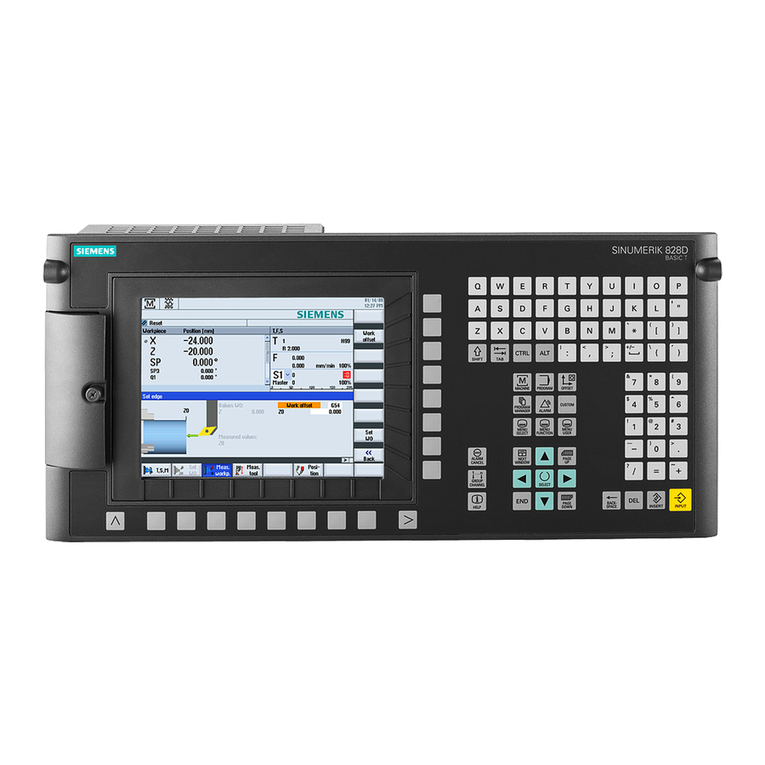
Siemens SINUMERIK 828D Turning Commissioning manual
