Balcrank Director Jr. 3110-031 Instruction Manual

!CAUTION
It is strongly recommended that shielded
wiring be used for ALL impulse meter
connections. The use of unshielded
wiring could results in erroneous dispense
volumes. The Director batch register
and the totaling register will read the
correct amounts requested, but the
actual dispense volume will be less. This
condition is a result of the unshielded
wiring picking up stray signals from
adjoining electrical wires and/or electrical
equipment. If unshielded wiring is used,
the condition described above will not
be covered under Balcrank’s Product
Warranty.
Thoroughly read and understand this manual before
installing, operating or servicing this equipment.
OPERATION, INSTALLATION,
MAINTENANCE AND REPAIR GUIDE
SERVICE BULLETIN SB3101
Rev. B 6/16
®
Director Jr.
Model #3110-031
24V DC Output

GENERAL SAFETY REQUIREMENTS
NOTE: THOROUGHLY READ AND UNDERSTAND THIS MANUAL BEFORE INSTALLING,
OPERATING, OR SERVICING THIS EQUIPMENT.
WARNING
!
DANGER:Notforusewithuids
thathaveaashpointbelow100°F
(38°C).Examples:gasoline,alcohol.
Sparkingcouldresultinanexplosionwhich
could result in death.
Check equipment regularly and
repair or replace worn and
damaged parts.
Never alter or modify any part of this unit,
doing so may cause damage to the unit and/or
personal injury.
Alwaysreadandfollowtheuidmanufacturer’s
recommendations regarding the use of proper
use, handling, and disposal.
Release pressures built up in the system
before any service or repair is begun on a
pressurized component on the system (e.g.
lters).Seethepressurereliefprocedure
below.
IMPORTANT
!
Pressure Relief Procedure:
Follow this procedure whenever you shut off
the pump, when checking or servicing any part
of the system and when installing, cleaning or
changing any part of the system.
1) Disconnecttheairtothepump.
2) Pointdispensingvalveawayfrom
yourself and others.
3) Opendispensingvalveuntil
pressure is relieved.
WARNING
!
WARNING
!
High Voltage may be present
when servicing this equipment.
This equipment should only be serviced by
authorized persons. Remove power from the
console before attempting to replace the
fuse.
Apressurereliefvalveattheuidsupplypoint
is mandatory for protection of the system and
personnel, and to maintain the warranty in
effect.ReliefKit3120-085(1/2”NPT)or3120-
086 (3/4” NPT) will protect the system from
possible overpressure damage. Excess uid
pressure above 850 psi (56 bar) is relieved.
Reliefoverowisdirectedbackintothesupply
container to reduce the risk of equipment
damage or serious bodily injury.
WARNING
!
1

2
TABLE OF CONTENTS
General Safety Information..............................................................................................................................1
Introduction.......................................................................................................................................................3
General Description............................................................................................................................................3
SystemSpecications ........................................................................................................................................3
ConsoleFeatures ...............................................................................................................................................3
Product Specications.....................................................................................................................................4
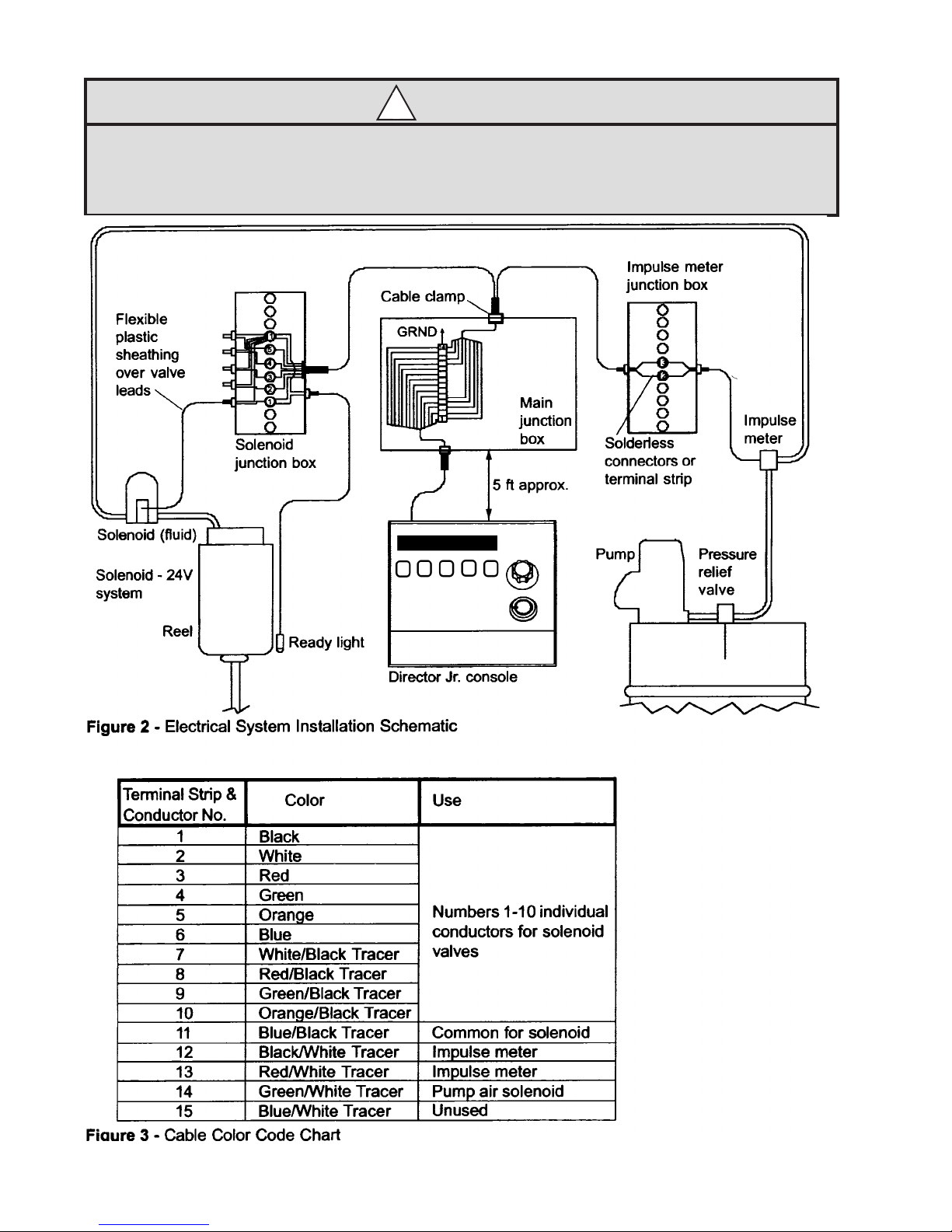
OperationalSchematic .......................................................................................................................................4
InterconnectionBox............................................................................................................................................5
Impulse Meter.....................................................................................................................................................5
Installation.........................................................................................................................................................5
General...............................................................................................................................................................5
Plumbing.............................................................................................................................................................5
Electrical.............................................................................................................................................................6
Wiring Diagram...................................................................................................................................................7
Console Setup ..................................................................................................................................................8
PulseCalibrationFactor .....................................................................................................................................9
Post Installation Check..................................................................................................................................10
OperationalCheck............................................................................................................................................10
Operation Instructions...................................................................................................................................10
NormalOperation .............................................................................................................................................10
TotalizerOperation ...........................................................................................................................................11
KeylockOperation ...........................................................................................................................................11
ReadyLightOperation......................................................................................................................................11
StationRotarySwitchOperation ......................................................................................................................11
Example............................................................................................................................................................11
Emergency Stop...............................................................................................................................................11
Reset ................................................................................................................................................................12
Service and Maintenance...............................................................................................................................12
General Policy ..................................................................................................................................................12
Periodic Inspection ...........................................................................................................................................12
Troubleshooting................................................................................................................................................12
Troubleshooting Chart ......................................................................................................................................13
Factory Service...............................................................................................................................................15
Repair...............................................................................................................................................................15
Parts List...........................................................................................................................................................15
Associated Components...................................................................................................................................15
Warranty Statement........................................................................................................................................17

INTRODUCTION
General Description
Controlleddispensingofmotoroil,ATF,gearoil,andantifreezeisavailablewiththeelectricalDIRECTORJR.
Theunitallowstheselectionofoneofuptoten(10)stations.OneDirectorJr.isrequiredforeachuidtype
dispensed. The console size is very small allowing for easy placement of as many units as may be required
forthenumberofuidstobedispensed.Eachunitiscompletelyself-contained.Theunitsofmeasurecanbe
set to quarts, pints, liters, or gallons. The voltage controlling the solenoid valves and the impulse meter is 24
VDC.
System Specications
Power Required.......................................................................................................................... 110 VAC, 60 Hz
Control Capacity............................................................................................................... 1 Product, 10 Stations
OperatingTemperature................................................................................................. 0°-140°F(-17°-60°C)
MaximumAmountDispensed......................................................................................99,999.9 Units of Volume
Impulse Meter Rating ............................................................................................................................... 30VDC
Resolution............................................................................................................................... 0.1 Unit of Volume
ControlOutputRating.............................................................................................................................. 24 VDC
Dimensions.....................................................................................................................5.7”Hx6.7”Wx5.7”D
MaximumFlowRate(ImpulseMeter)........................................................................................................8 GPM
Cable Length ...............................................................................................................................................6 feet
3

PRODUCT SPECIFICATION
Figure 1 showsasimplied,pictorialschematicofoneproductcontrolledto5stationsandreferencedexten-
sionofasixthstationaddition.
Typically, the following items are necessary:
1. Director Jr. (3110-031)-TheDirectorJr.allowscentralizedcontrolandmonitoringofindividualdeliveries
as well as a running total.
2. Isolation Air Valve (3230-004) - This valve will isolate the pump, air regulator, and air solenoid valve for
any servicing requirements, etc.
3. Air Regulator-Toregulateairpressuretothepump,sonottoexceed80psiand/orlimitpumpoutput
pressureto850psi(59bar)ifnormalairsupplywouldmakeithigherthanrecommended.
4. Air Solenoid Valve (3120-033) - This valve opens and closes air line to start the pump when activated by
theDirectorJr.(Balcrankrecommendsthisfeaturetohelppreventaccidentalspills.)
5. Pumps-1.3:1,3:1,5:1,and10:1ratioscanprovideandmaintainsufcientlinepressuresanduid
volumesformostsystems(systemplumbinglengthwilldictatepumpratiorequired).
6. Impulse Meter (3120-114) -Electricimpulsemetermeasurestheamountofuidthatisbeingdispensed.
System can be set to measure in quarts, liters, pints, or gallons.
7. Relief Kit (MANDATORY IN EACH SYSTEM) - 3120-085 for 1/2” NPT or 3120-086 for 3/4” NPT systems.
TheReliefKitlimitsuidpressurebuildupinlinesduetothermalexpansion,byrelievinguidpressure
over850psi(59bar).
8. Gate Valve-Isolatesthepumpanduidmeterfromuidow-backwhenservicing,etc.
9. Fluid Shut-off Valve (3230-002) - Isolates solenoid valve and dispensing station for servicing, etc.
10. Fluid Line Y-Strainer (3120-010 for 3/4” or 3120-040 for 1”)- Protects system against foreign
contaminants.
11. Fluid Solenoid Valve (3120-032) -
Thisvalveopensuidlinetodispens-
ing station when activated by the
DirectorJr.
12. Ready Light (3120-031) - Alerts the
operatorwhentheuidathisstation
has been enabled for dispensing.
Figure 1
Pictorial of a typical
DirectorJr.installation
4

Interconnection Box
ThereisnointerconnectionboxorjunctionboxprovidedwiththeDirectorJr.becausealloftheelectronicsare
containedintheconsole.Amultiwirecableisprovidedtoconnectinanyconvenientwiringbox.
Impulse Meter
Animpulsemeterisusedinthesystemtomeasuretheamountofuiddispensed.Thismeterisactuallya
simpleowmeterthatisinstalledintheuidline.Insidetheimpulsemeterisarotatingcamthatactuatesa
small microswitch that sends electrical impulses to the console. This meter can measure in quarts, pints, liters
or gallons.
INSTALLATION
General
TodeterminetheinstallationrequirementsforaDirectorJr.system(s),certainfactorsneedtobeestablished.
Ingeneral,thesefactorswilldeterminehowmuchmaterialsuchascablewire,uidlines,pumps,andetc.will
be needed. Answers to these questions below will help determine your material requirements.
1.Determinehowmanyuidtypesaretobedispensed.ThiswilldeterminehowmanyDirectorJr.systems
will be needed.
2. The number of reels or oil bars and solenoid valves needed will be determined by the number of stations
to be serviced.
3. Decidewheretolocatetheconsole(s),thereels,andoilbars,andtheuidsupplytanks.Oncethese
locationsareestablished,thelengthsofwire,cable,anduidlinescanbedetermined.
A pressure relief valve at the uid supply point is mandatory for protectionofthesystemand
personnel,andtomaintainthewarrantyineffect.ReliefKit3120-085(1/2”NPT)or3120-086(3/4”
NPT)willprotectthesystemfrompossibleoverpressuredamage.Excessuidpressureabove
850psi(56bar)isrelieved.Reliefoverowisdirectedbackintothesupplycontainertoreduce
the risk of equipment damage or serious bodily injury.
WARNING
!
Plumbing
TheDirectorJr.systemisacustomassemblytailoredtospecicneedsdependingontherelativepositionof
equipment, the number of products controlled and the number of stations for each product. To control a prod-
uct which will be monitored, an electric impulse meter will be installed in the main hydraulic line coming from
thepumporsourceofuidsupply,(Figure1,Item6).Themeterhas1/2”femalepipethreadsatbothinlet
and outlet. It is recommended that the meter be installed on a rigid line which will give it support. It is recom-
mendedthataexiblehosebeattachedbetweenthepumpandthemeter.Thiswillallowforslightmovement
orexingoftheinletline.
To make sure the system is as tamper proof and inconspicuous as possible, the impulse meter can be
installedatanypointinthehydrauliclinebetweentheuidsourceandtherstbranchofthesystem.Inthis
caseashortlengthofhoseatoneendissuggestedtosimplifythepipinghook-up.Acarefulstudyoftheoor
plan of the building where the system is to be installed should be made to determine the best location for this
meter, considering ease of installation and length of wiring to the console.
5

Theelectricuidsolenoidvalve(3120-032)isinstalledinthehydrauliclineasneartothepointofdispensing
aspossible(Figure1,Item11).Onevalvemustbeinstalledinthelineofeachoutlettobecontrolled.Itissug-
gestedthatamanualby-passvalvebeinstalledaroundthesolenoidvalveasshowninthediagram(Figure
1,Item9).Thisallowsthesolenoidvalvetobeby-passedincaseofelectricpowerlinefailure.Theby-pass
valve should allow for locking in either the open or closed position by means of a padlock or sealing wire to
avoid tampering.
ELECTRICAL
RefertoFigures2and3forelectricalinstallation.
InstallationshouldbemadeinaccordancewiththeNationalElectricalCode(NFPA70)andtheFlammable
andCombustibleLiquidsCode(NFPA30).
PowerinputtotheDirectorJr.is110VAC.Allcontrolcircuitsare24VDCwhicharenotnormallyrestrictedby
electrical codes, however, local codes should be checked for applicability, and all electrical installations should
comply with codes.
Placetheconsole(s)whereitwillnormallybeused.Allelectricalconnectionsaremadethroughthemulti-wire
cablesuppliedwiththeunit.Somekindofpullboxshouldbemountedwithin5feetoftheconsole.Asuitable
placemightbebehindadeskorintheceilingwheretheexistingelectricalsystemislikelylocated.Connect
thesuppliedcabletoascrewtypeterminalstripwith14terminalsthatismountedinsidetheboxasindicated
inFigure2.
No.18AWGwireisrecommendedforallrunslessthan400feet.Forrunsfrom400to625feet,usewireno.
16 AWG or larger. Normally the 24 VDC wiring can be run around the overhead structure of the building with-
out using conduit. This wire should be clamped or secured to the structure in such a way that it is not subject
toanymechanicalstress.Useastrainrelievingclampanytimeacableentersajunctionbox.Thecables
fromalltheconsolesinthesystemcanberuntoonejunctionboxwithconduitrunningtothe110VACcircuit
breakers and then using multi-wire cable for the control circuit runs.
Anotherjunctionboxshouldbeinstalledwithinafewfeetoftheimpulsemeter(lessthan10feet).Acontrol
cablecanthenbeusedtorunbetweenthisboxandtheconsolejunctionbox.Solderlessconnections(wire
nuts)canbeusedfortheconnectionsinthisbox.
Anotherjunctionboxorgroupofboxesshouldbemountednearthesolenoidvalves.Inthecaseofareel
bank,onejunctionboxmaysufceforseveralvalves.Intheeventthatanumberofreelbanksoroilbarsor
otherdispensingpointsareused,itmaybenecessarytolocateseparatejunctionsboxesateachdispensing
location. The two wires from each electrical solenoid valve should be run inside of plastic or metal sheathing
formechanicalprotection.Intheeventthatthejunctionboxislocatedatadistancefromthevalvegreater
than the length of the valve wires, it may be necessary to splice two ends of the wires together, soldering
them and then covering the connection with heat shrinking tubing.
Anoptionalextratothesystemisa“Ready”light(3120-031).Thislightisinstalledwithinsightofthedispens-
ing mechanic. It may be attached to the side of the reel bank, oil bar, or an adjacent wall. The wires of the
“Ready”lightareruntothesolenoidvalvejunctionboxandarewiredinparallelwiththevalve.
6

Before attempting to operate the system a careful check should be made of all wiring to assure
that all connections are secure and that no frayed leads cause an unwanted connection between
terminals or leads.
CAUTION
!
7

8
SETUP INFORMATION
General
DirectorJR.3110-031,VDCcomespreprogrammedwithpulsesettingsfromthefactory(seeTable1below).
Units shipped from the factory come pre-set for quarts.
When the system is powered on, the display will indicate:
-thecurrentsystemsettingswithadelayof2seconds(seeimage2below)
- the total ammount dispensed with a delay of 2 seconds
-normaloperationdisplay(seeimage1below)
FirstDigit Unit of Measure Pulses Per Unit
(after6/2016)
Pulses Per Unit
(before6/2016)
0. Quarts 310 155
G Gallons 1242 621
P Pints 156 78
L Liters 328 164
Image 2 - Current System Settings; Units and Pulses Per Unit
Image 1 - Normal operation display
TherstDigitindicatesthecurrentunitsetting(seetablebelow),andthelast4digitsindicatethe
pulsesperunit.Fortheimageabovetheunitissettoquartsand310pulses.
Table 1: Units and Factory pre-set pulses

9
CONSOLE SETUP INFORMATION (CONTINUED)
Entering the Setup Menu:
- StartwiththeunitpoweredOFF
- Whilepressingthe“Zero”and“Uparrow”buttons,poweronunitbyturningkeyto“ON”position.
SETUP DISPLAY
Pulse Calibration Factor:
- Can be set to 1 through 5, or negative 1 through 5, allowing you to adjust pulses per unit up or down 5
pulses.
•Use the “Up arrow” key to scroll between Quarts, Gallons, Pints, and Liters.
•Press the “SET” button to enter edit mode (The Pulse Calibration Factor will begin flashing)
•Use the “Up arrow” key to change the numerical values from 0 to 5, -1 to -5
•Press the “SET” button to exit edit mode
•When finished press the “TOTAL” button to save changes.
•Wait till the display looks like -->
•Power unit off with key
Units Pulse
Calibration
Factor
# Pulses
per unit
•Example
•Setting the Pulse Calibration Factor to “-2” would look like:
•When powering the unit on the display will show:
•Unit set for Quarts and 153 pulses per unit

POST INSTALLATION CHECK
Ifmanualby-passvalveshavebeeninstalledatthesolenoidvalves(Figure1,Item9),theyshouldbeopened
to allow checking the system for leakage before the electrical check out. The pumps should be set to operate
atnormalpressure(500psimaximum),andoildrawnfromeachdispensingpoint.Whenitiscertainthatall
air and foreign materials have been purged from all lines, the piping system should be checked for leaks. The
by-pass valves should be closed before proceeding with the electrical check out.
Operational Check
1. Double check all electrical connections for correctness and possible shorts and opens.
2. Turn on the circuit breaker for the console to be checked (it is suggested that only one system be checked
at a time.
3. FollowtheNormalOperationprocedurebelow,beingsuretoenteralargeamountforthistrialrun.
4. Rotate the Station Selector switch to each position. Stop at each position and make sure the solenoid .......
valveandtheremote“Ready”lightforthestationselectedison.Checktomakesurenostationisenabled....
other than the one selected. Also make sure the air pump is activated for the product associated with .......the
unitbeingcheckedout.Aseachstationisenabledandthelinespressurized,checkforleaks.NOTE:Leakage
not only causes a mess and a loss of product but it will also cause erroneous control of the ......amount of the
product delivered.
5. Aseachstationischeckedout,drawsomeuidfromeachlinetomakesurethatthelinesarefreeofair...
pockets.Alsomakesureitisthecorrectuid.
6. Nowthatthelinesareclearofair,dialinanappropriateamountofuidandchecktheaccuracyof delivery
ofeachtypeofuid.
It is suggested that when the check out is complete, that the consoles and their associated circuit breakers be
labeledbyuidtype.
OPERATION INSTRUCTIONS
Itisstronglyrecommendedthatthissystemnotbeconsideredfullyoperationaluntilthe“POST
INSTALLATIONCHECK”hasbeencompleted.Oncethecircuitbreakerscontrollingthepowerto
the system are turned on, all operations are controlled from the console.
CAUTION
!
Normal Operation
1. TurnpowerkeylockswitchtoON.
2. Set Station selector dial to desired setting.
3. Push“SET”;“SETACTIVE”lightshouldcomeon.
4. Push“SELECT”;thefarrightdigitwillash.Adjustthedigitvalueusingtheuparrow.Push“SELECT”to...
movetothenextdigit.Repeatthesestepsforallrequireddigits.
5. Whencompleted,push“SET”.“READY”lightshouldcomeonandstayonforthedelivery.
6. Dispenseuid.
7. Iftheentireamountisnotdispensed,press“ZERO”tozerothecount.
10

Totalizer Operation
The totalizer will accumulate and display the pulses received on the count input terminals. The Totalizer is
factory preprogrammed with a decimal value of 0.1, but it displays only the whole number accumulations that
arealsoindicatedonthedispensecounter(e.g.120.3onthedispensecounter=120ontheTotalizer).Count
capacityis8digits.Toreadthetotal,pressandhold“TOTAL”.
Key lock Operation
TheDirectorJr.isequippedwithasecuritykeylocktoenablethesystem.Thekeymustbeinsertedand
turnedtotheONposition(12o’clockposition)toenabledispensing.TheDirectorJr.shouldhavepower
applied prior to turning on the key lock switch to assure that the controller is initialized.
Ready Light Operation
TheDirectorJr.isequippedwitharedlighttoindicatewhenthedispensingsystemisarmedandreadyfor
dispensing. If the light is not illuminated then the system is not operational.
Station Rotary Switch Operation
The Station Rotary Switch controls the station which is authorized to dispense the preset amount. Stations
are numbered 1 through 10.
Example
Assume that the operator of station 3 wants to add 4 quarts of oil to a car. He contacts his supervisor who will
enabletheDirectorJr.tometertherequiredoil.Thesupervisorwouldperformthefollowingsteps:
1. AssurethattheDirectorJr.haspower.
2. PushinandturnthekeylockswitchtotheONposition.
3. Turn the station rotary switch to the number 3 position.
4. Push“SET”.
5. Push“SELECT”buttonuntiltheseconddigitisashing.Usetheadjustthedigitto4usingtheuparrow.
6. Push“SET”andthereadylightwillilluminateandtheoperatorinstation3isenabled.
7. Theoperatorinstation3dispensestheuid.Thecounterdecreasesintenthsandthetotalizerincreasesin
whole numbers.
8. When the counter reaches 0.0, then the ready light turns off and dispensing is complete.
9. Turn off the key lock switch to prevent further unauthorized dispensing.
Emergency Stop
Intheeventthattheuidowmustbestoppedimmediatelyduetoleakageorotheremergencysituation,
TURN OFF THE KEY LOCK SWITCH.Thisactionshutsoffthesolenoidvalvewhichstopstheowofuid.
Simply unplugging the Director Jr. will not provide emergency shutoff.
Reset
Iftheamountofdeliveryneedstobechangedorcorrectedafter“SET”hasbeenpressedorafterowofuid
hasalreadystarted,presszeroandstartover.Ifsomeuidhasalreadybeendispensed,thatamountshould
be subtracted from the new setting.
11

SERVICE AND MAINTENANCE
General
NoattemptshouldbemadetorepairtheDirectorJr.consoleunit.Acertainamountofinformationabout
servicing and troubleshooting is provided in this manual but if questions arise, contact your Balcrank Service
Representative or the Balcrank factory Service Department. Customer repairs that are beyond the scope of
this manual become the sole responsibility of the customer.
Periodic Inspection
InspectionoftheDirectorJr.systemshouldbeconductedatregularintervalsbyqualiedpersonnel.The
frequency of these inspections should be based on operating rate and environmental conditions. While the
systemisbuiltforexcellentreliability,thecompletesystem,includingtheelectronic,electro-mechanicaland
mechanical parts need periodic inspection for optimum life. Here is a suggested list of areas to check:
1. Inspect the wiring, cable, and electrical connections.
2. Make sure all components of the system are still secured properly on their mounting surfaces.
3. Check all screws, nuts and bolts to make sure they have not worked loose.
4. Carefully clean the console with a lint free cloth dampened with a mild detergent. Do not pour or spray ......
cleanerdirectlyontheconsole.DONOTLETLIQUIDENTERTHECONSOLE.
5. Check all switches and lamps for proper operation.
6. RefertoPOSTINSTALLATIONCHECKtoverifyforproperoperation.
Make sure that the power is turned off before removing any components or disconnecting any
connections or wiring.
WARNING
!
Troubleshooting
In order to properly troubleshoot the system and perform replacement or repair of parts, it is necessary that
thetechnicianperformingtheworkbethoroughlyfamiliarwiththeequipment.Attemptedrepairbyunqualied
personnel could void the warranty. It is suggested that this manual be studied thoroughly before any trouble-
shooting is attempted.
Itissuggestedthatwheneverthereisaproblemwiththesystemthatavisualinspectionrstbemadeofthe
overall condition of the equipment. Here is a list of things to look for:
1. Inspect for corrosion of components or wiring.
2. Check for frayed or broken insulation of wires and cables, and make sure their connections are secure.
3. Make sure all components are mounted securely.
4. Check front panel components to make sure none are cracked or broken.
5. Alldecienciesshouldbecorrectedbeforeproceedingwithtroubleshooting.
12

TROUBLESHOOTING CHART
In order to properly troubleshoot the system and perform proper replacement or repair of parts, it is neces-
sary that the technician performing the work be thoroughly familiar with the equipment. Attempted repair by
unqualiedpersonnelcouldvoidthewarranty.Itissuggestedthatthismanualbestudiedthoroughlybefore
any troubleshooting is attempted.
Itissuggestedthatwheneverthereisaproblemwiththesystemthatavisualinspectionrstbemadeofthe
overall condition of the equipment. Here is a list of things to look for:
WARNING
!
Make sure that the power is turned off before removing any components or disconnecting any
connections or wiring.
Symptom Cause Solution
1. No power at console. Blown fuse. Replace fuse.
Circuit breaker tripped. Reset breaker at main panel.
Unit not plugged in. Plug unit in.
Damaged line cord. Replace line cord.
Cable not connected or Plug in cable connector.
properly seated.
Key lock switch off. Turn on key lock.
2. System power is on Unit is defective Return the unit for repair.
but the keypad will not
accept any inputs Cable is not connected or Plug in cable connector.
properly seated.
3. Display not illuminate, Counter is defective. Return the unit for repair.
or digit elements are
incomplete.
4.Consolecontrolsthe Controlwirestothesolenoid Rewireasspecied.
wronguid. valvesareimproperlyconnected.
13

Symptom Cause Solution
5. System has power and Pump is not operating. Check the air supply to the pump
goes into ready mode, and the pump air solenoid valve.
butnouidcanbe
dispensed. Outofuid. Checktheuidlevelinthestorage
container.
Control solenoid valve not Check valve for energized position.
operating.
Outletofpumpisblocked. Checkimpulsemeterandcontrol
solenoid valve for blockage.
Defective station selector Return the unit for repair.
switch.
System not properly wired. Recheck electrical connections and
rewireasspecied.
Cable not connected or properly Plug in cable connector.
seated.
6.Fluiddoesnotcutoff Impulsemetersetupforthe Checktheimpulsemeterforthe
at the correct preset wrong units. correct volume per pulse.
Impulse meter cam plate not Check the position of the pulse
actuating pulse switch at each switch in relation to the cam lobes.
cam lobe. The pulse switch is Also check for broken cam lobe.
out of position. Adjust or replace as required per
meter instructions.
Defective unit. Return the unit for repair.
7.Remote“Ready”light Remote“Ready”lightbulb Replacebulb.
will not come on, but burned out.
theconsole“Ready”
lightdoes. Remote“Ready”lightimproperly Correctorreplaceremotewiring.
wired or faulty wiring.
14

FACTORY SERVICE
Repair
NoattempttorepairtheDirectorJr.shouldbemadebeyondthescopeofthismanual.Themodulardesign
of the unit, made possible by the use of integrated circuits, makes it necessary to have access to special test
equipment if serious damage to the system is to be avoided. The unit should be returned to a Balcrank autho-
rized Service Center for repair or adjustment.
Parts List
Key ..........................................................................................................................................................832011
Fuse(1amp,250V).................................................................................................................................833445
Cableonly(for3110-031) ........................................................................................................................832013
Associated Components
PressureReliefKit(1/2”NPT)............................................................................................................. 3120-085
PressureReliefKit(3/4”NPT)............................................................................................................. 3120-086
IsolationAirValve(1/2”NPT) .............................................................................................................. 3230-004
Air Solenoid Valve ............................................................................................................................... 3120-033
ImpulseMeter(universal;quarts,liters,pints,gallons) ........................................................................3120-114
FluidShut-offValve(1/2”NPT)............................................................................................................ 3230-002
FluidLineY-Strainer(3/4”NPT) .......................................................................................................... 3120-010
FluidLineY-Strainer(1”NPT) ............................................................................................................. 3120-040
FluidSolenoidValve ............................................................................................................................ 3120-032
Ready Light ......................................................................................................................................... 3120-031
Revision Log:
Rev. A - Release
RevB-June1016-Updatedpulsesformeterswith4magnets/doublepulses.
15

16
NOTES:

Balcrank®Corporation
Weaverville, NC 28787
800-747-5300
800-763-0840Fax
www.balcrank.com
SERVICE BULLETIN SB3101
Rev. A 2/15
For Warranty Information Visit:
www.balcrank.com
Table of contents
Other Balcrank Controllers manuals
Popular Controllers manuals by other brands

CitrinSolar
CitrinSolar CS 2.5 Mounting and operating instructions

SmartPID
SmartPID M5 Mini quick start guide

Reclaim
Reclaim v1 Product update

Curtiss-Wright
Curtiss-Wright EXLAR Tritex II AC Installation and service manual

Johnson Controls
Johnson Controls M91 GDA-1N Series installation instructions

Shimaden
Shimaden MR13 Series instruction manual