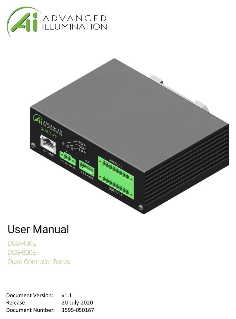
Advanced Illumination Quad Controller Series User manual

Document Version: v1.0
Release: 5-Aug-2019
Document Number: 1595-050167
User Manual
DCS-400E
DCS-800E
Quad Controller Series
DCS-400E
DCS-800E
Quad Controller Series

Page 2 of 22
Version History
Version
#
Implemented
By
Revision
Date
Approval
Date
Reason
0.1
Initial Design Definition draft
0.2
JRS
5/20/2019
Updated cad images and wiring
diagrams
0.3
RRR
8/2/2019
SW Command List Added
1.0
JRS
8/05/19
8/5/2019
Updated front panel images, readied
document for release

Page 3 of 22
Contents
DCS-400E DCS-800E Quad Controller Series ............................................................................................ 1
Version History ................................................................................................................................................ 2
Hardware Overview.......................................................................................................................................... 4
Installation Model............................................................................................................................................ 5
General Specifications .................................................................................................................................... 6
Front Panel Illustrations.................................................................................................................................. 7
Front Panel Descriptions................................................................................................................................. 8
Important Information.............................................................................................................................. 9
Output Connector......................................................................................................................................... 9
Quick-Start..................................................................................................................................................... 10
General Connection Diagram .................................................................................................................... 10
Modes of Operation ................................................................................................................................... 11
Continuous ............................................................................................................................................. 11
Pulsed ..................................................................................................................................................... 11
Sequence................................................................................................................................................ 11
Trigger Input & Outputs ............................................................................................................................. 12
Software Setup .............................................................................................................................................. 13
Default Ethernet Settings .......................................................................................................................... 13
User Interface (GUI) ................................................................................................................................... 14
Software Usage ............................................................................................................................................. 15
Overview..................................................................................................................................................... 15
Modes......................................................................................................................................................... 16
Standard Mode....................................................................................................................................... 16
Sequenced Mode.................................................................................................................................... 17
Network Configuration............................................................................................................................... 18
Static IP configuration........................................................................................................................... 18
Resetting to DHCP ................................................................................................................................. 18
Software Command and Control Interface................................................................................................... 19
Command Structure .................................................................................................................................. 19
Command Table......................................................................................................................................... 20
Warranty Information .................................................................................................................................... 22
Technical Support and Product Information................................................................................................ 22

Page 4 of 22
Hardware Overview
The DCS400 and DCS800 Quad Lighting Controller is a multi-channel controller for
Advanced Illumination LED illuminators. With multi-channel control, this controller is
ideal for applications such as photometric stereo, high-resolution color and bright-field
/ dark-field combination lighting.
This controller family is not limited to computational imaging and can be used as a
general-purpose controller for a wide range of applications in both continuous and
strobe modes of operation.
DCS-400E, Quad Controller
•Single Output, 4 Channels
•x2 digital trigger input
•X2 trigger outputs
DCS-800E, Quad Controller x2
• Dual Output, 8 Channel
•x2 digital trigger inputs
•X2 trigger outputs
Figure 1
Figure 2

Page 5 of 22
Installation Model
Figure 3

Page 6 of 22
General Specifications
Specification
DCS-400E (single output)
DCS-800E (dual output)
Power Requirements
24VDC Nominal, 4.5A
Vmin = 22VDC
Vmax = 48VDC
Output Power
Up to 100W total
5A Pulsed (24V input)
*10A pulsed *(48V input)
1A continuous per channel
Channel Control
4 Independent Channels,
1 Output
8Independent Channels,
2 Outputs
Modes
Continuous, Pulsed, or Gated Continuous
External Trigger
Input/Output
5V, TTL Compatible
Overvoltage protected, safe up to 30VDC
Pulse Width Range
30usec to 1 hour
Trigger-to-Pulse Latency
30 usec delay
2us rise/fall
Duty Cycle / Frequency
15% duty cycle limit in overdrive/pulsed
mode*
*Longer duty cycles possible at
“continuous” current ratings
Operating Temperature
Range
0 °C to 60 °C
Communication / Software
10/100 Ethernet Standard TCP-IP, UDP
.NET library compatible with C#, F# and VB
Windows Software

Page 7 of 22
Front Panel Illustrations
Front Panel Illustration, DCS-400E
Front Panel Illustration, DCS-800E
Refer to the tables on the next page for connection info
Figure 4
Figure 5

Page 8 of 22
Front Panel Descriptions
Table 1 - Input Power, P1
Pin
Description
Note
1
24-48VDC
Reverse polarity protected
2
DC GND
Table 2 - Indicator LEDs
Color
Behavior
Function
LED 1
Green
On
Main Power Indicator
LED 2
Amber
Heartbeat /
Blink
Flashes once per second heartbeat while light is connected. Flashes
when commands are received.
LED 3
Red
Blink Code
Error code—Long / Medium / Short flashes indicate an error code
Table 3 – IO Connector, P2
Pin
Description
Note
1
TRIGGER-IN1
ACTIVE-HIGH — pull high to activate (Channels 1-4)
2
TRIGGER-IN2
ACTIVE-HIGH — pull high to activate
(Channels 1-4 for DCS-400E, Channels 5-8 for DCS-800E)
3
TRIGGER-OUT1
Frame Start—output signal, occurs at the beginning of each channel
pulse
4
TRIGGER-OUT2
Frame Stop—output signal, occurs at the end of each channel pulse
5
TRIGGER GND
Same as DC ground
6
TRIGGER GND
Same as DC ground

Page 9 of 22
Table 4 – Output Connector P3 & P4
Output 1 (P3)
Output 2 (P4)
Notes
Pin
Description
Pin
Description
1
SignaTechTM
GND
9
SignaTechTM
GND
Reserved
2
SignaTechTM
10
SignaTechTM
SignaTechTM Light Protection — NOT USER SERVICEABLE
3
CH3 & CH4 -
11
CH7 & CH8 -
LED Cathode (common)*
4
CH4 +
12
CH8 +
LED Anode
5
CH3 +
13
CH7 +
LED Anode
6
CH1 & CH2 -
14
CH5 & CH6 -
LED Cathode (common)*
7
CH2 +
15
CH6 +
LED Anode
8
CH1 +
16
CH5 +
LED Anode
Important Informaon
*LED Cathode pins, pin 1 and pin 9 are COMMON and may be tied together.
This controller requires SignaTech to operate correctly. SignaTech is included with lights purchased
from Advanced Illumination. It is not possible to drive a non-SignaTech protected light source without
explicit instruction from Advanced Illumination.
Output Connector
Plug: Phoenix Contact, 1827761
Strain Relief: Phoenix Contact, 1834408

Page 10 of 22
Quick-Start
General Connection Diagram
Figure 6 – General Wiring Example

Page 11 of 22
Modes of Operation
Connuous
Each channel is capable of up to 1A output in standard mode. Continuous mode
is not possible in sequence mode; in sequence mode, DC can be simulated by
using long pulse widths.
Note: Depending on the load and power dissipation, not all channels may
operate at 1A simultaneous. The controller must maintain a safe power
dissipation, so channel currents may be throttled.
Pulsed
Pulsed mode illumination is triggered by an external signal.
Pulse widths and delay are available from 10 to 4,290,000000 microseconds
and can be applied independently to any channel.
Sequence
Channels settings are organized into events. The event could be considered a
pre-set, or recipe, that stores the behavior when a trigger is received.
Programming multiple events allows the controller to sequence through pre-
determined recipes. Each external trigger edge will advance the sequence to the
next event.

Page 12 of 22
Trigger Input & Outputs
Simplified Input Diagram (P2 pins 1 & 2)
Outputs – Frame Start/Stop (P2 pins 3 & 4)
Frame-start (Pin 3) is an output trigger signal that occurs at the beginning of each
channel pulse. This signal can be used to trigger an external device, or camera.
For example: by using the frame-start signal, it is possible to synchronize a camera
exposure to capture each channel as they flash in a sequence. This is useful in
photometric stereo applications where the camera needs to be carefully synchronized
to capture multiple flashes
Frame Stop (pin 4) -- Similar to frame-start except the stop signal begins at the end of
each light pulse. This signal can be used to determine when the last channel pulse has
ended and is useful for controlling system timing more accurately.
Internal to
controller
Internal to
controller

Page 13 of 22
Software Setup
Default Ethernet Settings
The Controller uses standard Ethernet protocol (TCP-IP and UDP) to communicate. The DCS control user
interface can be used to communicate, or other software may be used to send data packets directly
from the host to the controller.
Table 5
Setting
Value
Typical Port Settings
UDP, port 7777
TCP, port 777
DHCP
Enabled by default
Default IP Address
192.168.0.5
*Controller will use default IP if DHCP fails upon power up, or
if an Ethernet cable is not connected
User Assigned IP Addresses
User can assign a new IP address by sending a command, or
entering a new IP address in the “manage devices” window of
the GUI.
If a user assigned IP address is used, the controller will not
begin using that IP address until the controller power is
toggled.
Figure 7 - Example PC settings
This controller uses DHCP to automatically acquire
an IP address. If directly to a PC Ethernet port, you
will need to set up the PC to use a static IP address
in the range of 192.168.0.x

Page 14 of 22
User Interface (GUI)
1.This dropdown box will list any discovered devices by IP address. Select the devices
you want to connect to here. The refresh button will re-scan for devices on the
network, and the connect button will connect to the highlighted IP address.
2. Editing channels exists in a section we call Events. Default startup is Event 1, but
additional events can be created to store pre-set configurations.
3. Save Event will store the event in memory, as well as run the event once pressed
4. Sequences can be used to chain different events together. Note, you should have at
least 1 default sequence set up even if only 1 event is running.
Figure 8
1
2
3
4

Page 15 of 22
Software Usage
Overview
The Ai DCS-400/800 software must connect to a device before it can be used. The Refresh button (see
Figure 95) refreshes the list of available DCS-400/800 devices on the local network. Either select a
device from the list or type an IP address (in dotted-quad, e.g. “XXX.XXX.XXX.XXX” format) and click
connect.
Figure 95: Software main window example

Page 16 of 22
Modes
Standard Mode
The standard mode allows using a DCS-400 or DCS-800 like a “normal” 4- or 8-channel controller.
Operation in Standard Mode starts by putting the controller in Standard mode and adding an Event (See
Figure).
Figure 10: Image of Standard mode and Event add
Adding an Event
Once an event is added, you can set configurations (current, channel mode, etc.) on each channel and
they will be immediately reflected on the controller. Note that the event itself is not auto-saved: if you
power down the controller the configuration will be lost unless you click “Save all Events”. The warning
shown in Figure 6 will inform you if you have unsaved edits.
Figure 61: Unsaved event warning
Other events you add must be loaded with the Load Event button to be applied to the device. Loading an
Event will set that Event active on the device, and it will be auto-loaded next time the device is powered
on. If no Event is loaded when the device is power cycled, it will load the first available saved Event.
Saving channel configurations as an Event allows you to easily recall the configurations later, much like
the Profiles in Advanced illumination’s DCS-100 and DCS-103 controllers.

Page 17 of 22
Sequenced Mode
Sequenced mode allows the controller to automatically cycle through a predefined series of Events with
a hardware trigger (currently only Trigger Input 1). This allows the controller to, for example, flash
alternate sides of a right light with only one a continual stream of trigger pulses and no further input
from the software/SDK.
Events
Creating an Event is the same as in Standard Mode, except for two points:
1. Event changes are not immediately updated on the device.
2. An Event cannot be loaded directly while in Sequenced Mode, only Sequences can.
Sequences
Figure 72: Sequence editing menu
A Sequence is, at its simplest, a list of Events. When a Sequence is loaded, a hardware trigger causes
the controller to start the first Event in the list, the next trigger starts the next event, and so on. When the
last Event in the Sequence is reached, it starts over from the first Event.
The sequence menu is shown above in Figure 7. Clicking “Add Sequence” adds a new sequence, which
appears inline below the other sequences in the list. On any Sequence, you can select an Event from the
dropdown in the Sequence and click “Add selected event” to add that event to the Sequence. You can
have multiple of the same Event in the Sequence, however you are limited to 10 Events per sequence.
Once you have a Sequence defined, click “Save sequences” to save all defined Sequences to the
controller. You can then make load a Sequence on the controller by clicking “Set as active” on a
sequence. The “Run sequence” button allows you to simulate a trigger pulse to ensure that sequence is
working as intended. Be aware that this button sends an HTTP POST message to the controller, so there
will be network delay between the click and the pulse.

Page 18 of 22
Network Configuration
Network Configurations are viewed by clicking the “Network Configuration” button on the main window
when connected to a device. Network Configurations opens in its own window, as shown in Figure 8
below.
Figure 83: Network Conguration example in DHCP Mode
Stac IP conguraon
A static IP address is set by entering an IP address, subnet mask, and Gateway address in the boxes
provided. Note that the window displays the current value of all settings, even if it’s using DHCP.
Settings are saved by clicking the “Save Settings” button. If settings are saved unchanged from the
values displayed from DHCP, then the device is assigned a static IP address configuration matching
those values.
Reseng to DHCP
Network configuration can be reset back to DHCP mode by clicking the red-text “Reset to DHCP” button,
which will replace the green DHCP message when the device is using a static address. The device
should then be power-cycled for it to use its new settings.

Page 19 of 22
Software Command and Control Interface
Command Structure
The DCS400/800 uses an SCPI-like interface where commands are a series of readable strings with
parameters separated by commas. The strings must be terminated by a semicolon (‘;’) for proper
operation.
Commands can be sent in an ASCII format by specifying the IP Address and correct port number for
either TCP/IP or UDP.
Commands with a parameter
Commands that require a parameter have it separated by a comma.
Example: “SET:PULSE:WIDTH:CHANNEL1, 100;”
Where “SET:PULSE:WIDTH:CHANNEL1,” is the command and “100” is the parameter.
Commands without a parameter
If the command has no parameter, the command simply ends with a semicolon.
Example: “*IDN?;”

Page 20 of 22
Commands are case sensitive, and must be entered exactly as shown
Command Table
Table 6
COMMAND
DESCRIPTION
RETURNS
SET:CURRENT:CHANNELc,nnnn;
Sets the current in
milliamps
c = 1 - 8 (channel
number)
nnnn= 0-8000 (strobe)
SET:PULSE:WIDTH:CHANNELc,nnnn;
Sets the pulsewidth in
usec
c = 1 - 8 (channel
number)
nnnn = 0 – 4290000000
(us)
INFO: Channel “c” pulse
width set to “nnnn” us
SET:PULSE:DELAY:CHANNELc,nnnn;
Sets the pulse delay in
usec
c = 1 - 8 (channel
number)
nnnn = 0– 4290000000
(us)
INFO: Channel “c” pulse
delay set to “n”
microseconds.
PULSE:CHANNELc;
Software triggers the
channel
c = 1-8
*IDN?;
Gets device information:
firmware, hardware,
etc..
Advanced illumination
“DCS-100: (fw version, hw
version)”
*CHANNEL:INFO?;
Gets device channel
information
SET:IP:ADDRESS,xxx;
Sets static IP address.
Xxx = IP address in
dotted-quad format
(XXX.XXX.XXX.XXX)
INFO: Set IP address to
XXX.XXX.XXX.XXX. Reboot for
it to take effect.
This manual suits for next models
2
Table of contents
Other Advanced Illumination Controllers manuals
