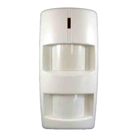
SECOLink BK4 User manual

BK1, BK2, BK3, BV3, BK4 and BT1 Wireless detectors
Intruder alarm system
BK1, BT1: ~3 years
BK3, BV3, BK4: ~2 years
BK2: ~1,5 years (with extra
load of 20 uA on terminal 3)
INSTALLATION
4 5 6
Installation manual
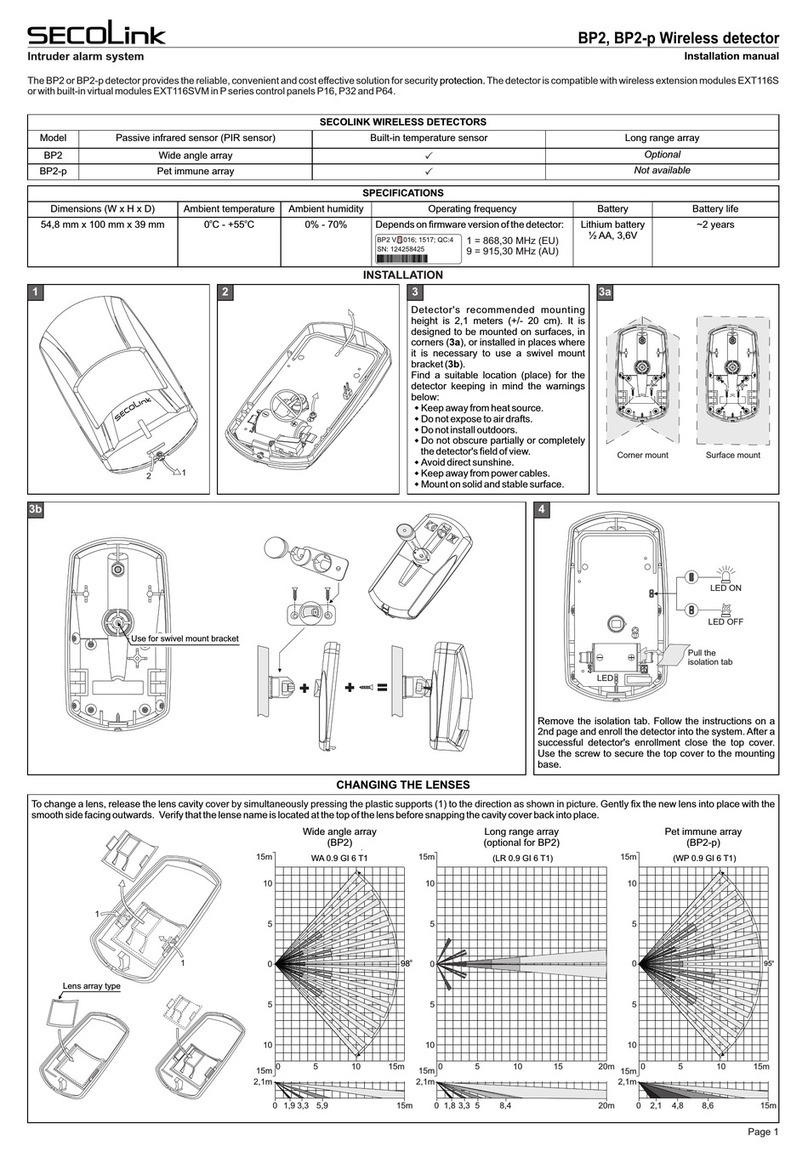
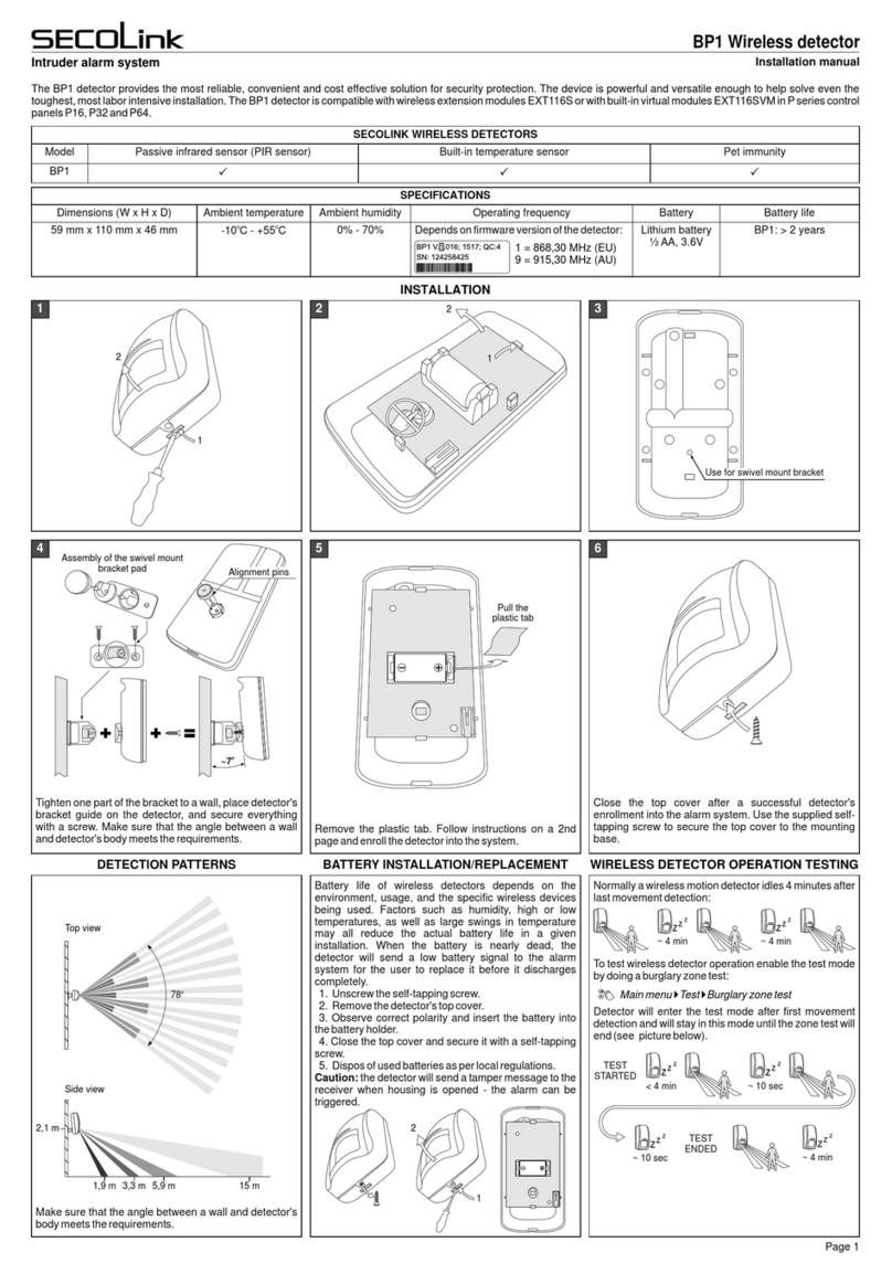
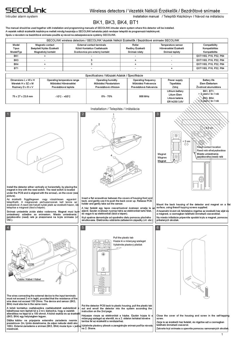
The Bx series detectors (BK1, BK2, BK3, BV3, BK and BT1) provide the mo convenient and cost effective solutions for security devices are powerful 4protection. Thesest reliable,
and versatile enough to help solve even the toughest, most labor intensive installations. All Bx series detectors are compatible with wireless extension modules EXT116S or with
built-in virtual modules EXT116SVM in P series control panels P16, P32 and P64.
1
2
3
4
2
> 0,5 cm
Magnet (BK1, BK4)
Reed switch
location
Magnet alignment
marks
Tamper
Wire entry hole
1
SECOLINK WIRELESS DETECTORS
SPECIFICATIONS
Model Built-in reed switch (used in
conjunction with a magnet)
Dimensions (W x H x D)
Input loops (zones) for
wired applications
Ambient humidity
Built-in temperature
sensor
Ambient temperature
Supports wired Roller
detectors
Battery
Supports wired
Vibration detectors
Battery life*
BK1
BK2
BT1
BK3
BV3
BK4
27 mm x 75 mm x 23,6 mm
o o
-10 C - +55 C
2
0% - 70%
3
3
3
Depends on firmware version of the detector:
Lithium battery
½ AA, 3,6V
Supports wired normally
closed circuit contact loops
Operating frequency
1 = 868,30 MHz (EU)
9 = 915,30 MHz (AU)
3
TamperTamper
Flat surface Non-flat surface
The detector includes a built-in tamper that can be
activated if the detector is mounted on a non-flat surface.
Remove the plastic tab. Follow the instructions on the
2nd page and enroll the detector into the alarm system.
After a successful detector's enrollment close the top
cover. Use the supplied self-tapping screw to secure the
top cover to the mounting base.
Recommended maximum gap separation for insta-
llations on non-ferromagnetic surfaces is 25 mm and for
ferromagnetic surfaces is 5 mm.
Pull the
plastic tab
Battery life of wireless detectors depends on the environment, usage, and the specific wireless devices being used.
Factors such as humidity, high or low temperatures, as well as large swings in temperature may all reduce the actual
battery life in a given installation. When the battery is nearly dead (low battery threshold voltage < 2,45V), the detector
will send a low battery signal to the alarm system for the user to replace it before it discharges completely.
1. Unscrew the self-tapping screw.
2. Remove the detector's top cover.
3. Observe correct polarity and insert the battery into the battery holder.
4. Close the top cover and secure it with a self-tapping screw.
5. Dispose of used batteries as per local regulations.
Caution: the detector will send a tamper message to the receiver when housing is opened - the alarm can be
triggered.
BATTERY INSTALLATION/REPLACEMENT
1
2
Caution: make sure that loop wires do not short any
components on circuit board.
up to 2 m
Ferromagnetic surfacesNon-ferromagnetic
surfaces
Approach/make: 10mm
Removal/break: 12mm
Approach/make: 28mm
Removal/break: 30mm
Approach/make: 34mm
Removal/break: 38mm
Approach/make: 50mm
Removal/break: 55mm
Approach/make: 28mm
Removal/break: 33mm
Approach/make: 5mm
Removal/break: 7mm
Page 1
Thin "breakout"
area for cable
Top cover
3
Detector
NC
C
Detector
NC
C
1
2
3
COM
BK2:
C - COM
1 - input 1
2 - input 2
3 - output (+3,6V)
BV3, BK3, BK4:
C - COM
1 - input 1
2 - input 2
3 - input 3
C NC
Magnetic contact /
Roller / Vibration
+3,6V
COM
To input
Cable
C NC
COM
To input
External detector,
powered from BK2
(current < 20uA)
* calculated battery life expecting that there will be 12 events and 12 restores

Intruder alarm system
ENROLLING
1
Ser v ic e m ode
System setup
Enable the wireless zone by changing Not used
loop type to any other loop type. If the system uses a
keypad produced before 2014, an installer is
obligated to change the loop type to NO/DEOL or
Vibration.
Advance to the next unlearned zone with keypad
keys [Ü] or [7].
1
Z01 D o o r
Name Door
3
System setup
Zones
Z01 D o o r
Loop ty p e NO/DEOL
3
Z01 D o or
WL det. l o o p ( zone) ID 2 01
4
Z01 D o o r
Address 0 6 _ 1
3
Enter the zone address in MA_Z format, where MA
is a module address in the system and Z is a zone
number in the module.
Note: for wireless zones MA_1 – MA_8 the system
will automatically assign NO/DEOL loop type and
for wireless zones MA_9 – MA_16 the Vibration
loop type. Don't change the loop type of a zone!
Module address:
EXT116S - address 06 (default) or given during
the registration process;
Virtual module EXT116S address depends on the
control panel's type:
P16 - address 12;
P32 - address 12 and 13;
P64 - address 12, 13, 14 and 15.
Enter wireless detector’s loop (zone) ID number
and press the [ENT] key to start enrolling. This field
may also be used for deleting the sensor from the
module.
Done
Wai tin g for
WL detector
Wireless detector successfully enrolled. No
additional transmissions are needed for
confirmation.
BK1
BK4
Use Supports Wireless detector loop (zone) ID number
Built-in reed switch
(used in conjunction
with a magnet)
200
255
Normally closed
circuit contact loop
wired to ...
Roller detector
loop wired to ...
Vibration detector
loop wired to ...
BK3
BK2**
BK4
210
211
111
... input 1
... input 1
220
221
121
... input 2
... input 2
230
231
131
... input 3
... input 3
212
112
222
122
232
132
213 223 233
215 225 235
217 227 237
219
...
118
119
229
...
128
129
239
...
138
139
Zone response (speed) time of 0,4 sec.
211 - last digit of identification code defines the
number of Roller pulses.
111 - last digit of identification code number x 10
defines the zone response (speed) time (example: 1 x
10 = 10 msec).
Temperature
sensor BT1
BK3
BK2**
BV3
BK4
... input 1 ... input 2 ... input 3
BV3
Delete the detector
in a particular zone
Delete all
detectors in a
specific wireless
module
All
All
201
254
** wireless detector loop (zone) ID number for input 3 is not used.
Installation manual
BK1, BK2, BK3, BV3, BK4 and BT1 Wireless detectors
Wireless detector loop (zone) enrolling ID numbers
When enrolment has started, immediately press the
detector's battery for a short period of time (~1 sec)
as shown in the picture. You will feel a light click after
pressing the battery. The tamper switch is now
activated and the detector will transmit a tamper
message.
Page 2
Please act according to your local rules and do not dispose of your unusable alarm system or its components with other household waste. This
product utilization in EU is covered by European Directive 2002/96/EC.
Kodinis Raktas UAB, manufacturer of SECOLINK Intruder Alarm System, offers a Warranty for a term of twenty-four months. It declares, that
product BK1 complies with essential EU directives and EU standards EN 50131-1, Grade 1, Environmental Class II;
EN 50131-2-6. For more information visit manufacturer’s website www.kodinis.lt or www.secolink.eu for a complete text of declaration.
SECOLINK Intruder Alarm System is designed and manufactured in Lithuania.
SYSTEM COMPLIANCE AND WARRANTY
Rev.30/11/16_KF
Other manuals for BK4
3
This manual suits for next models
5
Table of contents
Other SECOLink Security Sensor manuals
