SECOLink BS100 User manual

BS100
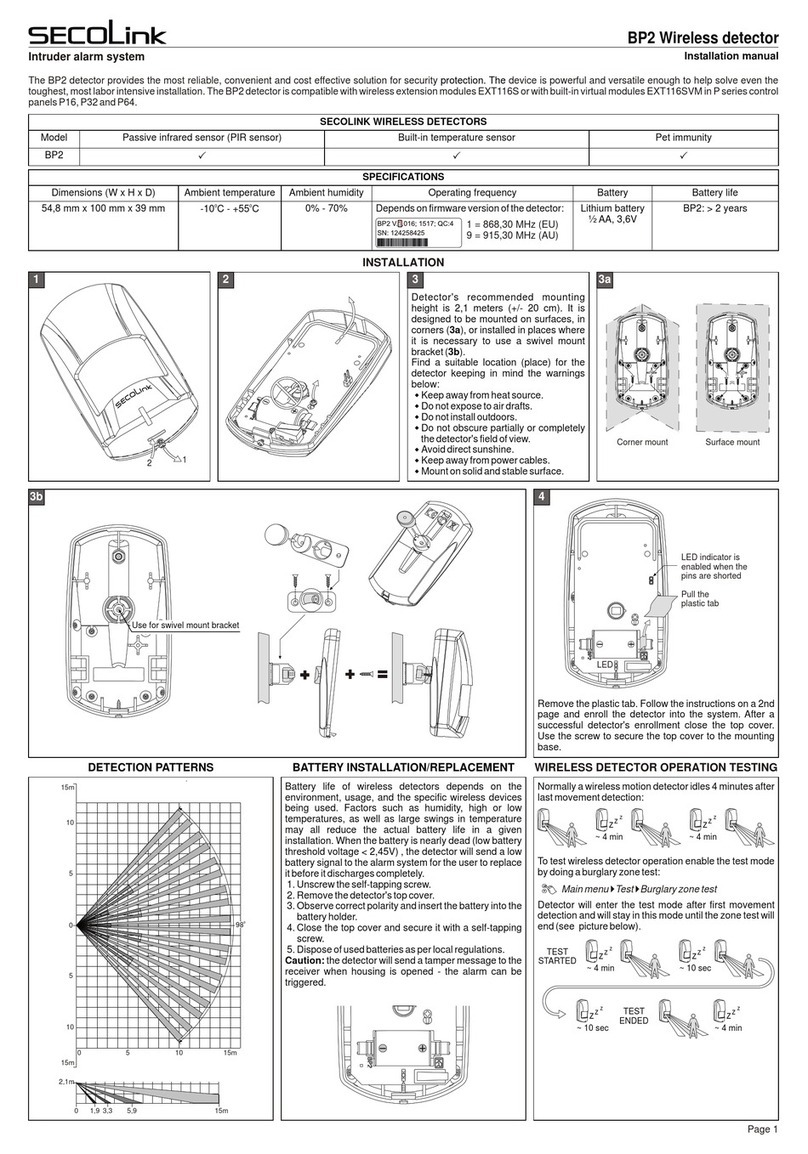
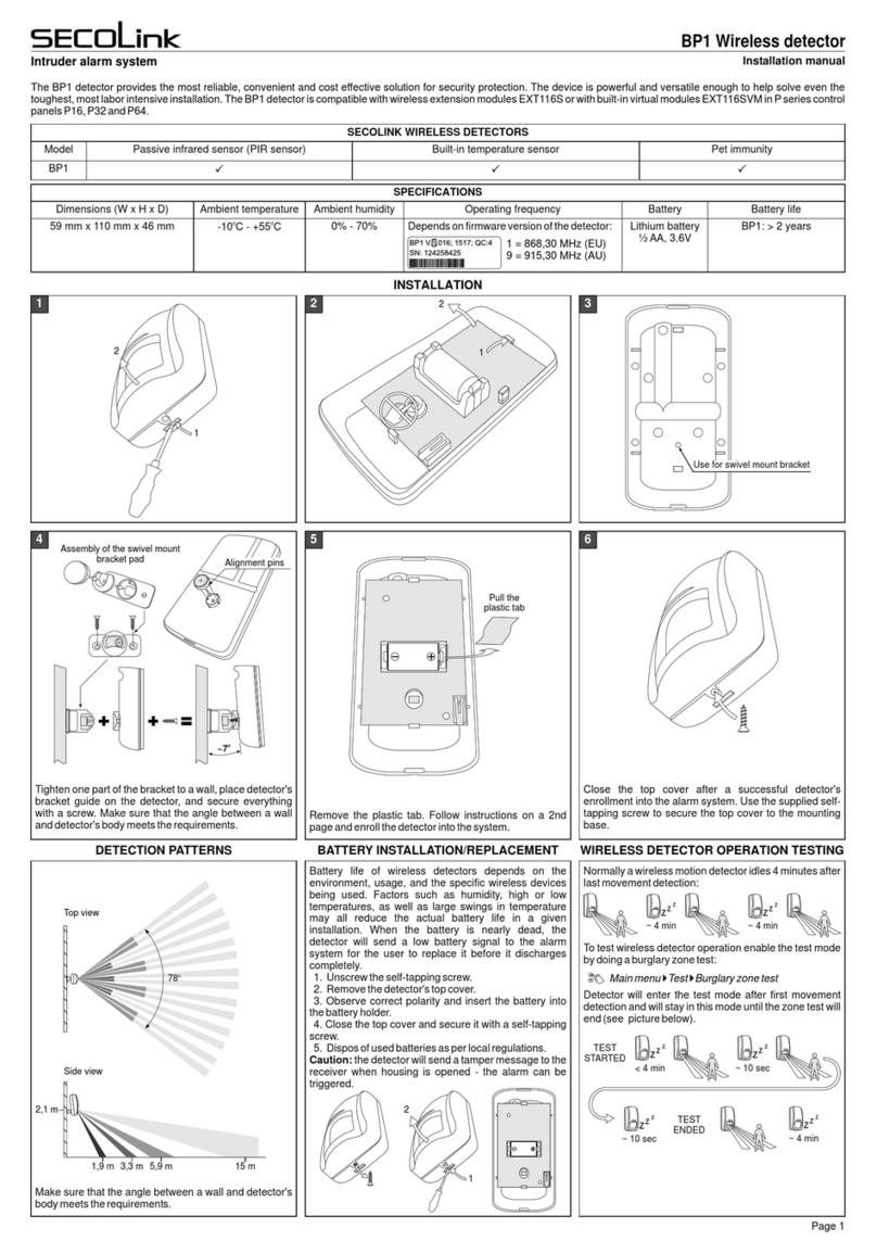
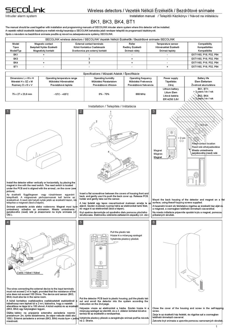
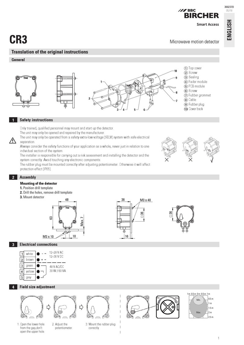
WIRELESS PGM OUTPUT
INSTALATION INSTRUCTION
1. INFORMATION
BS100 – wireless PGM output with an open collector type output
intended to trigger a siren or relay, control gates and etc.
Wireless output operates within the SECOLINK intruder alarm system,
by connecting via the two-way, encrypted protocol to the receiver. The
communication range is up to 100 meters in the premisses. In addition,
the wireless PGM output can be used as part of third-party security
system unit due to the EXT11 module integration.
2. PGM OUTPUT
Connecting a relay:
3. APPLICATIONS
Power supply must be suitable for the siren (+13,8V DC). All jumpers
should be put in positions that allows to trigger the siren by applying
ground (“minus”).
Open collector type output
(up to 50 mA)
Common ground
Power supply
Tamper input
Terminal is used for
backup power supply
Mounting holes x 3 (Ø 3 mm)
Screw
Plastic standoff
Cabinet
BS100
INTRUDER ALARM SYSTEM
Important! Tamper button
and terminal SAB are internally
connected in parallel.
Connecting a siren KR100:
Power supply
(+13,8V DC)
KR100 Vdd
SAB
P
GND
L
S
Batery
Tamper switch
BS100
SL
GND
Vdd
SAB
BAT
+
CAUTION!
DO NOT FORGET TO
CONNECT BATTERY
BEFORE APPLYING POWER
FROM POWER SUPPLY
D1
NC NO
Relay
BS100
Power supply
(+12V DC)
+
Use extra wire and connect GND to
SAB when enrollment is completed.
Starting from firmware version 2.000
tamper function can be disabled.
SL
GND
Vdd
SAB
BAT
It is recommended to
use diode to supress
voltage surges on a
relay.
4. PROGRAMMING
Get into service mode (default PIN codes: first user – 0001, service –
0000):
Main menu }Service Mode }System Setup }Zones
1. Press [7] or [Ų] for a next zone.
2. Give an appropriate name to the zone .
3. Enter the correct zone address in MA_Z format , where MA is a
module address in the system and Z is a zone number in the
module.
4. Enable zone using loop type Wireless
11
12
1
3
Default module address:
4.1. SETTING UP ADDRESS OF THE ZONE
1
2
3
Z01 BS1 0 0
Name
Address
Loop ty pe
12_1
BS100
Wireless
1
1
1
3
1
2
P16-EXT116VM – 12
P32-EXT116VM – 12 and 13
P64-EXT116VM – 12, 13, 14 and 15
EXT116S – 06
4.2. ENROLMENT
Wireless PGM outputs, starting from firmware version 2.000, can be
enrolled in two ways:
by entering serial number and setting up other related settings ;
by entering the Operation code .
4
5
6
8
7
1
2
3
Z01 BS1 0 0
Name
Address
Loop ty pe
BS100
12_1
Wireless
4Seria l No.
Model
PGM out put No. in E XT
Detect tam per
BS100
2
Yes
825
4
5Operatio n code 102
5
TIP! When enrolling, the BS100 must be within range of the
receiver. However, it's still good practice to bring the BS100 as close
to the panel as possible during enrollment.
4.2.1 ENROLMENT USING SERIAL NUMBER
Enrolment using serial number is a two step process:
1 step. Enter BS100 serial number . The keypad will identify the
device type and will show all other related settings that are required
for enrolment .
2 step. SERVICE MODE DOES NOT HAVE TO BE ENTERED AT
THIS STEP! To complete enrolment, the BS100 must be activated to
send a signal to the receiver. It could be done by pressing the tamper
button.
When wireless device is not enrolled all its zones are marked with a
phrase Not activ. in menu Wireless communication.
6
7
8
9
Wireless co mmunicatio n
1
2
3
4
Detector s tat u s
BS100
Windo w
Kitc hen
Livin g room
}Technical information }Wireless communication
Not act iv.
No SN.
LR
only LR
10
11
9
12
When the device is successfully enrolled, the mode LR or ES will be
displayed next to its all zones . Phrase No SN. will be displayed when
wireless zone is enabled, but serial number of the device is not entered
. Phrase only LR will be displayed when the device supports only
the LR mode.
10
11 12
Enter the corresponding peration code and pressO the [ENT] key.
When enrolment has started, immediately press the tamper button for
a short period of time (~1 sec).
5
Operation codes:
4.2.2 ENROLMENT USING OPERATION CODE
First
BS100
102
2
Second
BS100
Third
BS100
Fourth
BS100
103
3104
4105
5

Name
Table 1. Security grade
Supervisory window
1h
0 - 24h (0 = disabled)
Grade 1
Periodic supervision signal
every 1h
Grade 2
Custom
20 minevery 20 min
every 1h
Kodinis Raktas UAB, manufacturer of SECOLINK Intruder Alarm System, offers a Warranty for a term of
twenty-four months. It declares, that product complies with essential EU directives and EU standards EN
50131-1, Grade 1, Environmental Class II; EN 50131-2-2. For more information visit manufacturer’s
website www.kodinis.lt or www.secolink.eu for a complete text of declaration. SECOLINK Intruder Alarm
System is designed and manufactured in Lithuania.
The warranty is given in favor of the purchaser (hereunder the "Purchaser") purchasing the products
directly from Kodinis Raktas UAB (hereunder the "Kodinis Raktas") or from its authorized distributor.
During the warranty period, manufacturer shall, at its option, repair or replace any defective product upon
return of the product to its factory, at no charge for labor and materials. Repaired products shall be
warranted for the remainder of the original warranty period. The Purchaser assumes all responsibility for
the proper selection, installation, operation and maintenance of any products purchased from Kodinis
Raktas or from its authorized distributor. To obtain service under this warranty, please return the item(s) in
question to the point of purchase. All authorized distributors and dealers have a warranty program. All
transportation costs and in-transit risk of loss or damage related, directly or indirectly, to products returned
to Kodinis Raktas for repair or replacement shall be borne solely by the Purchaser. Kodinis Raktas
warranty under this warranty does not cover products that is defective (or shall become defective) due to:
(a) alteration of the products (or any part thereof) by anyone other than Kodinis Raktas; (b) accident,
abuse, negligence, or improper maintenance; (c) failure caused by a product which Kodinis Raktas did not
provide; (d) failure caused by software or hardware which Kodinis Raktas did not provide; (e) use or
storage other than in accordance with Kodinis Raktas specified operating and storage instructions; (f) to
consumable parts, such as batteries or coatings that are designed to diminish over time. There are no
warranties, expressed or implied, of merchantability or fitness of the products for a particular purpose or
otherwise, which extend beyond the description on the face hereof. This limited warranty is the
Purchaser's sole and exclusive remedy against Kodinis Raktas and Kodinis Raktas sole and exclusive
liability toward the Purchaser in connection with the products, including without limitation – for defects or
malfunctions of the products. This warranty replaces all other warranties and liabilities, whether oral,
written, (non-mandatory) statutory, contractual, in tort or otherwise. In no case shall Kodinis Raktas be
liable to anyone for any consequential or incidental damages (inclusive of loss of profit, and whether
occasioned by negligence of the Kodinis Raktas or any third party on its behalf) for breach of this or any
other warranty, expressed or implied, or upon any other basis of liability whatsoever. Kodinis Raktas does
not represent that these products can not be compromised or circumvented; that these products will
prevent any person injury or property loss or damage by burglary, robbery, fire or otherwise; or that these
products will in all cases provide adequate warning or protection. Purchaser understands that a properly
installed and maintained product may in some cases reduce the risk of burglary, fire, robbery or other
events occurring without providing an alarm, but it is not insurance or a guarantee that such will not occur
or that there will be no personal injury or property loss or damage as a result. Consequently, Kodinis
Raktas shall have no liability for any personal injury; property damage or any other loss based on claim
that these products failed to give any warning. If Kodinis Raktas is held liable, whether directly or indirectly,
for any loss or damage with regards to these products, regardless of cause or origin, Kodinis Raktas
maximum liability shall not in any case exceed the purchase price of these products, which shall be the
complete and exclusive remedy against Kodinis Raktas.
Rev.30/09/20
6. SUMMARY
Type
Communication
Compatibility
Output type
Uses
Tamper input
Maximum load
Operating frequency
Wireless
Dual way, encrypted
EXT116VM (panels P16, P32, P64),
EXT116S (system module),
EXT11 (receiver for 3rd party systems)
Open collector type (makes „minus“)
Indoor
Yes (enabled by default)
50 mA / 12V DC
868,30 or 915,30 MHz depending on
the country of distribution
Communication range in
building
Periodic supervision
signal
Operating humidity
Power supply (Vdd)
Current consumption
(without load)
Supervisory window
Operating temperature
up to 100 m
20 min or 1h
up to 70%
+12V DC ± 15% (msg.: “low voltage” < 10V)
standby: ~13mA,
communication: ~25mA
1h ( ),Grade 1
20min (Grade 2),
0 - 24h (Custom)
o
from -10 up to +55 C
Overall dimensions 92 x 22 x 18 mm
SYSTEM COMPLIANCE & WARRANTY
Zone address
(BS100)
PGM output
No. in EXT Operation code
06
06
12
_
_
_
1
8
5
2
3
4
0
0
0
1
1
1
PGM address that
needs to be entered...
06
06
12
_
_
_
2
3
4
2
3
4
Table 3. Examples of PGM address
255
Delete single
254
Delete all
The same Operation code field is used to delete the particular BS100
or all BS100 from the particular module (module supports 4 x BS100):
5
4.3. SUPERVISORY WINDOW
The wireless device periodically sends a supervision signal to a
receiver. If the system does not receive supervision (or alarm signal)
signal from a specific device, the device is regarded as inactive. The
amount of time after which a device is considered inactive is called the
Supervisory window .
13
13
Z01 BS1 0 0
Super v isory wi n dow 1h
7
6. SETTING UP ADDRESS OF THE PGM OUTPUT
Service mode }System Setup }PGM outputs
O04 BS10 0
BS100
06_2
Name
Address
1
18
Burg lary ala rmDefi nition
2
3
CONTACT US
Manufacturer:
Company: UAB “Kodinis Raktas”
Address: Ateities str. 10, 08303 Vilnius, Lithuania
Tel.: +370 675 27275
E-mail: [email protected]
Web: www.secolink.eu
Technical support:
E-mail: [email protected]
Tel.: +370 659 28183
13 _1 13 _55015
1. Press [7] or [Ų] for a next PGM output.
2. Give an appropriate name to an output .
3. Enable PGM output by changing the Definition from Not Used to
any other depending on a specific of use.
4. Enter a wireless PGM output address in MA_P format , where MA
specifies a EXT116S or EXT116VM address in the system (where
BS100 is enrolled) and P specifies the which number was entered in
a OR it is the LAST digit of the field PGM output No. in EXT
Operation code which (see the wireless was used for enrolling
PGM addressing examples in Table ).3
16
17
18
8
5
16
17
5. All other PGM output settings are programmed like usual.
14
Wire less Su bsystem
Gra de 1
1 Secur ity grade
Main menu }Service Mode }System Setup }Wireless Subsystem
Supervisory window and periodic supervision signal sending are
directly related to selected security grade in the system (see Table 1).
14
15
Wire less se tting s
Mode ES (Energy Save)
2
Service mode}System setup}Wireless Subsystem
5. COMMUNICATION MODE SELECTION
Wireless d , starting from version supportevices 2.000 new commu-
nication mode, that can be selected in menu Mode :
15
Mode Distance Battery life
harsh environment for a signal to travel
(ex. concrete walls and ceilings);
long range;
less than 32 wireless devices in the system.
Application
suitable environment for a radio signal
to travel (ex. wooden walls);
middle range;
more than 32 wl. devices in the system;
Table 2. Mode comparison
LR
ES
The conflict can occur when ES is chosen in the system the mode
with older wireless device LR The the s that supports only the mode.
new setting will not be applicable and an error will be displayed on
screen upon changing the mode, on main screen, in the corresponding
user (LT5), wireless zone or module editing menu. All errors will be
displayed until all older wireless devices will be replaced (upgraded)
OR when Mode will be changed back to the LR .
15
15
Other SECOLink Security Sensor manuals
