SECURECOM SC-GSM M2 User manual

SC-GSM M2 manual v2.0 1 EN
S
SC
C-
-G
GS
SM
M
M
M2
2
Alarm system communicators that generate individual SMS
messages and alarm calls via GSM network
from Contact ID reports
Installation manual v2.0

SC-GSM M2 manual v2.0 2 EN
Table of contents
1 General information ........................................................................................................................ 3
1.1 Key features ............................................................................................................................. 3
1.2 Difference compared to the SC-GSM previous model ............................................................ 3
2 Structure .......................................................................................................................................... 4
3 Suggested wiring diagram ............................................................................................................... 5
4 Required setting of alarm panel ...................................................................................................... 5
5 Status signals ................................................................................................................................... 5
6 Settings ............................................................................................................................................ 6
6.1 Standalone mode .................................................................................................................... 7
6.2 Transparent mode ................................................................................................................... 7
6.3 Contact inputs events setting .................................................................................................. 8
6.4 General settings ....................................................................................................................... 8
6.5 Module status window ............................................................................................................ 9
6.6 Latest events window .............................................................................................................. 9
6.7 Administrative window ........................................................................................................... 9
7 Technical data................................................................................................................................ 10
8 Device package content ................................................................................................................ 10

SC-GSM M2 manual v2.0 3 EN
1 General information
The SC-GSM M2 is an alarm system communicator with 2 types of operation.
In standalone mode, it generates an SMS message and an alarm call from Contact ID reports from
alarm control panels or from status changes in its own contact inputs. Operation: it compares the
event codes of the reports from the alarm system (Contact ID) with the event codes predefined in
the program table that require an alarm notification and, when the corresponding event code occurs,
it sends the text assigned to the code as an SMS message to the specified phone numbers or triggers
an alarm call (generating a siren sound). As a result, users can be notified of any alarm event with
individual messages, i.e. not only the fact of the alarm, but also its location can be specified in the
SMS message, and the user's activity - e.g. opening/closing - can be tracked by name.
In transparent mode, the device is capable of GSM voice calls with phone line simulation. The device
can connect the alarm system to the user via a mobile call or can be used as a simple phone line in
other applications in places where a public phone line is not available (lifts, SOS or INFO call points,
holiday homes, etc.) The device does not handle incoming calls and cannot ring the connected phone
line device.
1.1 Key features
2 separate operating modes in one device
Telephone line simulation for alarm TIP/RING communicator
Send SMS and alarm calls based on up to 64 Contact ID codes
Notification to 4 user phone numbers
2 contact inputs, with independent signaling
SMS forwarding to the specified phone number
Setup and diagnostics via USB connection
1.2 Difference compared to the SC-GSM previous model
Instead of 32 events, 64 Contact ID events can be notified
The timing settings for the notification can be freely parameterized
Extended event log, every detail of the communication can be monitored
No USB back-up memory
No possibility to ring out on incoming calls
The device programming software has changed

SC-GSM M2 manual v2.0 4 EN
2 Structure
❶ TIP/RING Communication terminals, generated phone line output
Simulated PSTN line for connection to TIP/RING alarm panel input terminals
❷ Power supply terminals
Power requirements: DC 9-30V / 300mA
❸ Alarm contact inputs
Triggered to negative supply (with dry contact)
❹ SIM card holder
Type: 2FF/mini SIM
❺ USB mini B connector for configuration
❻ GSM antenna connector, SMA type
❼ Status signaling LEDs

SC-GSM M2 manual v2.0 5 EN
3 Suggested wiring diagram
4 Required setting of alarm panel
The connected alarm panel must have following settings:
– Phone communication should be enabled in the alarm centre
– DTMF (Tone) dialing should be selected
– A minimum 4 digit phone number should be set for dialing (anything is acceptable, e.g. 1111)
– Object identifier should be set
– Contact ID (Full) should be selected
The device will accept the Contact ID reports from alarm panel as a monitoring receiver, and forward
them to IP monitoring receiver. Only after the reporting was acknowledged by monitoring station,
the acknowledge signal will be transmitted to alarm panel.
5 Status signals
With the status LED ❼, the device can display these basic statuses.
Signals Device status
Flashing RED Connecting to network / SIM or network failure after 1 minute
Flashing GREEN Idle state ( Device is ready, waiting for report from alarm panel)
Continuous GREEN Communication with alarm panel in progress
Flashing RED & GREEN Low signal strength, below 30%

SC-GSM M2 manual v2.0 6 EN
6 Settings
To set up the device install the SECURECOM CONFIGURATOR software. The installation file
(securecomconfiguratorsetup.exe) is available on securecom.eu web site. Run the installer, it will
make the software available from the start menu.
After running the program, connect the USB port of the device to the
PC, and select the appropriate serial port, then push the “Connect” button. For example:
Once connected, device settings can be found on the following interface.
Attention: To validate the changes, settings must be downloaded into device!
Downloading of settings is performed with icon. The latest events panel will show the changes.
When any parameter value is changed in software, the background color of icon becomes red,
showing that the displayed values are not the valid ones (in the device), so they should be
downloaded.

SC-GSM M2 manual v2.0 7 EN
6.1 Standalone mode
This mode can be selected in the Operation mode field of the GENERAL SETTINGS window. This
mode is used to send notifications and information from alarm panel directly to USERS. When the
alarm panel transmits any Contact ID event Code to communicator (through emulated phone line on
RING/TIP terminals), the device simulates a monitoring receiver, accepts the code and confirms the
event reception to alarm panel. After that, the received Code is compared to all codes set in the
„event filter” table, and if it exists in the table, the communicator makes the notification procedure-
starts a voice call or sends SMS messages to selected user numbers (1-4).
During communication, the communicator expects signals according to the Contact ID standard.
Contact ID messages are structured as follows:
Account number:
4 character
Protocol ID
18
Event Qualifier
Event= 1
Restore= 3
Event Code
3 character
Group/Partition
2 character
Zone or USER
3 character
e.g. 1234 18 1 130 01 001
The first 6 characters of the Contact ID code (Account number and Protocol ID) are ignored by the
event filter. The other characters must be entered in the event filter table according to the expected
event. If Partition and Zone/User are not filled in, SMS and Call notifications are always sent when an
event occurs, thus the filter does not take into account the Zone and Partition values.
To trigger an SMS message and alert CALL for a given event, you need to select the phone numbers
to be notified and enter the text of the SMS to be sent. These can be entered in the event filter table
in the event row to be notified.
The telephone numbers of the persons to be notified can be entered in the PHONE NUMBER
SETTINGS window, up to a maximum of 4 telephone numbers, with an acknowledgement option to
be ticked if necessary. By setting the acknowledgement, the communicator will continue to call the
telephone number until the customer presses any number (0-9) on the telephone keypad during the
siren. At that point the device will know that the alarm has been received. If the alarmed person does
not acknowledge the alarm, the telephone number will be dialed until the alarm duration specified in
the GENERAL SETTINGS window.
6.2 Transparent mode
The mode can be selected in the Operation mode field in the GENERAL SETTINGS window.
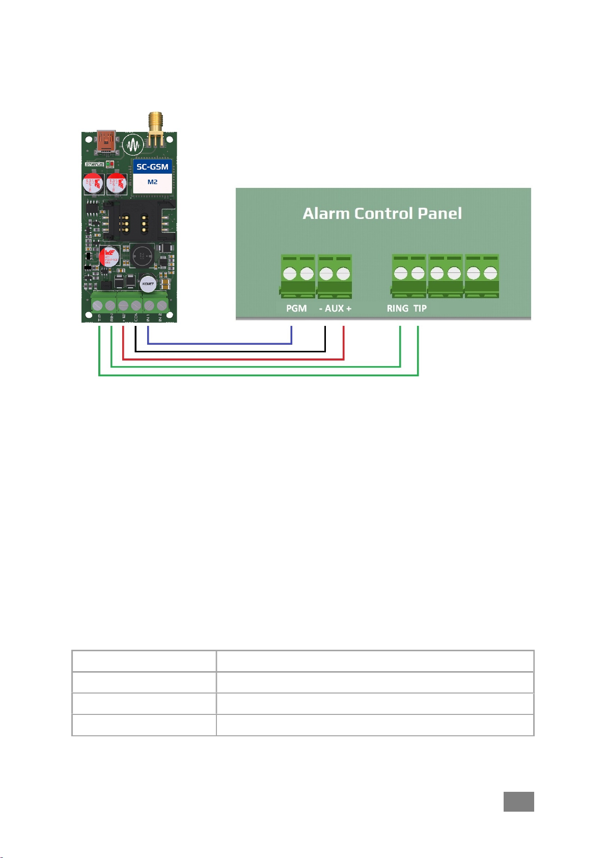
In transparent mode, the device acts as a direct PSTN-GSM gateway. The voice signals of connected
analog phone device or alarm panel (siren or tone signals) are transmitted via the GSM network to
the called user telephone number. The alarm panel (or analog phone) connected to the RING/TIP
outputs dials the calling number and the communicator establishes the voice channel through which
all voice signals are transmitted via the GSM network. The device does not handle the incoming call,
so it cannot ring the connected telephone line.

SC-GSM M2 manual v2.0 8 EN
6.3 Contact inputs events setting
The device has 2 contact inputs, with NO or NC setting. For alarm notifications, the contacts must be
connected to the DC - negative supply voltage. Sensitivity means that the event (short circuit or
interruption) that triggers the alarm must persist for at least the time set there. In case of a contact
event, the alarm device shall notify the selected telephone numbers by means of an alarm call
and/or SMS message. The SMS message can be specified individually.
6.4 General settings
In this window you can change the parameters related to the operation of the communicator.
SIM PIN: the PIN code of the inserted SIM card must be entered if PIN code request is set
Ringing time: ringing time of the called phones in seconds (for limiting voicemail)
Call time: the siren time on the called telephone in seconds
Alarm time: event notification expiry time in seconds
SMS limit: daily limit for sending SMS
Call limit: daily limit for alarm calls
Operation mode: mode selector for the desired use (as mentioned above)
Test SMS period: frequency of periodic test report that the unit works properly
Test SMS text: message of periodic test report that the unit works properly

SC-GSM M2 manual v2.0 9 EN
6.5 Module status window
This window shows the operational status of the communicator.
6.6 Latest events window
In this window, you can monitor the communication between the communicator and the alarm
system, the sending of notifications to the user's phones and the current error messages from the
device.
6.7 Administrative window
The administration window of SecurecomConfigurator contains the following basic information
about the device.
The function of the administration icons is as follows:
Type of connection and operator name
Mobile network signal strength (0-100)
Control status of inputs
Alarm panel dialer status
Supply voltage value
Network date
and time
Product type ID
Microcontroller program version
Administrative tools
Language selection
Open and load saved settings to the screen
Save settings to file
Save the configurator screen settings into the device memory

SC-GSM M2 manual v2.0 10 EN
7 Technical data
Network connection GSM(2G) GSM850MHz/EGSM900MHz/DCS1800MHz/PCS1900MHz
Supply voltage: 9 V - 30 V DC
Rated current 100 mA
Maximum current 300 mA
Operating temperature -20°C - +70 °C
Dimensions 40x80x15 mm
8 Device package content
• SC-GPRS M2 communicator
• Antenna
• USB cable
• Plastic pegs
• Warranty
Table of contents
Other SECURECOM Cell Phone manuals