Securitron EcoPower EPS-05 User manual
1 500-33530, Rev B
EcoPower™ Power Supply
Owner’s Manual

2 500-33530, Rev B
Table of Contents
Warranty....................................................................................................2
Models.......................................................................................................3
Structure....................................................................................................3
Block Diagram...........................................................................................4
Specifications............................................................................................4
Environmental .......................................................................................4
Mechanical ............................................................................................5
Electrical................................................................................................5
Regulatory Certifications .......................................................................6
Regulatory Compliance.........................................................................7
UL294 Access Control Performance Levels for Model EPS-05
Power Supply ........................................................................................7
Status Signaling ....................................................................................8
Access Control and FAI Operations..........................................................8
Installing the EcoPower Power Supply...................................................11
Install the EcoPower Power Supply using the included enclosure
box (flush with the wall stud and wall surface)....................................11
Install the EcoPower Power Supply using the included enclosure
box and surface mounted....................................................................15
Install the EcoPower Power Supply flush with the stud in an
existing 2-gang junction box................................................................17
Warranty
The EcoPower™ Power Supply is covered by the MagnaCare®lifetime
replacement no fault warranty. No registration is required. Product will
be replaced forever, for any reason, including but not limited to installation
error, vandalism, or act of God. Replacement product is shipped at
Securitron’s expense next day air if needed.
For more information, visit www.securitron.com

3 500-33530, Rev B
Models
EPS-05 EcoPower Power Supply in Enclosure
EPS-05B EcoPower Power Supply PCB only
Structure

4 500-33530, Rev B
Block Diagram
Specifications
Environmental
Parameter Value
Operating Ambient Temperature 0 to +49° Celsius (C)
Design Product Life 10 years, +49°C ambient,
continuous full load
Storage Temperature -25 to +85°C
Operating Humidity 5 to 90%, non-condensing

5 500-33530, Rev B
Mechanical
Parameter Value
Enclosure Polycarbonate, UL294 Level 1
Enclosure dimensions 4 1/8” X 4 1/8” X 3 13/16”
AC input wiring 3-wire with strain relief
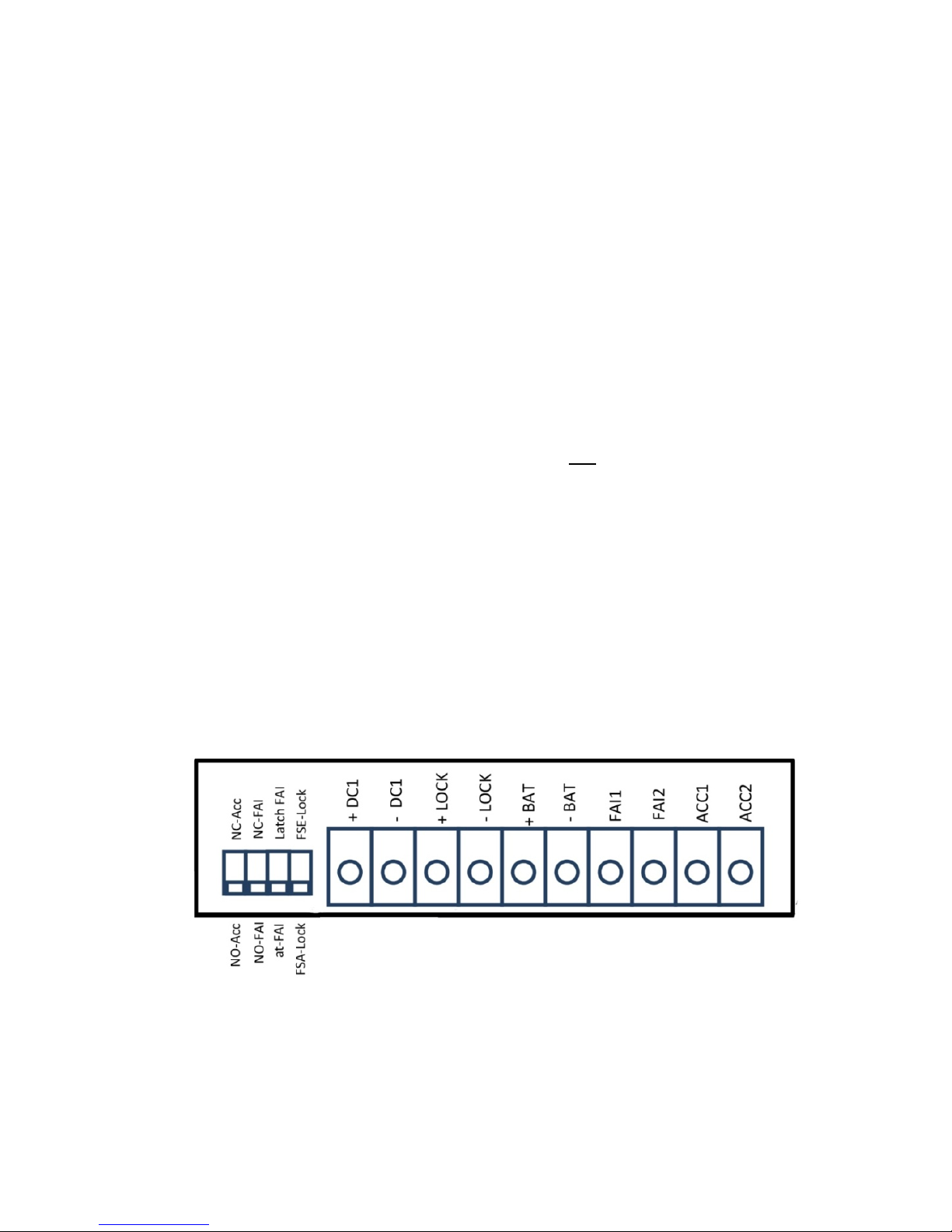
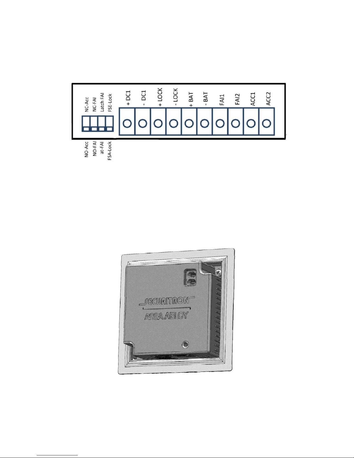
DC1, LOCK, BAT, FAI, ACC wiring 10-position terminal strip
Electrical
Parameter Value
Input Voltage Range 100–240 VAC, ±10%
Input Frequency 50–60 Hz
Input Surge Resistance 6000 Vpk
Access Control Input Dry Contact, NO or NC; 32
VDC, 0.02A minimum
Fire Alarm Interface Input Dry Contact, NO or NC; 32
VDC, 0.02A minimum
Hi-Pot Test 2500 VAC or 3535 VDC
Leakage Current < 0.5 mA
Output Voltage at No Load Set to 14.0 VDC, ± 0.2%
Number of Outputs Two (2) Outputs:
DC1 (Reader): 12 VDC nominal
(9.4–14.6 VDC for compatibility)
LOCK: 12 VDC nominal (9.4–
14.6 VDC for compatibility)
If the battery is discharged
below 9.4V, the lock output is
de-energized
Total Peak Output Current 0.5A (Total current from both
outputs for at least 1 second)
Total Continuous Output Current 0.1A (Total continuous current
from both outputs)
Charging Current (BAT) 12 VDC nominal, 0.1A
maximum continuous, 0.34A
peak (< 2 seconds)
Standby Power < 20 mW at 230V, < 10mW
at115V
Load Regulation < 2.5% at 100 mA
Line Regulation < 0.2%

6 500-33530, Rev B
Output Voltage Ripple and Noise < 0.14 Vpp (20 MHz bandwidth
limit measurement)
Output Surge Resistance 2400 Vpk
Output Over Voltage Protection Under any single point
condition, output voltage shall
not exceed 120% of nominal
voltage
Battery Type and Capacity Sealed Lead Acid (SLA), 12V,
0.8 Ah
Battery Standby Time 20.5 hours dependent on lock
type (FSA or FSE) and usage.
Battery standby time is
designed for EcoFlex lock with
optional H1 controller only (not
for 100 mA load). H1 controller
draws an average of 5 mA.
The two total current draw is
about 20 mA.
Total Load Current 0.8 Ah Battery Backup Time
20 mA 20.5 hours
50 mA 6.5 hours
100 mA 2 hours
Regulatory Certifications
•UL294, "Access Control System Unit," 6th Edition
•UL603, "Power supply for use with Burglar Alarm System," 5th
Edition
•CAN/ULC-S533, "Egress Door Securing and Releasing Devices,"
3rd Edition
•GreenCircle Certified (99% Energy Savings)
NOTE: 50% - battery discharge time from fully charged
condition.

7 500-33530, Rev B
Regulatory Compliance
•EN60950-1:2006+A11:2009+A1:2010+A12:2011, "Information
Technology Equipment–Safety”
•FCC Part 15, Subpart B, "(unintentional radiator), Class A for
industrial and commercial use"
•EN55022:2010, "Class A for industrial and commercial use”
•EN55024:2010
•EN61000-3-2:2006+A1:2009+A2:2009
•EN61000-3-3:2008
•CE LVD and EMC directives currently in effect
•EU RoHS Directive
•EU REACH Regulation
UL294 Access Control Performance Levels for Model
EPS-05 Power Supply
NOTE: Without an attack-resistant enclosure, the EPS-05 cannot
power Mercantile, Bank Safe and Vault audible alarm
devices or Digital Alarm Communicator Transmitters
(DACTs).
Access
Control
Line
Security
Destructive
Attack Endurance Standby
Power
Example Conditions
and Notes
I I IV IV
Standby Power Level
IV when used with
Ecoflex Lock and H1
Controller

8 500-33530, Rev B
Status Signaling
Green LED Signaling AC Power Mode: Solid on
AC Standby Mode: 2s on / 2s off
AC Lost Mode: 1s on / 2s off
Output Voltage Abnormal: OFF
Battery Disconnected: Rapid flash (4 times per
second, then off for 1 second)
NOTE: Black text indicates condition; green text
indicates corresponding LED lighting pattern.
Red LED Signaling Power Supply Alarm Mode: ON
Power Supply Normal Mode: OFF
Output Voltage Abnormal: Blink at 1 Hz
Battery Discharged Below 9.6V: Blink at0.5 Hz
NOTE: If alarm has occurred and FAI set to
latch mode, power supply stays in alarm mode
until the reset button on the front panel is
pressed.
Buzzer Beep at 1/3 Hz for 30 seconds every 15 minutes
NOTE: Reset battery by pressing the reset
button on front panel for 5 seconds to silence
alarm for 24 hours.
Access Control and FAI Operations
The following table describes how the lock power output (DC2) responds
to the access control input under various DIP switch settings. This table
is only valid when the EcoPower has not received a fire alarm activation
signal at the FAI input.
Access Control
Input DIP Switch Settings Output
Access Dry
Contact State
Access DIP
Switch
Setting
Lock Type DIP
Switch Setting
LOC
K
Output
Voltage
FAI LED
(RED)
Open NO Fail-Safe (FSA) On Off
Open NO Fail-Secure (FSE) Off Off

9 500-33530, Rev B
Access Control
Input DIP Switch Settings Output
Access Dry
Contact State
Access DIP
Switch
Setting
Lock Type DIP
Switch Setting
LOC
K
Output
Voltage
FAI LED
(RED)
Open NC FSA Off Off
Open NC FSE On Off
Closed NO FSA Off Off
Closed NO FSE On Off
Closed NC FSA On Off
Closed NC FSE Off Off
NOTE: Because the lock circuit fails secure, listed panic hardware
shall be used to allow emergency exit from the protected
area.
The following table describes lock power output behavior when there is
an active fire alarm signal at the FAI input. This ensures the door is
unlocked when there is an active fire alarm signal. It should be noted
that the FAI signal will always override the access control signal.
FAI Signal DIP Switch Settings Output
FAI Dry Contact
State
FAI DIP
SW
Setting
Lock Type DIP SW
Setting
LOCK
Output
Voltage
FAI LED
(RED)
Open NC FSA Off On
Open NC FSE On On
Closed NO FSA Off On
Closed NO FSE On On
10 500-33530, Rev B
NOTE 1: Unit should only be connected to a fire alarm panel when
used in a FSA configuration.
NOTE 2: If the DIP switch for FAI latching is set to the “Latched”
Position, the LOCK output and the red LED will remain in fire
alarm state even when an active FAI input is removed. The
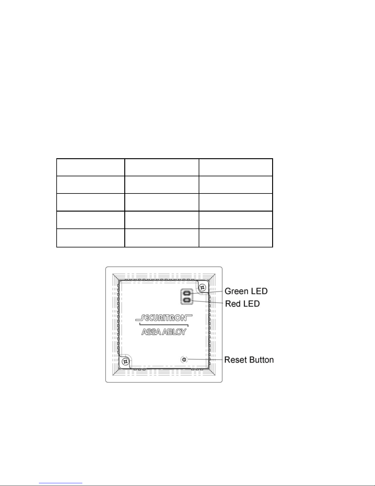
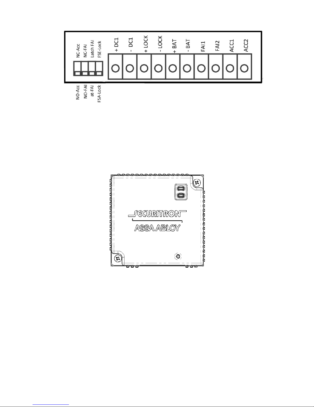
user will need to depress the reset button on the bottom right
of the front panel for 1 second (see Figure 1, “Reset Button
and LED Locations”) to reset the fire alarm state (red LED off
and lock per access control input). The factory default DIP
switch settings are as follows:
DIP Switch Name Default Position Notes
Access control input Normally Open (NO) Normally Closed (NC)
FAI input NO NC
FAI Latch FAI Latching Disabled FAI Latching Enabled
Lock Type Fail-Safe (FSA) Fail-Secure (FSE)
Figure 1: Reset Button and LED Locations

11 500-33530, Rev B
Installing the EcoPower Power Supply
NOTE 1: Installation should be performed by a qualified service
person, who conforms to all local codes and complies with
The National Electrical Code (or equivalent).
NOTE 2: The EcoPower Power Supply can be installed in either a
standard, existing 2-gang junction box (flush with the wall
stud), or the included enclosure box (flush with the wall stud
and drywall surface), or an enclosure surface mounted on
the wall.
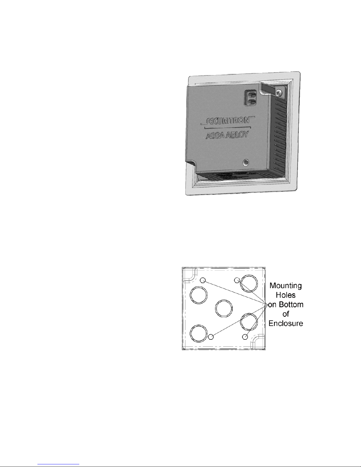
Install the EcoPower Power Supply using the included
enclosure box (flush with the wall stud and wall surface)
NOTE: Due to the location of the conduit knockouts on the included
plastic enclosure, the EcoPower Power Supply will finish with a
flush mount look.
1. DETERMINE location to mount the EcoPower Power Supply.
2. CUT a 4 5/8” by 4 5/8” hole in drywall.
12 500-33530, Rev B
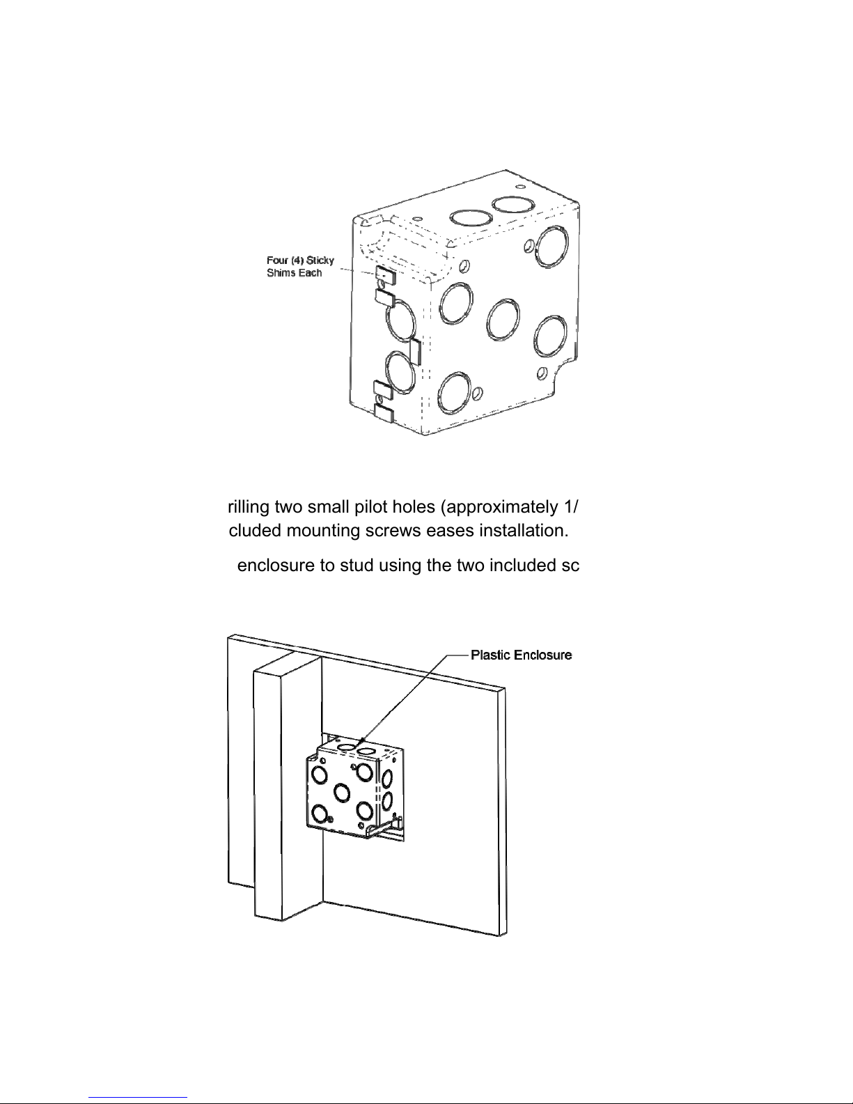
3. PLACE sticky shims on the side of the enclosure to be mounted to
the stud.
NOTE: Drilling two small pilot holes (approximately 1/16”) for the
included mounting screws eases installation.
4. MOUNT enclosure to stud using the two included screws.
13 500-33530, Rev B
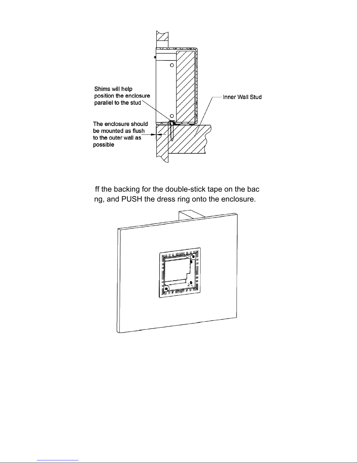
5. PEEL off the backing for the double-stick tape on the back of the
dress ring, and PUSH the dress ring onto the enclosure.
14 500-33530, Rev B
NOTE 1: It is recommended that the conduit be installed on the top and
bottom of the enclosure box for wiring and the battery be
installed horizontally.
NOTE 2: These products are intended to be installed with conduit
fittings in the field. Connections should be used that are
compatible with the Type 1 rated enclosure.
6. ENSURE wire conduit is connected to the junction box with strain
relief.
NOTE 1: The battery may be oriented in the junction box either vertically
or horizontally as long as the connection wires from the battery
and power supply module have a clear pathway to the
attached wire conduits.
NOTE 2: If the included battery/battery-type is not used, fish paper must
be used to provide insulation for the installed battery.
7. INSTALL the battery into the junction box.
8. (Optional) REMOVE the power supply module from the cover to
ease in connection of wiring.
NOTE: Wiring must be Class 1.
9. CONNECT the access control device, access control panel, fire
alarm interface, battery, and lock wiring to the power supply module
terminals.
10. (Optional) INSTALL the power supply module back into the cover,
ensuring the LEDs are facing out at the top right, and SECURE with
the two installation screws.
15 500-33530, Rev B
11. CONFIGURE the dipswitch settings as needed for your application.
12. CONNECT AC mains power and Earth Ground, and Earth Ground
connections so continuity is maintained.
13. MOUNT the cover to the
enclosure using the two
captive screws.
Install the EcoPower Power Supply using the included
enclosure box and surface mounted
1. DETERMINE location to mount the EcoPower Power Supply.
2. MARK the positioning of the
4 enclosure mounting holes
on the drywall surface.
3. CUT holes for conduit, if
needed.
16 500-33530, Rev B
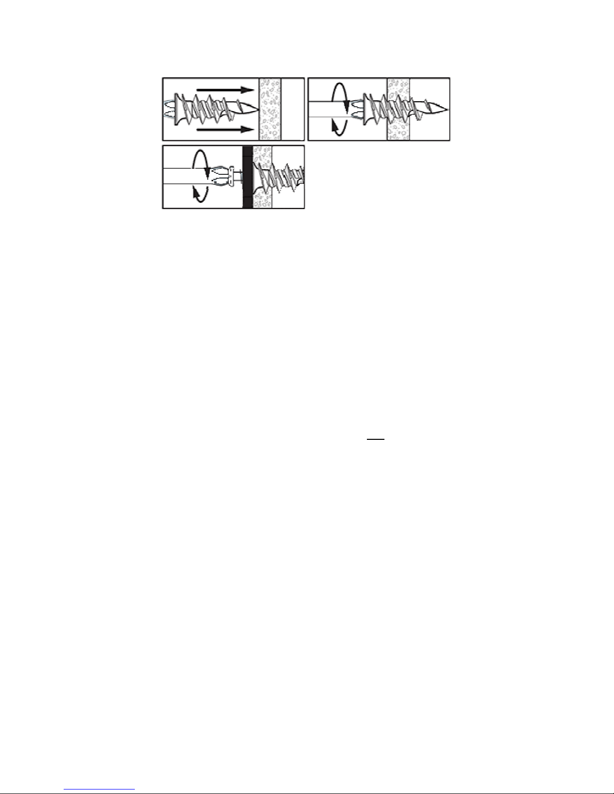
4. ATTACH appropriate drywall anchors (one example shown).
5. MOUNT enclosure box to drywall using the screws to attach it to the
drywall anchors.
NOTE: It is recommended that the conduit be installed on the top and
bottom of the enclosure box for wiring and the battery be
installed horizontally.
6. ENSURE wire conduit is connected to the enclosure with strain relief.
NOTE 1: The battery may be oriented in the junction box either vertically
or horizontally as long as the connection wires from the battery
and power supply module have a clear pathway to the
attached wire conduits.
NOTE 2: If the included battery/battery-type is not used, fish paper must
be used to provide insulation for the installed battery.
7. INSTALL the battery into the junction box.
8. (Optional) REMOVE the power supply module from the cover to
ease in connection of wiring.
NOTE: Wiring must be Class 1.
9. CONNECT the access control device, access control panel, fire
alarm interface, battery, and lock wiring to the power supply module
terminals.
17 500-33530, Rev B
10. (Optional) INSTALL power supply module back into the cover and
SECURE with two installation screws.
11. CONNECT AC mains power and Earth Ground, and Earth Ground
connections so continuity is maintained.
12. MOUNT the cover to the junction box using the two captive screws.
Install the EcoPower Power Supply flush with the stud in
an existing 2-gang junction box
NOTE: Due to the location of the conduit knockouts on a standard
junction box, the EcoPower Power Supply will finish with a
slightly recessed look.
1. DETERMINE location to mount the EcoPower Power Supply.
2. WIDEN the junction box (drywall) cutout to 4 5/8” by 4 5/8”

18 500-33530, Rev B
3. PEEL off the backing for the double-stick tape on the back of the
dress ring, and PUSH the dress ring onto the junction box.
NOTE: It is recommended that the conduit be installed on the top and
bottom of the enclosure box for wiring and the battery be
installed horizontally.
4. ENSURE wire conduit is connected to the junction box with strain
relief.
NOTE 1: The battery may be oriented in the junction box either vertically
or horizontally as long as the connection wires from the battery
and power supply module have a clear pathway to the
attached wire conduits.
NOTE 2: If the included battery/battery-type is not used, fish paper must
be used to provide insulation for the installed battery.
5. INSTALL the battery into the junction box.
6. (Optional) REMOVE the power supply module from the cover to
ease in connection of wiring.
19 500-33530, Rev B
NOTE: Wiring must be Class 1.
7. CONNECT the access control device, access control panel, fire
alarm interface, battery, and lock wiring to the power supply module
terminals.
8. (Optional) INSTALL the power supply module back into the cover,
ensuring the LEDs are facing out at the top right, and SECURE with
the two installation screws.
9. CONNECT AC mains power and Earth Ground, and Earth Ground
connections so continuity is maintained
10. MOUNT the cover to the junction box using the two captive screws.

20 500-33530, Rev B
Securitron
Phoenix, AZ
Tel: 1.800.624.5625
Mon-Fri: 6:00am - 4:00pm PDT
Fax: 1.800.232.7329
www.securitron.com
techsupport@securitron.com
©
2015, Hanchett Entry Systems, Inc., an ASSA ABLOY Group Company.
This manual suits for next models
1
Table of contents
Other Securitron Power Supply manuals

Popular Power Supply manuals by other brands


Altronix
Altronix eFlow104NK8QP installation guide

Altronix
Altronix ALTV2432UL3 Series installation guide

Huawei
Huawei TP48200A-DT19D1 Telecom Power user manual

Puls
Puls PIANO Series manual

Matsusada Precision
Matsusada Precision PRKT Series instruction manual

VOSS.farming
VOSS.farming HELOS 4 instruction manual


