manuals.online logo
Brands
  1. Home
  2. •
  3. Brands
  4. •
  5. ADTRAN
  6. •
  7. Power Supply
  8. •
  9. ADTRAN D4PBCU0 Maintenance and service guide

ADTRAN D4PBCU0 Maintenance and service guide

Page 1
Section 61150.052L1-5, Issue 1
Part No.
1150052L1
61150.052L1-5A
Section 61150052L1-5
Issue 1, July 1995
CLEI Code # D4PBCU0_ _ _
MODEL ACT PSU
ADVANCEDCOMMUNICATIONS TERMINAL
POWER SUPPLY UNIT
INSTALLATION/MAINTENANCE
PRACTICES
CONTENTS
1. GENERAL .....................................................................1
2. INSTALLATION ............................................................1
3. CONNECTIONS ............................................................2
4. FACEPLATE INDICATORS .........................................2
5. MAINTENANCE ............................................................2
6. WARRANTY AND CUSTOMER SERVICE ..................2
FIGURES
Figure 1. ADTRAN ACT PSU ...........................................1
Figure 2. Connector Pin Assignments...........................2
TABLES
Table A. Basic Features .................................................1
Table B. ACT PSU Specifications..................................2
Table C. Faceplate Indicators ........................................2
C A U T I O N !
SUBJECT TO ELECTROSTATIC DAMAGE
OR DECREASE IN RELIABILITY.
HANDLING PRECAUTIONS REQUIRED.
Unit
ACT PSU
Features
Fuses incoming -48 V and 20 Hz
ringing voltage.
Converts -48 VDC to regulated +5
VDC, +12 VDC, and -12 VDC.
Outputs individually diode
isolated to allow redundant
operation.
Front panel test points for all
voltages.
Front panel indicators showing
the status of the unit.
Filters -48 V to provide -48 F for
the rest of the system.
Table A. Basic Features
1. GENERAL
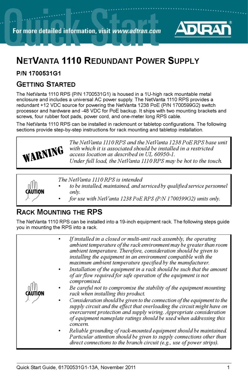
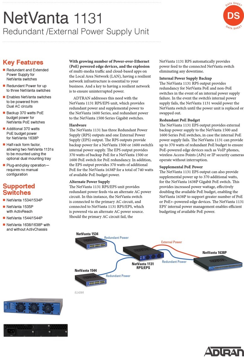
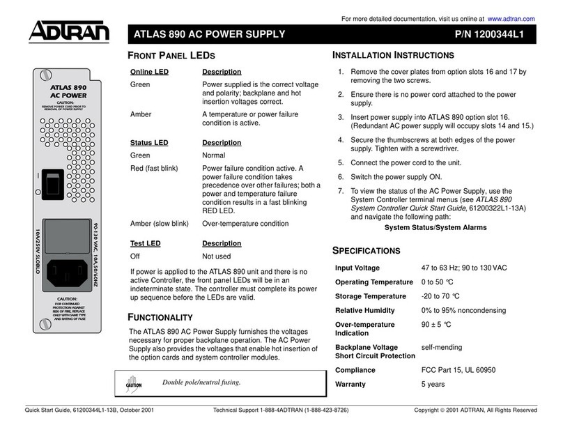
1.1 This practice provides installation and mainte-
nance information for the ADTRAN Advanced
CommunicationsTerminalPowerSupplyUnit(ACTPSU).
Figure 1 is a drawing of the unit. A detailed product
description and specifications can be found in the
ADTRAN ACT PSU Description Practice, Section
61150052L1-2. The part number and basic features for
the unit are provided in Table A. The specifications for
the ACT PSU are shown in Table B.
1.2 Revisions to this practice will be summarized in
this paragraph.
1.3 The ADTRAN ACT PSU is a common module
plug-in used in the ACT 2300, 1900, and 1950 channel
banks. The unit converts the -48 VDC input to +5 VDC,
+12VDC, and -12 VDC outputvoltage levels to beused
byothercommonequipmentandchannelunits. Theunit
is also designed to operate in a parallel, redundant
fashion for increased system reliability.
Figure 1. ADTRAN ACT PSU
2. INSTALLATION
2.1 Inspecttheunitforshipping damageimmediately
after unpacking it. If damage is discovered, file a claim
immediately with the carrier; then contact ADTRAN
Customer Service (see subsection 6.2).
2.2 The ACT PSU plugs directly into the common
cardareainthepositionsmarkedPOWERSUPPLYAor
POWER SUPPLY B. To install the ACT PSU, grasp the
unitbythefaceplateandpushitfirmlyintothebackplane
connectoruntiltheunitisseated. Locktheunitinposition
using the two faceplate screws.
2.3 TherearenoadjustmentsoroptionsfortheACT
PSU.
Page 2
Section 61150.052L1-5, Issue 1
4. FACEPLATE INDICATORS
TableCshowsthestatusindicatorsforincoming
power, ringing voltage, and outgoing voltages.
-42.25 VDC to -56.00 VDC,
-48 VDC, nominal
3.0 A
0 Vrms to 120 Vrms
105 Vrms, nominal
0.25 A
+5 VDC ±5%
4 A, maximum
+12 VDC ±10%
1 A, maximum
-12 VDC ±10%
1 A, maximum
-42.25 V to -56.00 V
2 A, maximum
0 to 120 Vrms
105 V, nominal
0.25 A, maximum
DC Voltage
Current
Ringing Voltage
Current
+5 V
+12 V
-12 V
-48 V filtered
20 Hz
Input
Output
Table B. ACT PSU Specifications
Figure 2. Connector Pin Assignments
901 Explorer Boulevard • Huntsville, Alabama • 35806-2807 • (205) 971-8000 • FAX (205) 971-8699
3. CONNECTIONS
3.1 Figure 2 shows the ACT PSU connector pin
assignments. Allinputs andoutputstothe ACTPSUare
made through the backplane. No additional backplane
wiring is necessary for normal operation.
Indicator
PWR ON,
20 HZ ON
PWR FAIL
Description
Indicator turns
On
whenever incoming
power or ringing voltage is present.
Indicator turns
On
whenever one of the
outgoing voltages of the individual PSU has
failed.
Table C. Faceplate Indicators
5. MAINTENANCE
5.1 The ACT PSU requires no routine maintenance
to operate properly.
The faceplate has two faceplate fuses. If a fuse
blows,acoloredpinbecomesvisiblefromthefrontofthe
channel bank. To remove a fuse, grasp it and firmly pull
itfrom theholder. Toinsertafuse, pushitintothe holder
until it firmly seats.
5.2 ADTRAN does not recommend that repairs be
performed in the field. Repair services may be obtained
by returning the defective unit to the ADTRAN Repair
Department (see subsection 6.2).
6. WARRANTY AND CUSTOMER SERVICE
ADTRANwillreplaceorrepairthisproductwithin
five years from the date of shipment, if the product does
not meet its published specifications or if it fails while in
service. For detailed warranty, repair, and return
information, refer to the ADTRAN Equipment Warranty
and Return Policy Procedure.
6.1 ReturnMaterialAuthorization(RMA)isrequired
prior to returning equipment to ADTRAN.
6.2 Forservice,RMArequests,orfurtherinformation,
contact one of the following numbers.
ADTRAN Customer Service:
RMA (205) 971-8722
Technical Support (800) 726-8663
Applications Engineering (800) 615-1176
Sales (800) 827-0807
Repair and Return Address:
ADTRAN, Inc.
Customer Service Department
901 Explorer Boulevard
Huntsville, Alabama 35806-2807
28
29
30
31
32
33
34
35
36
37
38
39
40
41
42
43
44
45
46
47
48
49
50
51
52
53
54
1
2
3
4
5
6
7
8
9
10
11
12
13
14
15
16
17
18
19
20
21
22
23
24
25
26
27
TPSS
TSPV
RSPV
PFAIL
20 Hz FUSED
20 Hz IN
GND
GND
- 12 V
+ 12 V
GND
GND
+ 5 V
+ 5 V
- 48 F
- 48 F
- 48 V
- 48 V
- 48 V IN
- 48 V IN
FRM GND
MAD0
MAD1
MAD2
20 Hz FUSED RET
20 Hz IN RET
GND
GND
- 12 V
+ 12 V
GND
GND
+ 5 V
+ 5 V
- 48 FRT
- 48 FRT
- 48 VRT
- 48 VRT
- 48 IN RT
- 48 IN RT
FRM GND

This manual suits for next models

1

Other ADTRAN Power Supply manuals

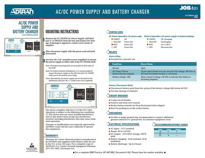
ADTRAN NetVanta 1131 RPS/EPS User manual

ADTRAN

ADTRAN NetVanta 1131 RPS/EPS User manual

ADTRAN TOTAL ACCESS 4303 PLUS User manual

ADTRAN

ADTRAN TOTAL ACCESS 4303 PLUS User manual

ADTRAN Total Access 850 Instruction Manual

ADTRAN

ADTRAN Total Access 850 Instruction Manual

ADTRAN NetVanta 1131 RPS/EPS User manual

ADTRAN

ADTRAN NetVanta 1131 RPS/EPS User manual

ADTRAN HDSL 851 Instruction Manual

ADTRAN

ADTRAN HDSL 851 Instruction Manual

ADTRAN NetVanta 1110 User manual

ADTRAN

ADTRAN NetVanta 1110 User manual

ADTRAN NetVanta 1000 Series Instruction Manual

ADTRAN

ADTRAN NetVanta 1000 Series Instruction Manual

ADTRAN Total Access 850 Instruction Manual

ADTRAN

ADTRAN Total Access 850 Instruction Manual

ADTRAN NetVanta 1760-12F User manual

ADTRAN

ADTRAN NetVanta 1760-12F User manual

ADTRAN NT1 T400 User manual

ADTRAN

ADTRAN NT1 T400 User manual

ADTRAN 61175044L2-22B User manual

ADTRAN

ADTRAN 61175044L2-22B User manual

ADTRAN NT1 ACE4 User manual

ADTRAN

ADTRAN NT1 ACE4 User manual

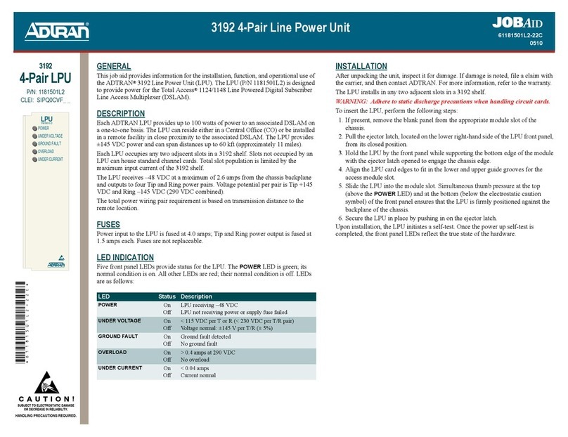
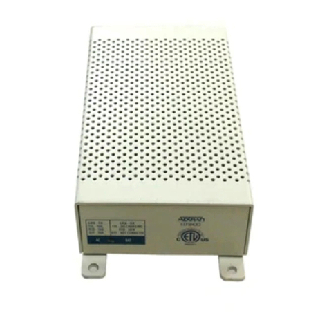
ADTRAN 3192 User manual

ADTRAN

ADTRAN 3192 User manual

ADTRAN 4303 DC Manual

ADTRAN

ADTRAN 4303 DC Manual

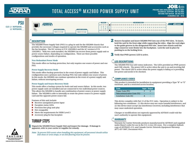
ADTRAN TOTAL ACCESS MX2800 User manual

ADTRAN

ADTRAN TOTAL ACCESS MX2800 User manual

ADTRAN Total Access 1500 Instruction Manual

ADTRAN

ADTRAN Total Access 1500 Instruction Manual

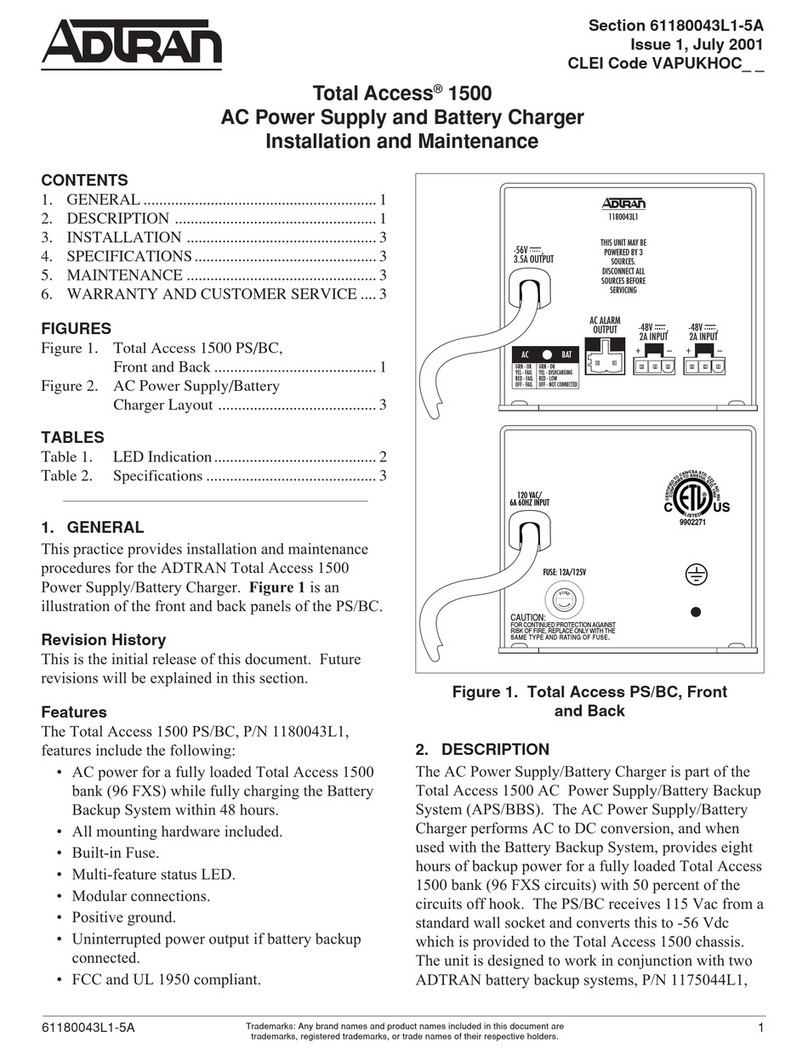
ADTRAN Power Supply/Battery Charger User manual

ADTRAN

ADTRAN Power Supply/Battery Charger User manual

ADTRAN ATLAS 890 User manual

ADTRAN

ADTRAN ATLAS 890 User manual

Popular Power Supply manuals by other brands

Diablotek UL Series user manual

Diablotek

Diablotek UL Series user manual

Kenwood PR-657 instruction manual

Kenwood

Kenwood PR-657 instruction manual

Vimar Eikon 20292 quick start guide

Vimar

Vimar Eikon 20292 quick start guide

Suaoki G500 user manual

Suaoki

Suaoki G500 user manual

Phoenix Contact FL MGUARD 1102 Installation notes

Phoenix Contact

Phoenix Contact FL MGUARD 1102 Installation notes

Pyramid PS-26KX instruction manual

Pyramid

Pyramid PS-26KX instruction manual

Sorensen DLM 5-75 Operation manual

Sorensen

Sorensen DLM 5-75 Operation manual

Kanlux BL-118H-EVG 1x18W manual

Kanlux

Kanlux BL-118H-EVG 1x18W manual

Basalte PUCK installation manual

Basalte

Basalte PUCK installation manual

Valcom VP-2124A Technical specifications

Valcom

Valcom VP-2124A Technical specifications

Philips Color Kinetics Power/Data Supply SPDS-60CA... product manual

Philips

Philips Color Kinetics Power/Data Supply SPDS-60CA... product manual

urmet domus 789 quick start guide

urmet domus

urmet domus 789 quick start guide

Altronix ALTV1224DC Series installation guide

Altronix

Altronix ALTV1224DC Series installation guide

TDK-Lambda FPS1000-12 instructions

TDK-Lambda

TDK-Lambda FPS1000-12 instructions

Siemens SITOP PSU100M operating instructions

Siemens

Siemens SITOP PSU100M operating instructions

Salicru DC POWER-S DC-36-S user manual

Salicru

Salicru DC POWER-S DC-36-S user manual

SLAT AES Series operating instructions

SLAT

SLAT AES Series operating instructions

Sentey BR POWER 500W user manual

Sentey

Sentey BR POWER 500W user manual

manuals.online logo
manuals.online logoBrands
  • About & Mission
  • Contact us
  • Privacy Policy
  • Terms and Conditions

Copyright 2025 Manuals.Online. All Rights Reserved.