Security Brands RIDGE RTE 14-RTE433 User manual

1 of 4
Model 14-RTE433
QUICK START GUIDE
2Make sure you have all items shown here. (Screwdriver not shown)
START HERE
1Carefully unpack box.
Key Switch
For enabling and
disabling unit
(Unit is disabled as
shown)
Exit Button
Triggers gate/door
to open
Lock
For securing interior
of RTE unit
RTE Unit Front Panel (Front) RTE Unit Front Panel (Back)
Internal wiring not shown for clarity.
Programming Button
For pairing transceiver
with RTE unit
Pairing Buttons
For pairing RTE unit
with transceiver
Status LED
Indicates
transmitting status
BTN 1
BTN 1
BTN 2
BTN 2
Power LED
Indicates whether or
not unit has power
Relay Status LED
Indicates whether relay is
active or inactive
(Relay is active when lit)
Connection Terminals
For wiring to compatible
AC/DC power source and
gate operator or door opener
Programming LED
Indicates status of
pairing process
CR2032 Battery
On underside of
circuit board
What’s what?
Important components labeled
Transceiver
Shown with cover removed.
Internal wiring not shown for clarity.
Lock Key Hole PlugCarriage Bolt
( 4x )
RTE Unit
(includes battery)
Key Switch Keys
(may look different)
Transceiver Unit Adhesive
Mounting Pad
Hex Nut
( 4x )
© 2021 Security Brands, Inc. All rights reserved.
2 of 4
Model 14-RTE433
QUICK START GUIDE
QSG-14RTE433-EN Rev. B (9/2021)
CAUTION!
The transceiver is not weatherproof and must be mounted inside a
weatherproof enclosure. Internal components can be damaged if
exposed to the elements.
Failure to comply will VOID WARRANTY.
WARNING!
AUTOMATIC GATES CAN CAUSE SERIOUS INJURY OR DEATH!
ALWAYS CHECK that the GATE PATH IS CLEAR BEFORE OPERATING!
REVERSING or other SAFETY DEVICES SHOULD ALWAYS BE USED!
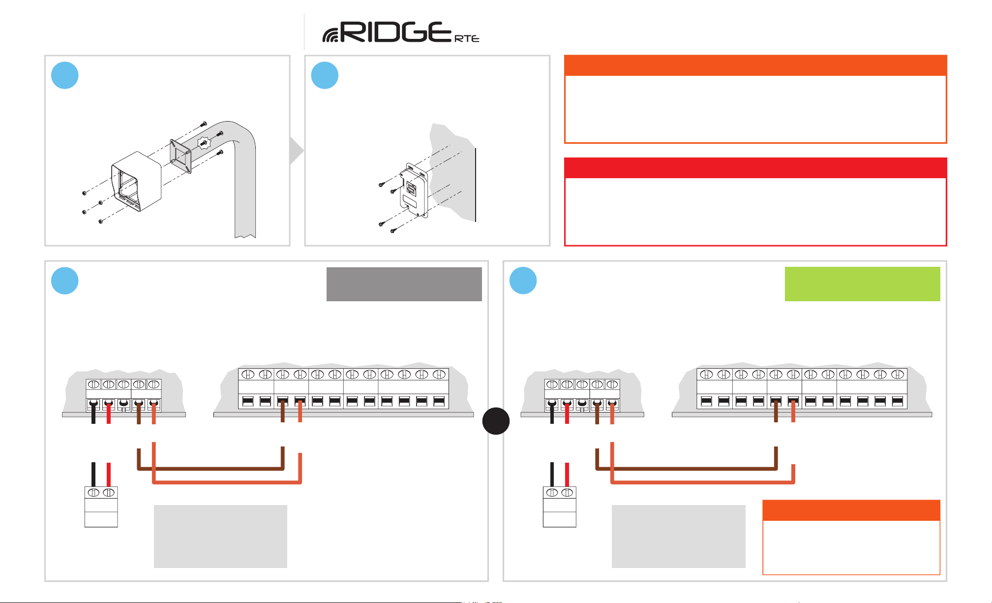
3Unlock and remove front panel of
RTE unit; then using included
carriage bolts and hex nuts, attach
unit to pedestal as shown.
4Using Tek screws, zip ties, or
included adhesive mounting pad,
attach transceiver to inside wall or
another surface of gate operator.
5a Connect transceiver
Ridge Transceiver
12–24 VAC/DC
POWER
RELAY
12–24 VAC/DC
POWER
Gate Operator / Door Opener
POS. (+)
NEG. (–)
COM
REVERSE LOOP
COM
OPEN
STOP
CLOSE
OR
12–24-VAC/DC
Power Source
(Not Included)
NC
NEG. (–)
POS. (+)
+–
COM
NO
FREE EXIT
COM
5b Connect transceiver
COM
RADIO
Ridge Transceiver
12–24 VAC/DC
POWER
RELAY
12–24 VAC/DC
POWER
Gate Operator / Door Opener
POS. (+)
NEG. (–)
COM
REVERSE LOOP
COM
OPEN
STOP
CLOSE
12–24-VAC/DC
Power Source
(Not Included)
NC
NEG. (–)
POS. (+)
COM
NO
FREE EXIT
COM
COM
RADIO
Gate Operator Timer-to-Close
OFF
Gate Operator Timer-to-Close
ON
A closing gate can cause injury to
persons or damage to property.
ALWAYS USE SAFETY DEVICES!
CAUTION!
Consult gate operator or
door opener manual for
exact connections.
Terminals vary widely across
manufacturers and models.
Consult gate operator or
door opener manual for
exact connections.
Terminals vary widely across
manufacturers and models.
+–

QUICK START GUIDE 3 of 4
Model 14-RTE433
BTransceiver Reset Procedure
This procedure is used to unpair all devices from the transceiver.
Step 1 - Remove screws and remove transceiver cover.
Step 2 - Press and hold Programming Button until Programming LED starts to flash.
Button must be held for about 30 seconds. Once flashing stops, all devices have been
unpaired from transceiver and reset is complete.
Step 3 - Replace transceiver cover and secure screws.
6d Relay on transceiver should click and
transceiver LED should go out. Pairing
is complete.
LED will
go out
BTN 1
BTN 1
BTN 2
BTN 2
6c Hold down both Pairing Buttons until Status LED
flashes. Let go of Button 2 and continue holding
Button 1 only until Status LED flashes again.
LED will light
solid red
6a Remove transceiver cover; then
hold down Programming button on
circuit board for 3 seconds and let go.
Your system is ready to use.
INSTALLATION COMPLETE!
N
7Make sure gate/door path is clear; then
press exit button on RTE unit and confirm
gate/door opens.
(If nothing happens, repeat Step 6)
Unit Enabled
(exit button active)
Unit Disabled
(exit button inactive)
AThe RTE unit can be disabled and re-enabled at any time by taking the
key switch keys and using the key switch located below the exit button.
6b Remove RTE unit front panel.
CHECK THAT THE GATE PATH IS CLEAR BEFORE
COMPLETING THIS STEP AS IT TRIGGERS THE RELAY!

© 2021 Security Brands, Inc. All rights reserved.
QUICK START GUIDE 4 of 4
Model 14-RTE433
QSG-14RTE433-EN Rev. B (9/2021)
NEED HELP Call (972) 474-6390
Email [email protected]
We are available Mon–Fri / 8am–5pm Central
Notes
Ridge RTE
14-RTE433
Other Security Brands Transceiver manuals


