Kenwood TS-60S User manual
Other Kenwood Transceiver manuals

Kenwood
Kenwood TH-75A User manual

Kenwood
Kenwood TK-840 User manual

Kenwood
Kenwood NX-5900 User manual

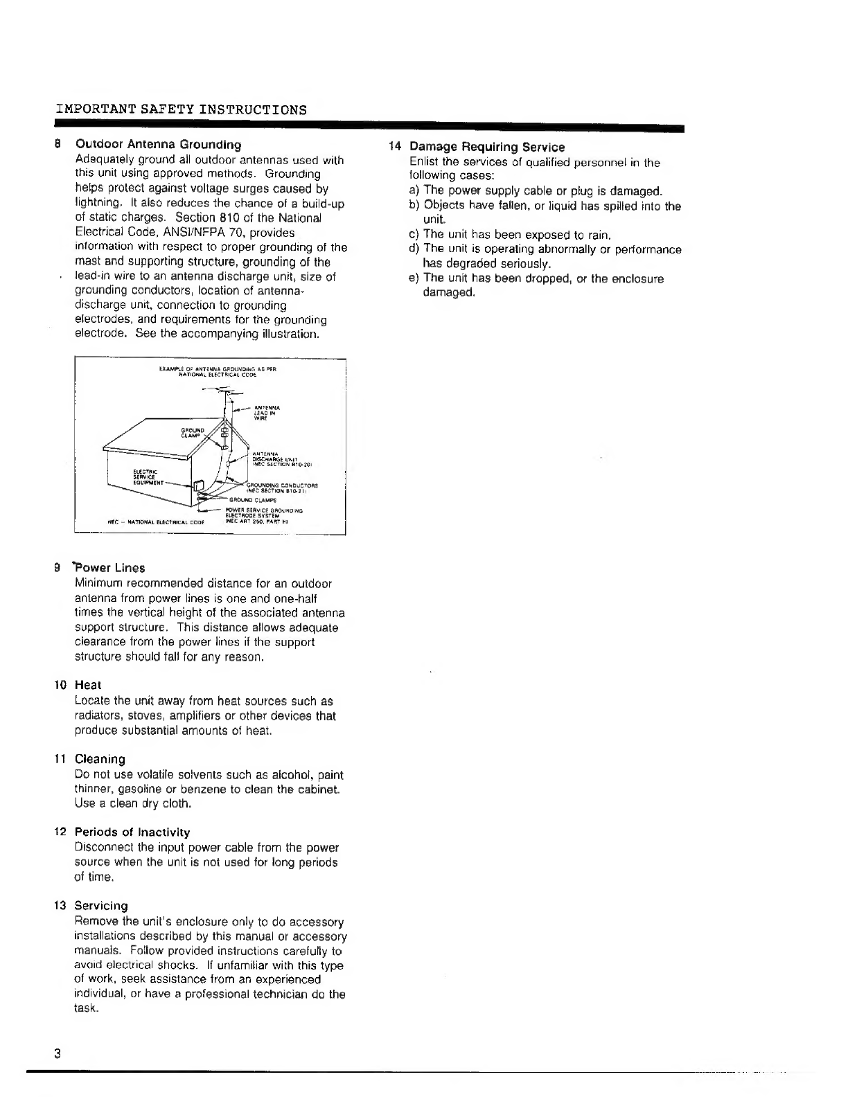
Kenwood
Kenwood TH-D7 A Operating instructions

Kenwood
Kenwood TH-D72A User manual

Kenwood
Kenwood TK-760G series User manual

Kenwood
Kenwood TS-770 User manual

Kenwood
Kenwood TS-711A/E User manual

Kenwood
Kenwood TK-D240 User manual

Kenwood
Kenwood TH-225A User manual
 User manual")
Kenwood
Kenwood M) User manual

Kenwood
Kenwood TR-7950 User manual

Kenwood
Kenwood TS-700 User manual

Kenwood
Kenwood FM Transceiver TK-481 User manual

Kenwood
Kenwood TS-450S User manual

Kenwood
Kenwood TH-F6A User manual

Kenwood
Kenwood TK-U100 User manual

Kenwood
Kenwood TH-79A User manual

Kenwood
Kenwood PKT-23LFP User manual

Kenwood
Kenwood TM-641A User manual