Icom IC-A110EURO User manual

iA110EURO
VHF AIR BAND TRANSCEIVER
INSTRUCTION MANUAL

i
FOREWORD
READ ALL INSTRUCTIONS carefully and completely
before using the transceiver.
SAVE THIS INSTRUCTION MANUAL —This in-
struction manual contains important operating instructions
for the IC-A110EURO.
EXPLICIT DEFINITIONS
The explicit definitions below apply to this instruction man-
ual.
CAUTIONS
RWARNING! NEVER operate the transceiver with a
headset or other audio accessories at high volume levels.
Hearing experts advise against continuous high volume op-
eration. If you experience a ringing in your ears, reduce the
volume level or discontinue use.
NEVER connect the transceiver to an AC outlet or to a
power source of more than 32 V DC. Such a connection will
damage the transceiver.
NEVER connect the transceiver to a power source that is
DC fused at more than 5 A. Accidental reverse connection
will be protected by this fuse, higher fuse values will not give
any protection against such accidents and the transceiver
will be ruined.
DO NOT operate the transceiver near unshielded electri-
cal blasting caps or in an explosive atmosphere.
DO NOT connect the transceiver to a power source using
reverse polarity. This connection will not only blow fuses but
also may damage the transceiver.
DO NOT place unit in a non-secure place to avoid inad-
vertent use by children.
WORD DEFINITION
RWARNING! Personal injury, fire hazard or electric shock
may occur.
CAUTION Equipment damage may occur.
NOTE If disregarded, inconvenience only. No risk
of personal injury, fire or electric shock.
Icom, Icom Inc. and Icom logo are registered trademarks of Icom In-
corporated (Japan) in Japan, the United States, the United King-
dom, Germany, France, Spain, Russia and/or other countries.

ii
DO NOT push [PTT] when not actually desiring to trans-
mit.
DO NOT use or place the transceiver in direct sunlight or
in areas with temperatures below –30°C (–22°F) or above
+60°C (+140°F).
DO NOT place the transceiver in excessively dusty envi-
ronments.
DO NOT place the transceiver against walls. This will ob-
struct heat dissipation.
DO NOT use harsh solvents such as benzine or alcohol
to clean the transceiver, as they can damage the transceiv-
er’s surfaces.
BE CAREFUL! The transceiver will become hot when
operating continuously for long periods of time.
TABLE OF CONTENTS
FOREWORD .......................................................................................... i
EXPLICIT DEFINITIONS ........................................................................ i
CAUTIONS ............................................................................................. i
TABLE OF CONTENTS .......................................................................... ii
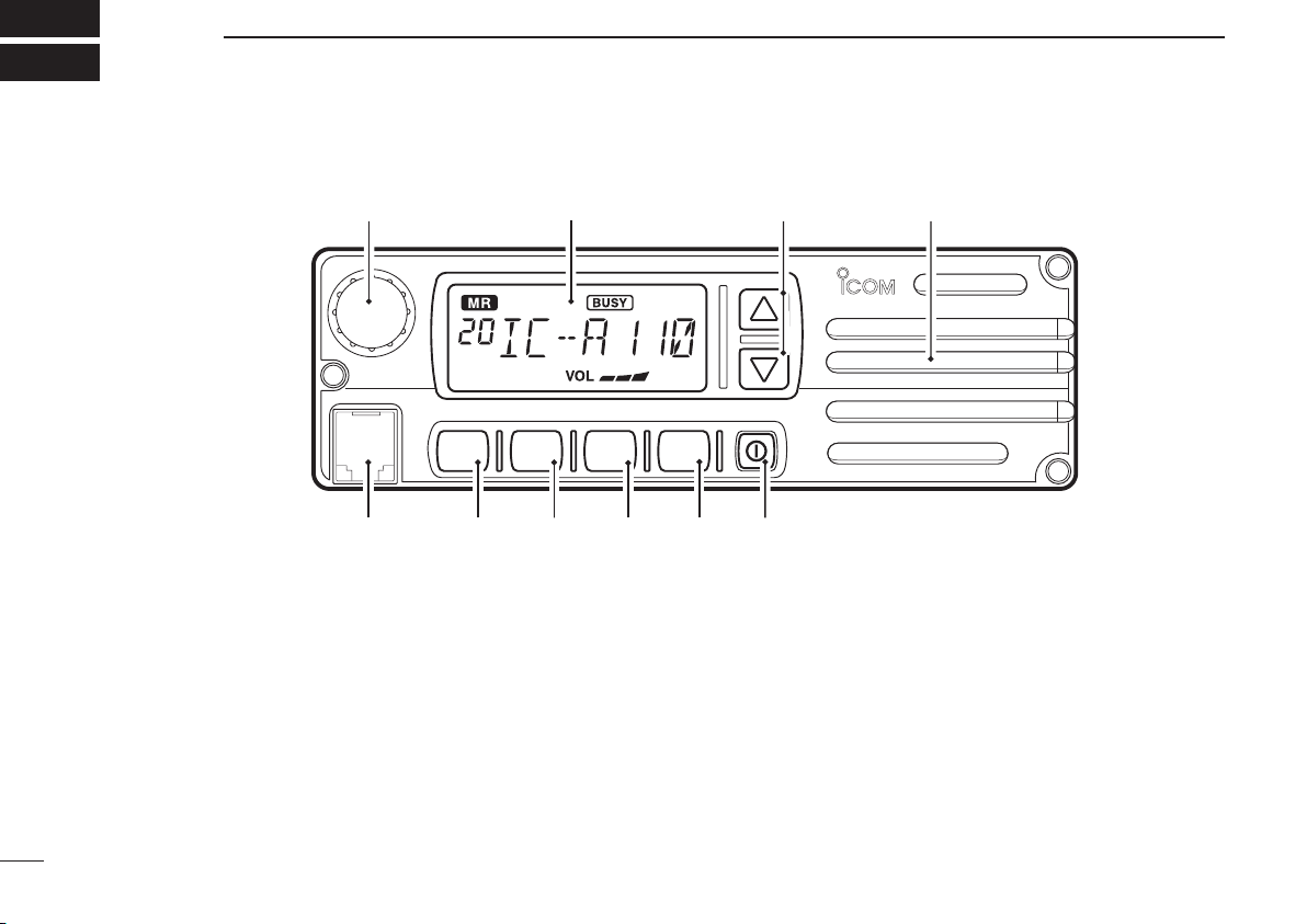
1 PANEL DESCRIPTION ............................................................. 1 – 3
■Panel description ................................................................................. 1
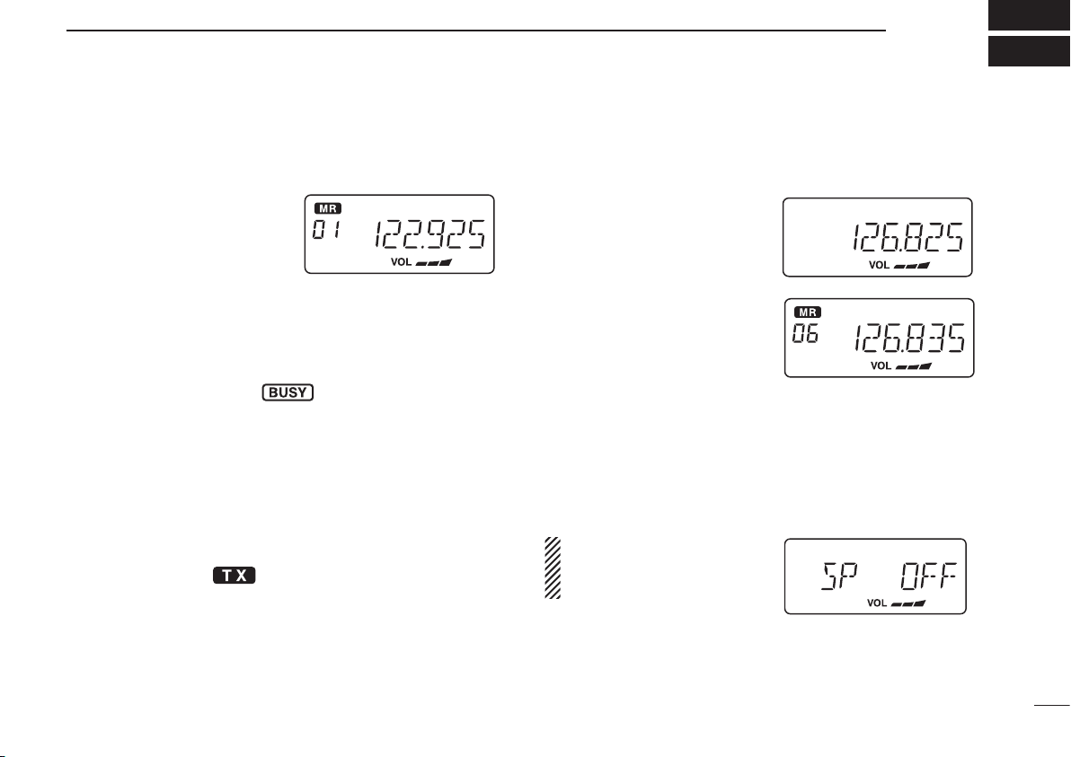
■Function display .................................................................................. 3
2 BASIC OPERATION ................................................................. 4 – 5
■Power ON ............................................................................................ 4
■Channel selection................................................................................. 4
■Squelch function................................................................................... 5
■Side tone function ................................................................................ 5
■LCD backlight control ........................................................................... 5
■Dial select function ............................................................................... 5
3 SCAN OPERATION .................................................................. 6 – 7
■Scan operation .................................................................................... 6
■ON-Hook scan ..................................................................................... 7
■Dualwatch ............................................................................................ 7
4 MEMORY PROGRAMMING ..................................................... 8 – 9
■Programming a memory channel ......................................................... 8
■Memory names .................................................................................... 9
5 OTHER FUNCTIONS ............................................................ 10 – 11
■Initial Set mode ................................................................................. 10
6 CONNECTION AND INSTALLATION ................................... 12 – 13
■Rear panel and connections ............................................................. 12
■Mounting ........................................................................................... 13
■Supplied accessories ......................................................................... 13
7 CLONING ...................................................................................... 14
8 SPECIFICATIONS .......................................................... 15 – 17
9 OPC-871 HEADSET ADAPTER/OTHER OPTIONS....... 18 – 19
■OPC-871 Headset adapter................................................................. 18
■Other Options..................................................................................... 19

■Panel description
qTUNING [DIAL] [TS](DIAL)
➥Changes the operating frequency; memory channel in
the Memory mode; set mode contents in the Set mode,
etc.
➥Push to toggle the dimmer control OFF, Low or High.
➥Hold down for 1 second to select the Tuning Step
[TS]; 1 MHz or 10 kHz are selectable. (p. 5)
wFUNCTION DISPLAY (p. 3)
Displays the operating frequency, memory channel name,
etc.
eVOLUME UP [Y] DOWN [Z]KEY
Adjusts the audio output level.
rLOUD SPEAKER
Front mounted loud speaker.
tPOWER SWITCH [POWER]
Hold down 0.5 seconds to turn the power ON and OFF.
•At Power ON, the Initial Set mode (p. 10) or the Cloning mode
(p. 14) can optionally be selected.
1
1PANEL DESCRIPTION
V/M
SCAN
PRI SQL
qw er
!0 oiuyt

2
1
PANEL DESCRIPTION
ySQL SWITCH [SQL]
➥Push to turn ON the squelch adjust mode. (p. 6)
➥Hold down this switch for 1 second to turn the both in-
ternal and external speaker output ON or OFF. (p. 4)
uPRIORITY SWITCH [PRI]
➥Push to select the priority channel. (p. 11)
•“Pr”appearsonthedisplay.
iSCAN SWITCH [SCAN]
➥Starts and stops the scan function:
•VFOmode:VFOscanfunction.(p.6)
•Memorymode:Memorychannelscanfunction.(p.6)
➥Hold down this switch for 5 seconds to set the dis-
played channel as a memory lock-out channel. (p. 8)
•“LOCKOUT”appearsonthedisplay.
oVFO/MEMORY SWITCH [V/M] [MW](V/M)
➥Push to toggle between the VFO mode and the Mem-
ory mode. (p. 4)
•“X”andmemorychannelnumberappearwhentheMem-
ory mode is selected.
•Thetransceiverhas99memorychannels.
➥When the VFO mode is selected;
• Hold down this switch for 5 seconds to enter the VFO fre-
quency into memory channel. (p. 8)
➥When the Memory mode is selected;
•Holddownthisswitchfor5secondstoturnONthe“Memory
namewritemode.”
!0 MICROPHONE CONNECTOR
Connects to the supplied microphone or optional.
NEVER connect other microphones. The pin assignments
may be different and the transceiver may be damaged.
MICROPHONE
The supplied microphone has a PTT switch and a cradle.
The following functions are available when the microphone
is taken off the hook or put back on the hook:
➥Automatic scan starts when the microphone is put ON Hook.
(p. 7)
➥Automatic scan stops when the microphone is taken OFF Hook.
(p. 7)
NOTE: Optional functions vary with transceiver version. In
this manual, optional functions are indicated by an
“ ” Icon.
Please contact your dealer for details.

3
1PANEL DESCRIPTION
■Function display
qMEMORY MODE INDICATOR (p. 5)
Appears when the Memory mode is selected.
wDUALWATCH INDICATOR (p. 7)
Appears when the dualwatch function is activated.
eSCAN INDICATOR (p. 8)
Appears when the scan function is selected.
rBUSY INDICATOR (p. 6)
“BUSY”appearswhenreceivingasignalorwhenthe
squelch is open. (p. 6)
tTX INDICATOR (p. 5)
Appears while transmitting.
yFREQUENCY DISPLAY (p. 11)
➥Shows the operating frequency.
➥Shows the channel name when the memory name
function is selected. (p. 10)
uVOLUME LEVEL INDICATORS
➥Shows the AF volume level (while receiving).
iSET MODE INDICATOR
➥Appears when the Initial Set mode is selected. (p. 12)
!0 LOCK OUT INDICATOR
➥Appears when the channel is set as a ‘LOCK OUT’
channel. (p. 10)
!1 MEMORY CHANNEL INDICATOR
➥Indicates the selected memory channel number
➥‘Pr’ appears when the priority channel is selected.
*NOTE: The VFO/memory switch [V/M] and the memory
write switch [MW](V/M) functions may not be available, de-
pending on version.
wqrt
!1
e
oiu
y

4
2
BASIC OPERATION
■Power ON
qPush [POWER] to turn ON the power.
wOperate the transceiver as described in the following sec-
tions.
eSelect the desired memory channel (or VFO frequency)
with the [V/M] keys.
•Whenreceivingasignal, appears and audio is heard
from the speaker.
•Furtheradjustmentoftheaudiolevelmaybenecessaryatthis
point.
•Push[SQL]toadjustthesquelchlevel.(p.6)
•Holddown[TS](DIAL)for1secondtoselectthetuningstep.
1MHz or 10 kHz are selectable. (p. 7)
rHold down [PTT] to transmit, then speak into the micro-
phone at your normal voice level.
•Transmitindicator lights.
tRelease [PTT] to receive.
■Channel selection
ï VFO/Memory selection
Push [V/M] to select the Mem-
ory mode or the VFO mode.
➥Rotate [DIAL] to select a de-
sired frequency or channel.
ï External speaker output control
External speaker output can be turned OFF, if desired.
qHolddown[SQL]for1second.
wRotate[DIAL]toselect“SPOFF”.
ePush[SQL]toreturntothepreviousmode.
NOTE: This function is avail-
able both internal and exter-
nal speakers.

5
2BASIC OPERATION
■Squelch function
The transceiver has a noise squelch circuit to mute unde-
sired noise while receiving no signals.
DSetting the squelch level
qPush[SQL]toturnONtheleveladjustingmode.
w Rotate [DIAL] to select the squelch level.
•‘SQ01’isloosesquelchand‘SQ25’istightsquelch.(In-
itiallevelis‘SQ01’)
•‘SQ01’indicatesthatthesquelchcircuitisturnedoff.
•“ ”appearsonthedisplay.
ePush[SQL]toreturntoregularoperation.
■Side tone function
When using an optional headset, such as those from the
David Clark Co. using the OPC-871 HEAD SET ADAPTER, the
transceiver outputs your transmitted voice to the headset for
monitoring. (p. 17)
■LCD backlight control
The backlight of the LCD can be set to OFF, Low or High.
➥Push [DIAL] to toggle the backlight control; OFF, Low or
High are selectable.
■Dial select function
Use the dial select function to adjust the tuning step of the
[DIAL] keys. Use 1 MHz tuning when you want to change the
frequency in large increments; use regular tuning (25 kHz or
8.33 kHz) when you want to change the frequency in
smaller increments.
qPush [V/M] to select the
VFO mode.
wHold down [TS](DIAL) for 1
second to select the desired
tuning increment.
•1 MHz tuning or regular
tuning steps can be se-
lected. (See the diagrams
to the right.)
eHold down [TS](DIAL) for 1
second to return to normal
operation.
NOTE: Large tuning steps should be used only when you
want to change the frequency in large increments. Please
select regular tuning steps for normal operation.
1 MHz tuning selected
Regular tuning selected

6
3
SCAN OPERATION
■Scan operation
qPush [V/M] to select the Memory mode or the VFO mode,
if necessary.
•“ ”appearswhenintheMemorymode.
wMake sure the squelch level is set to the threshold point.
•Setthesquelchlevel(01to25)wherethenoiseisjustmuted.
ePush [SCAN] to start the scan.
•Tochangethescandirection,turn[DIAL].
•“SCAN(orPSCAN)“asheswhilescanning.
rPush [SCAN] again to stop the scan.
NOTE: Normal scan or Priority scan is pre-programmed
by cloning. Please ask your dealer or system operator for
details.
ï NORMAL SCAN
•Memory lock scan
Repeatedly scans memory
channels except skip (lockout)
channels.
•VFO scan
Repeatedly scans all
frequencies over the entire
band. Scan step is minimum
channel spacing. (e.g. 25 kHz or
8.33 kHz)
ï PRIORITY SCAN
•Priority memory scan
While scanning in the Memory
mode, priority watch checks for
a signal on the selected
priority channel every 250
msec. and skips the lockout
channel(s).
Mch 2*
Mch 1
Mch 3
Mch 99
250 msec. *: Lockout ch
SKIP
Scan
Jump
Start highest
frequency
lowest
frequency
Priority
ch
Mch 2*
Mch 1
Mch 3
Mch 99
250 msec. 250 msec.
SKIP
*: Lockout ch

7
3SCAN OPERATION
■ON–Hook scan
An ON–Hook scan (Hanger scan) stops when taking the mi-
crophone off its hanger (OFF–Hook) and resumes when
putting it back on the hanger (ON–Hook).
➥Push [SCAN] to start scanning.
•Whenasignalisreceived,thescanpausesuntilthesignaldis-
appears.
•Thescanresumes2secondsafterthesignaldisappears,un-
less you pushed [PTT] and transmitted.
•Takethemicrophoneoffthehangertostopthescan.
•Putthemicrophonebackonthehangertoresumescan-
ning.
When you take the microphone OFF Hook during the scan
operation.
•InVFOscan;
the scan stops on the last frequency that was scanned.
•Inmemoryscan;
the scan stops on the last memory channel that was
scanned.
•Inprioritymemoryscan;
the scan stops on the priority channel.
NOTE: Be sure to connect the supplied microphone
hanger to the vehicle’s ground for ON and OFF Hook mi-
crophone functions. (p. 12)
■Dualwatch
Dualwatch monitors the priority channel while you are
receiving another channel (VFO or memory channel).
•Ifasignalisreceivedonthe
priority channel, dualwatch
pauses on the priority chan-
nel until the signal disap-
pears.
•Totransmitontheselected
channel during dualwatch,
hold down [PTT].
See page 11 for details of the priority channel setting.
ï Operation
qSelect the desired operating channel (VFO or Memory
channel).
wHold down [PRI] for 1 second to start dualwatch.
‘P’ blinks during dualwatch.
eTo cancel dualwatch, push [PRI] again.
VFO
frequency
or
memory
channel
Priority
channel
5 sec.
250 msec.

8
4
MEMORY PROGRAMMING
DSetting lockout channels
In order to speed up the scan periods, you can set memory
channels you don’t wish to be scanned as lockout channels.
qPush [V/M] to select the Memory mode, if necessary.
•“ ”appears.
wRotate [DIAL] to select a memory channel to set as a
lockout channel.
eHold down [SCAN] for 5 sec-
onds to toggle the lockout
setting ON or OFF.
•“LOCKOUT”appearswhen
the channel is set as a lockout
channel.
The transceiver has 99 memory channels for storage of
often-used frequencies.
qPush [V/M] to select the VFO
mode, if necessary.
wRotate [DIAL] to select the
desired frequency.
•Push[TS](DIAL)oneormore
times to use the dial select
function, if desired.
eHold down [MW](V/M) for 5
seconds to enter the mem-
ory programming mode.
•“ ”andthememorychan-
nel number appear.
rRotate [DIAL] to select the
desired memory channel
number.
tHold down [MW](V/M) for 1
second to program the infor-
mation into the channel and
return to the VFO mode.
•Tocancelthememoryinforma-
tion, hold dow n [ SQL] for 1
second.
MR
MR
MR
BUSY
SKIP
50
NOTE: The VFO/memory switch [V/M] and the memory
write switch [MW] functions may not be available, depend-
ing on version.
Memory channel 8 is set
as the lockout channel.
■Programming a memory channel

9
4MEMORYPROGRAMMING
■Memory names
ï Programming memory names
qSelect the memory channel to be programmed:
➥Push [V/M] to select the Memory mode.
➥Rotate [DIAL] to select the memory channel.
wHold down [MW](V/M) for 5 seconds to enter memory
name writing mode.
•Therstdigitblinks.
eRepeatedly rotates [DIAL] to select the desired character.
•Toeraseacharacter,overwritewithaspace(displayedas_).
•Tomovethecursorforwardsorbackwards,push[Y] or [Z].
•Holddown[SQL]for2secondstoeraseallcharacters.
rHold down [MW](V/M) for 2 seconds to input the entered
name.
•Thecharacterstopsblinking.
•Memorychannelscanbeprogrammedwithnamesofupto7
characters in length.
•Whennonameisprogrammed,thedisplayshowstheoperat-
ing frequency.
NOTE: Push [PTT] to cancel the memory name programming.
•Thefollowingcharacterscanbeusedinnames:
➥0 to 9,A to Z (capitals), (space), $,%,’,(,),✽,+,“
, ”,–,/,<,=,>,?,@,[,\,],^,_ and `.
V/M
for 5 sec.
V/M
for 1 sec.
+or
[EXAMPLE]:Settingthenameto“TOWER2”

5
OTHER FUNCTIONS
10
■Initial Set mode
The Initial Set mode is accessed at Power ON, and allows
you to set seldom-changed settings. In this way you can the
“customize”thetransceiveroperationstosuityour
preferences and operating style.
D Entering Initial Set mode
qWhile holding down [V/M] + [TS](DIAL), push [POWER] to
turn ON the power.
•ThetransceiverenterstheInitialSetmodeand“MN”,“BP”,“ST”
or“PR”(p.11)appearsonthedisplay.
wPush [TS](DIAL) to select the
desired item as described
below and to the right.
eRotate [DIAL] to select the de-
sired option or setting.
rPush [SCAN] to exit the Initial
Set mode and return to the
previous operating mode.
D Memory names
This item allows you to display a memory name instead of
the frequency.
•Whenamemorychannelhasnotbeenprogrammedwithaname,
the frequency appears instead.
D Beep tones ON/OFF
Conrmationbeeptonesnormally
sound when you push a key.
These can be turned ON or OFF,
as you prefer.
D Side tones ON/OFF
When using an optional headset
such as those from the David
Clark Co. using an adapter, the
transceiver outputs your transmit-
ted voice to the headset for moni-
toring.
• Optional OPC-871 HEADSET
ADAPTER is required.

OTHER FUNCTION
5
11
D Priority channel
The priority channel is used to store your most often-used
channel for quick recall. In addition, the priority channel is
monitored during priority scan modes. The default setting for
the priority channel will differ, depending on pre-program-
ming.
➥Push [PRI] to toggle the prior-
ity channel mode or previous
mode.
•Setting the priority channel
qWhile holding down [V/M] and [TS](DIAL), push [POWER]
to turn ON the power.
•Thetransceiverentersthe
Initial Set mode.
wPush [TS](DIAL) to select
the priority channel Set
mode.
eRotate [DIAL] to select the
desired channel number
as a priority channel or
OFF.
rHold down [POWER] to
turn OFF the power.
NEVER select the blank memory channel as the priority
channel. In such a case the priority function is automati-
cally set to the OFF position.

w
q
e
r
t
black: _
red: +
External speaker jack
OPC-871 HEADSET
ADAPTER (Option)
Antenna
Supplied DC
power cable
12 V or 24 V
Battery
6
CONNECTION AND INSTALLATION
12
■Rear panel and connections
qConnects to an antenna
Ask your dealer about antenna selection and best instal-
lation location. (Standard 50 Ωantenna with an SWR
<3.0)
wMICROPHONE HANGER
Connect the supplied microphone hanger to the vehicle’s
ground for to use the hanger scan function when hanging
or removing the microphone.
eDC POWER RECEPTACLE
Connects to a 12 or 24 V DC battery. Pay attention to po-
larities.
•12Vor24Vautomaticselectable.
rEXTERNAL SPEAKER JACK
Connect an 8 Ω, 30 W (Min.) external speaker, if desired.
CAUTION: DO NOT use an external speaker whose
power input rating is less than 30 W or whose imped-
ance is less than 8 Ω. Using a speaker of less than
30 W power rating, or less than 8 Ωimpedance, could
cause damage to the external speaker or to the trans-
ceiver itself.
tOPC-871 OPTIONAL HEADSET ADAPTER
Connect an optional headset. (See p. 17)

13
6CONNECTION AND INSTALLATION
■Mounting
The universal mounting bracket supplied with your trans-
ceiver allows overhead or dashboard mounting. Please read
the following instructions carefully.
•Mountthetransceiversecurelywiththe4supplied
screws (M5 ×20) to a surface which is more than 10
mm thick and can support more than 5 kg.
•Mountthetransceiversothatthefaceofthetransceiver
is at 90˚ to your line of sight when operating.
IMPORTANT!
Detailed installation notes for Icom mobile transceivers to
be fitted into vehicles are available. Contact your Icom
dealer or distributor.
■Supplied accessories
qMicrophone ................................................................................. 1
wMicrophone hanger and screw set........................................ 1 set
eMicrophone cable........................................................................ 1
rDC power cable (OPC-1091) ...................................................... 1
tMounting bracket......................................................................... 1
yBracket bolts ............................................................................... 4
uMounting screws (M5 × 12)......................................................... 4
iSelf-tapping screws (M5 ×20) .................................................... 4
oFlat washers................................................................................ 4
!0 Spring washers ........................................................................... 4
!1 Nuts............................................................................................. 4
!2 Fuses (10 A) ............................................................................... 2
qw
e
r
t
y
u
i
o!0 !1 !2
Flat washer
Spring washer
When using
self-tapping screws

14
7
CLONING
D Data cloning
Cloning allows you to quickly and easily
transfer the programmed contents from one transceiver to
another transceiver or data from a PC to a transceiver using
the optional CS-A110EURO cloning software.
D Transceiver to transceiver cloning
qConnect the OPC-591 CLONING CABLE with adapter plugs to
the [MIC] jack of the master and sub-transceivers.
•Themastertransceiverisusedtosenddatatothesub-transceiver.
wWhile holding down [Y] + [Z] + [V/M], push [POWER] to
enter cloning mode (master transceiver only—power ON
only for sub-transceiver).
•“CLONE”appearsandthe
transceivers enter the clone
standby mode.
ePush [POWER] on the master
transceiver.
•“CL-OUT”appearsinthe
master transceiver’s display.
•“CL-IN”appearsautomati-
cally in the sub-transceiver’s
display.
eWhencloningisnished,turn
power OFF, then ON again to
exit the cloning mode.
D Cloning using PC
Data can be cloned to and from a PC using the optional CS-
A110EURO CLONING SOFTWARE and the optional OPC-478 CLON-
ING CABLE+OPC-592 CLONING CABLE ADAPTER. Consult the CS-
A110EURO CLONING SOFTWARE HELP message for details.
D Cloning error
When the display to the right ap-
pears, a cloning error has oc-
curred.
•Inthiscase,bothtransceiversautomaticallyreturntothe
clone standby mode and cloning must be repeated.
]

15
SPECIFICATIONS
8
DGeneral
•Frequencycoverage :118.000to136.975MHz
•Channelspacing :25/8.33kHz
•Mode :AM(6K00A3E)
•No.ofmemorychannels :99
•Acceptablepowersupply :13.75V*or27.5V*DC
(negativeground) (*Automaticselection)
•Usabletemp.range :–20˚Cto+55˚C
•Frequencyerr :±1ppm(0to+40˚C)
•Currentdrain(at 13.75 V DC):
Tx 5 A (at max. power)
Rx 4 A ( at max. AF)
0.5 A (at stand by)
•Antennaimpedance :Standard50Ωwith SWR<3:1
•Dimensions :150 (W) ×50 (H) ×180 (D) mm
(projections not incl.)
•Weight(approx.) :1.5kg
DTransmitter
•Outputpower :9W±1.5dB(+15to+35˚C)
9 W +2 dB, –3 dB (–20 to +55˚C)
•Modulationdepth :Morethan85%
•Modulationcompression :Linear:85%,Max.:95%
•Amplitudemod.distortion :Lessthan10%
•Audiofrequencyresponse:+2dBto–4dBfrom
350 to 2500 Hz
More than –25 dB at 5000 Hz
(at 25 kHz channel spacing)
More than –25 dB at 3200 Hz
(at 8.33 kHz channel spacing)
•Adjacentchannelpower :Lessthan60dB
(at 25 kHz channel spacing)
Less than 50 dB
(at 8.33 kHz channel spacing)
•Conductedspuriousemissions:
Less than –46dBm
(9 kHz to 30 MHz)
Less than –36 dBm for
harmonics
Less than –46 dBm for non-
harmonics (30 MHz to 1 GHz)
Less than –30 dBm for
harmonics
Less than –40 dBm for non-
harmonics (1 GHz to 4 GHz)

16
8
SPECIFICATIONS (VFO CHANNEL ID LIST)
DReceiver
•Receivesystem :Doubleconversion
superheterodyne
•Intermediatefrequencies :1st 38.85MHz
2nd 450 kHz
•Sensitivity(at 12 dB SINAD) : Less than 5 dBµV
•Squelchsensitivity :Lessthan–6dBµV(Threshold)
•Harmonicdistortion :Lessthan5%(at30%mod.)
Lessthan10%(at90%mod.)
•Audiofrequencyresponse:+2dBto–4dBfrom
350 to 3000 Hz
(at 25 kHz channel spacing)
+2 dB to –4 dB from
350 to 2500 Hz
(at 8.33 kHz channel spacing)
•Audionoise :Morethan40dB
•Adjacentchannelrejection:Morethan60dB
•
Spurious response rejection
: More than 70 dB
•Intermodulationresponse:Morethan64dB
rejection
•Blockingordesensitisation:Morethan70dB
•Conductedspurious :Lessthan–57dBm
emissions (9 kHz to 1 GHz)
Less than –47 dBm
(1 GHz to 4 GHz)
•Crossmodulationrejection:Morethan70dB
•Receiverdynamicrange :Lessthan6dB
•Audiooutputpower :Morethan10W(at13.75V
DC with 8 Ωload60%MOD.
10%distortion)
Side tone More than 100 mW (with 500 Ω
load60%MOD.10%distor-
tion)
•Audiooutputimpedance :Ext.SP8 Ω
Side tone 500 Ω
All stated specifications are subject to change without
notice or obligation.

• Channel spacing: 8.33/ 25 kHz auto selection mode
17
8SPECIFICATIONS (VFO CHANNEL ID LIST)
Operating Freq. Channel spacing Channel ID
(MHz) (kHz) (Displayed Freq.)
118.0000 25 118.000
118.0000 8.33 118.005
118.0083 8.33 118.010
118.0167 8.33 118.015
118.0250 25 118.025
118.0250 8.33 118.030
118.0333 8.33 118.035
118.0417 8.33 118.040
118.0500 25 118.050
118.0500 8.33 118.055
118.0583 8.33 118.060
118.0667 8.33 118.065
118.0750 25 118.075
118.0750 8.33 118.080
118.0833 8.33 118.085
118.0917 8.33 118.090
118.1000 25 118.100
118.1000 8.33 118.105
• Channel spacing: 25 kHz (Actual frequency is displayed.)
• Channel spacing: 8.33 kHz
Operating Freq. Channel spacing Channel ID
(MHz) (kHz) (Displayed Freq.)
118.0000 8.33 118.005
118.0083 8.33 118.010
118.0167 8.33 118.015
118.0250 8.33 118.030
118.0333 8.33 118.035
118.0417 8.33 118.040
118.0500 8.33 118.055
118.0583 8.33 118.060
118.0667 8.33 118.065
118.0750 8.33 118.080
118.0833 8.33 118.085
118.0917 8.33 118.090
118.1000 8.33 118.105
These tables show just the display examples between
118.0000 MHz and 118.1000 MHz, not show all frequencies
in the band.
Operating Freq. Channel spacing Channel ID
(MHz) (kHz) (Displayed Freq.)
118.0000 25 118.000
118.0250 25 118.025
118.0500 25 118.050
118.0750 25 118.075
118.1000 25 118.100
Other manuals for IC-A110EURO
2
Table of contents
Other Icom Transceiver manuals
Popular Transceiver manuals by other brands

Thrane&Thrane
Thrane&Thrane Explorer 527 Getting started

KELVIN HUGHES
KELVIN HUGHES HBK-4002 quick start guide

Funkwerk
Funkwerk ATR833-LCD Operation and installation

Dell
Dell C-UBG-DEL4 installation manual

Delta Electronics
Delta Electronics Single Mode SFP Transceiver LCP-1250B4QDRx Specification sheet

evertz
evertz 7707GPS-DT manual