Securlift Secur3 User manual

X:\Ufficio Tecnico\DOCUMENTAZIONE\SECUR 3\Manuali\IM_SEC3_02.01_en.docx - 09/10/2017
Securlift sagl
Viale Serfontana 12
CH - 6834 Morbio Inferiore
Switzerland
INDEX
INTRODUCTION...................................................................................................................................................2
SYSTEM DESCRIPTION .........................................................................................................................................2
TECHNICAL SPECIFICATIONS................................................................................................................................3
TOPOGRAPHIC DRAWINGS .................................................................................................................................5
CABINETS ..........................................................................................................................................................13
INTERNAL LAYOUT ............................................................................................................................................19
PRELIMINARY TEST............................................................................................................................................20
INSULATION TEST..............................................................................................................................................21
DZSM - DOOR ZONE SAFETY MODULE TEST.......................................................................................................22
RUN TIME SUPERVISION TEST ...........................................................................................................................23
OVERSPEED GOVERNOR REMOTE TEST. ............................................................................................................23
FINAL LIMIT SWITCHES TEST..............................................................................................................................24
EN 81-20 –A3 AMENDEMENT (EN 81-1 & EN 81-2) ...........................................................................................25
ELGO LIMAX –ABSOLUTE POSITIONING SYSTEM ..............................................................................................29
SEC-3Q –CONTROLLER MOTHER BOARD ..........................................................................................................31
SEC-3AUX –BOARD WITH AUXILIARY RELAY.....................................................................................................35
SEC-3KBD –USER INTERFACE KEYPAD...............................................................................................................37
SEC-3S –SAFETY CIRCUIT BOARD REV. 2.0 ........................................................................................................40
SEC-3C –CAR BOARD ........................................................................................................................................43
SEC-3TRG –COP BOARD....................................................................................................................................46
SEC-3I/O –EXTENSION BOARD..........................................................................................................................48
SEC-2L –FLOOR NODE BOARD...........................................................................................................................50
SEC-2LPI –LANDING DISPLAY BOARD................................................................................................................54
SEC-2FDR –ALARM BATTERY CHARGER ............................................................................................................55
MANUAL RESCUE OPERATION INSTRUCTION....................................................................................................57
HELPY L300 –TELEPHONE DIALLER....................................................................................................................59
LEGENDA...........................................................................................................................................................60
SOFTWARE DOWNLOADING .............................................................................................................................66
SOFTWARE UPDATING BY USB MEMORY STICK ................................................................................................69
V3F SPEED SELECTION .......................................................................................................................................70

follows: IM_SEC3_02.01_en.docx
2/70
Introduction
The SECUR 3 modular system allowed our designers to develop innovative and reliable microprocessor
based controllers.
This system assigns to peripheral co-processors the activation of related inputs and outputs. In this
application every node of the system is connected by a simple two-wire connection.
The serial communication system which is used between boards in car and in control panel is based on
CAN (CONTROLLER AREA NETWORK). The protocol follows the ISO-IS 11898 rules for high speed
transmission (over 125 Kbit/sec), and the ISO-IS 11519-2 for low speed transmission (up to 125 kbit/sec).
The CAN network layout is a multi-master. In other words the unit that needs to send an information takes
possess of the bus and send its message, which is received and decoded by the receiving units. If more
units need contemporarily the bus for transmission, automatically the highest priority will be assigned.
If one of the verification gives a negative result the message will be repeated.
This is SECUR 3, a technologically advanced system.
System description
The SECUR 3 system is composed by the combination of the following electronic boards:
•SEC-3Q: controller mother board. It is the base of the system, and holds:
•SEC-3AUX: board with auxiliary relay
•SEC-3IO: additional inputs and outputs board (calls, etc.)
•SEC-3S: the safety circuit supervision board
•SEC-3C: car roof board. It handles the communication between car and controller, and holds:
•SEC-3I/O: additional inputs and outputs board (calls, etc.)
•SEC-3TRG: is the COP board; collects all car commands and signalisations and transmit them to SEC-
3C board; it may be located both inside COP or in the connection box on car roof
•SEC-2L: the landing node board. It handles the landing calls and signalisation, in serial mode, and holds:
•SEC-2LPI: the driver for position indicators at landing (in serial mode only)
•SEC-2FDR: the alarm battery charger and alarm handling.

follows: IM_SEC3_02.01_en.docx
3/70
Technical specifications
BASIC SPECIFICATION
•Modular system up to 32 floors (64 services).
•microprocessor
•CAN (Controller Area Network) serial transmission from controller to:
•Car, landings, inverter
Interfaces
•Removable user interface for parameter setting and controller diagnostic:
•SECUR 3 system parameters
programming
•special functionalities (rescue drive, door
commands, calls, etc.)
•fault codes and diagnostic visualisation
•date/time setting
•inverter programming and diagniostic
•USB port for SW update and parameters backup
•Serial port for local or remote monitoring
Drives
Hydraulic lift:
•Power units: all
•direct starting, star/delta starting, soft
starter
Traction lift:
•Asynchronous motors
•Gearless Synchronous motors
•AC 1 / 2 speed
•V3F open loop
•V3F closed loop
Logic
•Push button
•Down collective, Up collective, Full collective
•Multiplex (up to 4 lift group)
Doors
•automatic, semi-automatic, swing doors
•single, double access
•contemporary or selective door opening
•parking either with opened or closed doors
•door operators type: all
Emergency devices
•manual lowering emergency feature
(standard on MRL Gearless installation)
•automatic emergency device for lowering
and doors opening
•auto-dialer
•SMS automatic transmission in case of alarms

follows: IM_SEC3_02.01_en.docx
4/70
Signalisation
•24 VDC –1W per output
•Gong / voice announcer in 4 languages (standard) –other languages upon request
•car position indication: 1 wire per floor, 7 segment, dot matrix, LCD binary
•Other signalisation:
•car busy/coming
•car here
•car call registered
•landing call registered
•car direction
•hall lanterns - gong
•overload
•out of service
•fire recall/fireman’s drive
Protections
All SECUR 3 input/outputs are protected against:
•over-voltage (up to 125 VDC) •over current –short circuit
•electro-magnetic interferences (according to
EN standards)
•motor temperature protection: thermistors
or thermal relay
•lack/reverse phase
•max. run time
ELECTRICAL SPECIFICATIONS
Mains supply:
•standard: 220V, 230V, 380V, 400V –3 phase - 50 Hz.
•optional: monophase 220V, 230V, 240V,
3 phase 208V, 415V –50/60Hz.
Brake supply:
•standard: 200 VDC •optional: any other voltage
Valves supply:
•standard: 48 VDC •optional: all
Safety circuit with optoisolators:
•standard: 230 VAC –48VDC •optional: 110VAC
Shaft positioning system
•bistable - monostable magnetic switches •absolute encoder by magnetic band
Options
•overload and full load function
•short floor functions
•car / landing priority
•car light –fan timer
•fire recall
•advance door opening
•fireman’s drive
•floor access by code or iButton
•out of service
•remote monitoring
Norms
•EN 81-1; EN 81-2
•A3 amendment
•EN 81-20; EN 81-50
•EN 81-21
•EN 81-70
•95/16/CE
•Legge 13 –DM 236
•EN 81-72
•EN 81-73
•EN 81-80
•CE marking - 2014/33/UE directive
•EN 50081-1 electromagnetic emissions
•EN 50082-2 electromagnetic immunity

follows: IM_SEC3_02.01_en.docx
5/70
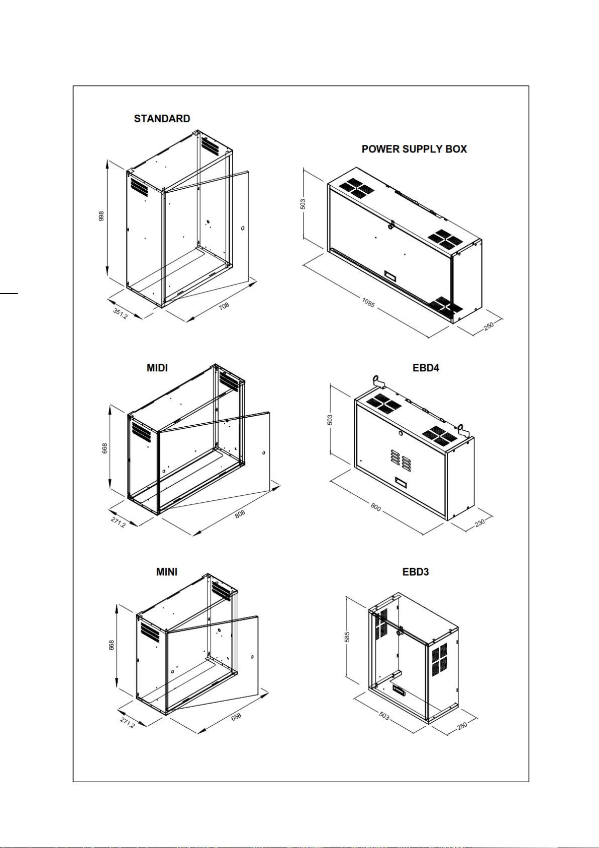
Topographic drawings

follows: IM_SEC3_02.01_en.docx
6/70

follows: IM_SEC3_02.01_en.docx
7/70

follows: IM_SEC3_02.01_en.docx
8/70

follows: IM_SEC3_02.01_en.docx
9/70

follows: IM_SEC3_02.01_en.docx
10/70

follows: IM_SEC3_02.01_en.docx
11/70

follows: IM_SEC3_02.01_en.docx
12/70
follows: IM_SEC3_02.01_en.docx
13/70
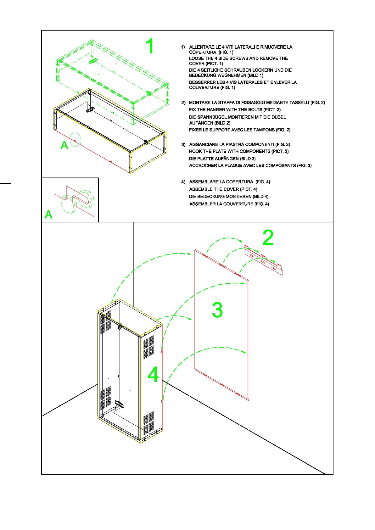
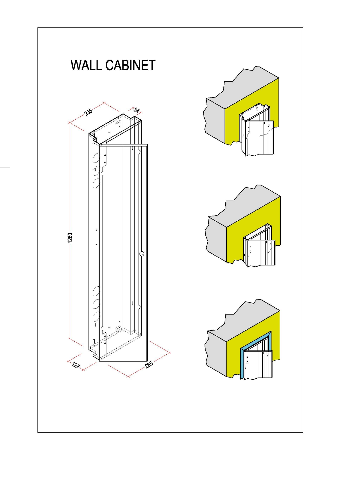
Cabinets
follows: IM_SEC3_02.01_en.docx
14/70

follows: IM_SEC3_02.01_en.docx
15/70

follows: IM_SEC3_02.01_en.docx
16/70
follows: IM_SEC3_02.01_en.docx
17/70

follows: IM_SEC3_02.01_en.docx
18/70

follows: IM_SEC3_02.01_en.docx
19/70
Internal layout
Control panelovra
Car roof connection box

follows: IM_SEC3_02.01_en.docx
20/70
Preliminary test
In order to perform preliminary test a TEMPORARY command box has to be connected to controller,
strictly following the below diagram.
! DO NOT USE THE PRE-WIRED INSPECTION BOX DELIVERED WITH THE CONTROLLER !
Do not install the car roof box (board SEC-3C)
Referring to installation electric drawings, connect following circuits:
a) Mains supply - terminals M1,M2,M3 (ref. page 1)
b) Motor supply –terminals M4,M5,M6 (U,V,W –ref. page 1)
c) Brake supply (if traction lift) –terminals 50 e 51 (ref. page 4), or BR+ e BR- (ref. page 22)
d) Valves supply (if hydraulic lift) –(ref. page 4)
e) temporary command box, by a suitable travelling cable
ATTENTION: do not use the pre-wired inspection box
f) motor thermal protection (ref. page 1)
g) all the ground/earth connections to all devices
h) bridge out connection related to non-existing devices (ref. page 3)
i) remove wire between P1/1 –P1/4 on controller board (SEC-3Q)
Following verifications has to be performed:
j) check all supply voltages
k) check that controller display shows RECALL
l) check that safety circuit led’s on board SEC-3S (SUPPLY, SHAFT, CAR , SWING DOORS, CAR DOORS,
LOCKS) are lit while pressing RUN and UP or DOWN buttons on the command box.
ATTENTION
After the preliminary test is finished, restore all connection to the original condition,
carefully checking the safety circuit.
Table of contents
Popular Measuring Instrument manuals by other brands


PCB Piezotronics
PCB Piezotronics ICP 353B77 Installation and operating manual

Dickey-John
Dickey-John GAC 2500-AGRI Operator's manual

Mcube
Mcube MC3419 Quick Start Guide and Demo

ROOTECH
ROOTECH Accura 2350-GW Quick setup guide

GHM
GHM Greisinger G 1409 operating manual

Aethlabs
Aethlabs microAeth MA Series quick start guide


