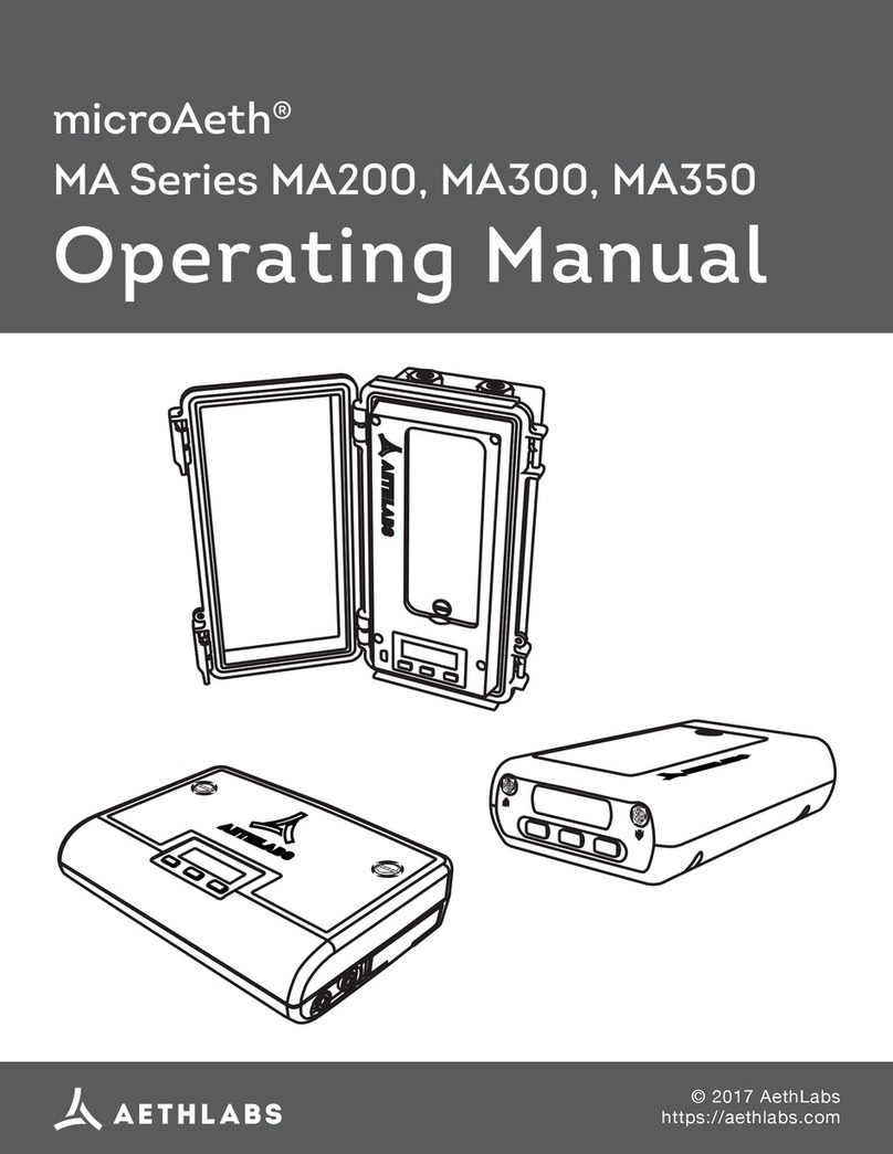
Aethlabs microAeth MA Series User manual

microAeth®MA Series MA200, MA300, MA350 Quick Start Guide AethLabs
1
microAeth®
MA Series MA200, MA300, MA350
Quick Start Guide
© 2024 AethLabs
https://aethlabs.com
FW v1.13.1, mAM v1.6.0.208, Feb 2024, rev01

microAeth®MA Series MA200, MA300, MA350 Quick Start Guide AethLabs microAeth®MA Series MA200, MA300, MA350 Quick Start Guide AethLabs
2 3
Introduction
Thank you for your purchase of an AethLabs microAeth® MA Series Black Carbon
monitor. This guide is a short introduction to setting up and using your microAeth
instrument. Please refer to the MA Series Manual for more detailed information.
Carefully unpack the instrument and accessories from their packaging. Check to identify
that all items are present and that there is no damage. Retain original packaging for safe
storage and shipping of the instrument.
The small size and light weight of the microAeth MA series instruments will allow you
to gather data in a wide range of mobile or stationary applications. The MA series lter
cartridge enables unattended operation from multiple weeks to a year, depending on
the model, settings, and environmental factors. Optimization of performance across this
breadth of applications requires an understanding of operational settings, precautions, and
maintenance procedures. The following recommendations provide general guidelines.
Charging the microAeth
Before using the instrument, the internal battery can be charged by plugging it in to
external power using the barrel jack power adapter. Battery runtime varies with settings
and age of the pump and battery.
The on-board screen displays a lightning bolt to the left of the battery indicator in the top
right corner, when the instrument is turned on, connected to an external power source
using the 5V barrel jack port.
lightning bolt
charging symbol
Charging times with instrument turned o:
MA200: DC via barrel jack AC adapter: ~3 hours
MA300: DC via barrel jack AC adapter: ~11.75 hours
MA350: Sealed connector DC via barrel jack AC adapter: ~11.75 hours
Table of Contents
Introduction 3
Charging the microAeth 3
Important information Before Getting Started 4
Installation & Environmental Considerations 5
Recommendations and Best Use Practices 7
MA200 Included Items 8
MA300 Included Items 10
MA350 Included Items 12
Operation 14
Turn On:
Turn O:
On-board Status Indications:
Menu Options:
During Startup:
During Sampling:
Operating Parameters:
Filter Tape Cartridge Removal and Installation 17
To remove lter tape cartridge:
To install lter tape cartridge:
Performing Measurements 20
To Start Sampling and Measrements:
To Stop Sampling and Measrements:
USB Communication, Conguration, & Data Export 21
To connect and congure the microAeth using the microAeth Manager application:
To download data to the microAeth Manager local database:
To export downloaded data from microAeth Manager to data les on computer:
To delete all data on the microAeth:
Calibration 24
Cleaning & Maintenance 25
Status Codes 25

microAeth®MA Series MA200, MA300, MA350 Quick Start Guide AethLabs microAeth®MA Series MA200, MA300, MA350 Quick Start Guide AethLabs
4 5
10) To get the best data from the microAeth MA Series instruments, we highly
recommend that the instrument warm up for approximately 30 minutes so that it can
equilibrate.
11) If you change sampling settings or download data (non-streaming data), you must
stop the instrument measurement before being allowed to make a change. Every time
the measurement starts into the sampling mode, the lter tape cartridge automatically
advances to a clean spot. Stopping and starting the instrument will therefore consume
more tape than just sampling without stopping the measurement intermittently.
Installation & Environmental Considerations
The microAeth instrument is specically designed to be used in a wide range of
measurement scenarios. Each research deployment will require its own specic
considerations for protecting the instrument and ensuring the integrity of your data. The
included sample tubing assembly with threaded insert should be installed into the inlet of
the instrument. Obstruction of either the inlet or outlet port should be prevented as this
will aect the ow of air into the instrument.
In personal monitoring applications, the included lapel clip can assist in positioning the
sampling inlet near to the person’s breathing zone, care must be taken to ensure the inlet,
or microCyclone inlet, are free from obstruction.
For outdoor deployments, protection of the instrument and the inlet and outlet ports
must be considered. An Inlet Protection Kit (WPK-20-25) should be used to help protect
the instrument and data from moderate water and bug intrusion and in-line condensation
through the sampling train.
Outdoor installation of MA series requires protection from rapid temperature changes and
moisture / precipitation. In addition to potentially having signal-to-noise implications on
your data, rapidly changing environmental conditions can harm your instrument without
proper protection. It is possible that an environmentally controlled enclosure could be
helpful and/or necessary. The instrument should be shielded from solar radiation to
reduce impact of rapid heating from the sun.
The MA350 features more robust weather protection, though it is not completely
weatherproof. While the case itself is rated IP67, necessary penetrations in the enclosure
Important information Before Getting Started
1) The microAeth Manager application for MacOS and Windows can be used to modify
all instrument settings but only some settings can be modied using the on-board user
interface on the front panel of the microAeth instrument.
2) Timebase:
The microAeth MA instruments can acquire data on timebase settings of 1, 5, 10, 30, 60,
or 300 seconds. The 1, 5 and 10 second timebases should only be used under special
circumstances where a decreased signal-to-noise ratio is acceptable. At this setting,
instrumental noise is larger and typically requires the highest ow rate and/or post-
processing. For stationary outdoor applications, we recommend longer timebases such as
the 300 second setting.
3) Flow Rate:
The MA series pump can operate at ow rate settings of 50, 75, 100, 125, 150 or 170 ml/
min. A higher ow rate can contribute to greater measurement sensitivity but will use more
lter tape and more power.
4) The lowest wavelength light source enabled will typically trigger the attenuation
(ATN) tape advance threshold. For example if 5 wavelengths are enabled, the UV channel
should always trigger the tape advance.
5) Measurement Wavelengths: What are you trying to measure? What wavelengths are
important for your measurements? More is not always better. Operating with the IR
channel only will increase tape life by at least 2.3x.
6) Tape advance ATN threshold: If DualSpot® is enabled, a higher ATN threshold can be
used as DualSpot will help correct for aerosol composition dependent loading eects.
7) DualSpot® vs SingleSpot™: A ow rate of 100 ml/min or greater is highly
recommended when using DualSpot® loading compensation. Using DualSpot® will
allow measurements at higher ATN loadings (longer sampling at each lter tape sampling
location) as the data are compensated in the BCc data column.
NOTE: Due to the ow split between Spot 1 and Spot 2 the measurement sensitivity in
DualSpot® mode will be lower than in SingleSpot™ mode for the same total ow rate that
is selected. When the DualSpot calculation and compensation is active (when ATN for
BC1 >= 3) the data will have more noise, this is expected behavior. Simple smoothing can
be applied to reduce the noise, or the smoothed columns in the data le can be used if
helpful.
8) Protect the instrument and the inlet and outlet ports from water and other
contaminates. Aethlabs can provide an inlet protection kit with a water/bug trap with rain
protection at the inlet.
9) Verify ow rates using on-board test ow menu and external ow calibration kit before
calibrating ows. The instruments are initially calibrated at sea level. Only calibrate the ow
system if there is an error in the measured ow when using the test ow menu. if sampling
is being done at a high elevation compared to sea level then a calibration may be required
to compensate for the change in altitude.

microAeth®MA Series MA200, MA300, MA350 Quick Start Guide AethLabs microAeth®MA Series MA200, MA300, MA350 Quick Start Guide AethLabs
6 7
for the inlet and outlet are obviously open to the elements. Our inlet and outlet ports are
protected by custom made ttings with dual o-ring seals for backup protection. As long as
the inlet and outlet sample lines are installed in a protected way as described earlier, then
the device is robust and protected from the elements. For continuous monitoring outdoors
we still recommend the instrument be further protected from the sun and precipitation. The
MA350 comes with included mounting hardware for wall mounting. AethLabs also oers a
pole mounting kit.
Temperature:
microAeth instruments are specied to operate between 5 ~ 40 °C. Furthermore, rapid
changes in temperature can impact data. Such eects are inversely propertional to
timebase and ow rate settings. It is possible that an environmentally controlled enclosure
could be helpful and/or necessary depending on the application.
Humidity:
As with many other types of particle measurement instrumentation, changes in relative
humidity can change the size and optical properties of particles. For locations with high
RH variability, an external sample dryer or heater may be used to condition the sample.
AethLabs oers a portable aerosol dryer for this application. Moving between a dry, air
conditioned environment, to a high humidity environment can impact the data while the
device equilibrates. Selecting a higher owrate and longer timebase will help to reduce
these eects.
Contamination:
Preventative maintenance for your deployment and sampling apparatus are important
for protecting your instrument. Keeping the microAeth and its air passageways, internal
components, and optical chambers clean is critical for maintaining the instrument and
producing quality measurements. <bold> We recommend, at a minimum, Standard
Maintenance Service at AethLabs or an authorized service center on at least an annual
basis.
Typically, Black Carbon particles are smaller than one micron in diameter. In some
sampling conditions where the aerosol is primarily composed of light scattering particulate
matter, such as dust or smoke from biomass fuels, there can be a prevalent fraction
of larger-diameter particles. Contamination of the instrument can cause increased
measurement noise, poor sealing of the analytical area and degraded operational lifetime
of some components.
For these applications, and to add contamination protection for your microAeth in high
concentrations, AethLabs oers a microCyclone™ size selective inlet that will limit the size
of the particles entering the microAeth to less than 2.5 microns in diameter when used
at at the specied ow rate. The microCyclone may not be appropriate for use with the
microAeth MA200, MA300, or MA350 in some applications depending on required ow
rates for DualSpot® loading compensation or other application specic ow requirements.
Contact AethLabs for more information.
Recommendations and Best Use Practices
Instrument Settings: We recommend getting started using the 60 seconds timebase and
100mlpm ow rate settings, with 5 wavelengths enabled. After using the instrument in your
application and collecting some data, these settings can be easily changed depending on
your requirements.
SingleSpot™ vs DualSpot®: DualSpot® loading compensation method corrects for the
optical loading eect and provides additional information about aerosol optical properties.
This method simultaneously collects aerosol samples on two analysis spots in parallel and
at dierent face velocities while measuring the rate of change in absorption of transmitted
light due to the particles loading on the lter. The use of this method is an optional user
selectable feature in the microAeth Manager program. DualSpot is usually recommended,
though SingleSpot with a lowered ATN threshold of 50 (with UV enabled) usually has
minimal loading eect in the IR channel
The timebase, ow rate, and WiFi settings will have the greatest impact on battery run
time. NOTE: Battery life will start to gradually diminish after many cycles (~ 1 year of use).
Runtimes can vary based on individual MA series instruments.
Individual Data Point Noise:
Instrumental noise contributes a random perturbation to the ‘ideal’ BC data. Its magnitude
is inversely proportional to the operational parameters of timebase and ow rate. Data
collected on a 1 second timebase should always be smoothed or averaged over longer
periods, unless measuring high concentrations where the instrumental noise is negligible.
Eects of Contamination, Vibration, and Impact: Primarily aected by timebase setting.
Increased ow rate will also reduce the eect.
1 second 5 seconds 10 seconds 30 seconds 60 seconds 300 seconds
very large large large moderate low least
Choosing the Tape Advance ATN for your application:
Choosing the right tape advance ATN trigger helps ensure the integrity of your
measurement by reducing possible loading eects. Loading eects are variable, aerosol
dependent, and are not always present. The range of the Tape Advance ATN trigger
is 1 to 100. The lower the Tape Advance ATN trigger setting, the lower the impact of
loading eects on the data at the expense of more tape consumption. Your settings from
SingleSpot™ vs DualSpot®, Flow Rate, and Wavelengths also impact how frequently you
reach your ATN setpoint and tape advance frequency.

microAeth®MA Series MA200, MA300, MA350 Quick Start Guide AethLabs microAeth®MA Series MA200, MA300, MA350 Quick Start Guide AethLabs
8 9
MA200 Included Items
microAeth MA200 Instrument Diagram
1. Inlet port
2. User interface screen
3. Outlet port
4. User interface buttons (3)
5. DC Barrel jack port
6. USB mini-B port
7. 4-pin 3.3V TTL serial port
8. Filter tape cartridge door
9. Flat head screw in lter tape cartridge door
10. Serial number label
Quantity Part Number Description
1 MA200 microAeth MA200
1 MAFT-L17
MA200 Filter Tape Cartridge,
17 Sampling locations
(installed in instrument)
1 AC-XP12B-5020 Barrel jack AC adapter with 1
territory-specic plug
1 USB-C-MX-0100 mini USB communication cable
1 MASH-40
Sampling Hose with Barb Fitting
Swivel Connector,
40 inches (1 meter)
1 MALC Lapel clip for sampling hose
Download Cross-platform microAeth® Manager software
(download via AethLabs website)
Download Quick Start Guide (download via AethLabs website)
Download Manual (download via AethLabs website)

microAeth®MA Series MA200, MA300, MA350 Quick Start Guide AethLabs microAeth®MA Series MA200, MA300, MA350 Quick Start Guide AethLabs
10 11
MA300 Included Items
microAeth MA300 Instrument Diagram
1. Filter tape cartridge door
2. Flat head screws (2) in lter tape cartridge door
3. User interface screen
4. User interface buttons (3)
5. Inlet port
6. Outlet port
7. DC Barrel jack port
8. USB mini-B port
9. 4-pin 3.3V TTL serial port
10. Serial number label
Quantity Part Number Description
1 MA300 microAeth MA300
1 MAFT-L85
MA300/350 Filter Tape Cartridge,
85 Sampling locations
(installed in instrument)
1 AC-XP12B-5020 Barrel jack AC adapter with 1
territory-specic plug
1 USB-C-MX-0100 mini USB communication cable
1 MASH-40
Sampling Hose with Barb Fitting
Swivel Connector,
40 inches (1 meter)
1 MALC Lapel clip for sampling hose
Download Cross-platform microAeth® Manager software
(download via AethLabs website)
Download Quick Start Guide (download via AethLabs website)
Download Manual (download via AethLabs website)

microAeth®MA Series MA200, MA300, MA350 Quick Start Guide AethLabs microAeth®MA Series MA200, MA300, MA350 Quick Start Guide AethLabs
12 13
MA350 Included Items
microAeth MA350 Instrument Diagram
1. Enclosure door
2. Enclosure door padlock loop
3. Enclosure latches (2)
4. Wall mounting kit bosses (4)
5. Inlet port
6. Outlet port
7. Sealing circular connector for DC power in, 3.3V TTL serial comms
8. Cap for sealing circular connector
9. Enclosure door gasket
10. Serial number label
11. USB mini-B port
12. User interface buttons (3)
13. User interface screen
14. Flat head screw (1) in lter tape cartridge door
15. Filter tape cartridge door
Quantity Part Number Description
1 MA350 microAeth MA350
1 MAFT-L85
MA300/350 Filter Tape Cartridge,
85 Sampling locations
(installed in instrument)
1 AC-XP12B-5020 Barrel jack AC adapter with 1
territory-specic plug
1 USB-C-MX-0100 mini USB communication cable
2 MASH-40
Sampling Hose with Barb Fitting
Swivel Connector,
40 inches (1 meter)
1 SC-003 MA350 Sealed connector to DC
barrel jack and serial port cable
Download Cross-platform microAeth® Manager software
(download via AethLabs website)
Download Quick Start Guide (download via AethLabs website)
Download Manual (download via AethLabs website)

microAeth®MA Series MA200, MA300, MA350 Quick Start Guide AethLabs microAeth®MA Series MA200, MA300, MA350 Quick Start Guide AethLabs
14 15
Operation
You can use the microAeth on-board user interface to operate and congure the
instrument for basic operations.
Turn On:
1) Press and hold only one of the three buttons for 2 seconds. The screen and instrument
will turn on and the AethLabs logo will be displayed.
Turn O:
1) Scroll through menu options to ‘Turn O’. Press the center button to select the ‘Turn O’
option.
On-board Status Indications:
The on-board screen displays status information on the top line that rotates through three
status layouts:
Measurement Status:
A “play” symbol will be shown if the instrument is sampling and making
measurements.
A “stop” symbol will be shown if the instrument is idle.
Serial Number: Displays the instrument serial number.
Battery: Displays the battery remaining symbol.
Charging: Displays “lightning bolt” charging symbol when the instrument is connected
to an external power source using the 5V barrel jack port and the battery is charging.
Current Attenuation (ATN) value / Tape Advance ATN Threshold: Displays the current
attenuation (ATN) symbol and the current attenuation value out of the tape advance ATN
threshold trigger value for the lowest enabled wavelength that will trigger an automatic
tape advance.
Tape position: Displays the tape position symbol next to the current tape position value
in the top middle of the screen.
Instrument UTC Date / Time: Displays the instrument UTC date and time.
Menu Options:
1) The currently active menu option is displayed on the second line below status
indicators.
2) Scroll menu options to select an operation or a desired setting to congure. With the
desired menu option displayed on the interface, press the center button to manage each
setting.
Press center button to select an
operation or setting to congure
Scroll through menu
options to the left
Scroll through menu
options to the right
During Startup:
The AethLabs logo is displayed followed by the Firmware Version, Serial Port Baud Rate,
and AutoSample setting value.
Measurement Status
Serial Number
Battery
Measurement Status
Measurement Status
Charging
Current Attenuation (ATN) value /
Tape Advance ATN Threshold
Battery
Charging
Active Menu Option
Active Menu Option
Active Menu Option
Tape Position
Instrument UTC Date / Time

microAeth®MA Series MA200, MA300, MA350 Quick Start Guide AethLabs microAeth®MA Series MA200, MA300, MA350 Quick Start Guide AethLabs
16 17
During Sampling:
When the instrument is sampling and making measurements the standard status
indications are displayed on line one. Line two displays ‘Press Center to Stop’ informing
the user to press the center button to stop sampling and measurements. Line three
displays <XX> Target <FFF.FF> where <XX> equals DS when sampling in DualSpot mode
or SS when sampling in SingleSpot mode and where <FFF.FF> equals the current user
selected target ow rate. Line four displays ‘SAMPLING’
Operating Parameters:
To change the Timebase, Flow Rate, or Tape Advance (Adv.) ATN (more options available
on screen and all settings available in microAeth Manager):
1) Scroll through the menu options to the Change <setting>
2) Press the center button to select the setting to adjust and enter the sub menu.
3) Use the left or right buttons to scroll through value options (value options vary
depending on which setting being adjusted).
Press ‘OK’ to select current value and
return to the top menu level
Decrease value Increase value
4) Press the center button, ‘OK’ to select the current value option. Once selected, the
value is saved and the user interface returns to the top menu level.
IMPORTANT: When adjusting Adv. ATN, the lowest wavelength light source enabled will
typically trigger the attenuation (ATN) tape advance.
Filter Tape Cartridge Removal and Installation
The MA200 uses the MA200 Filter Tape Cartridge (MAFT-L17) with 17 sampling locations.
The MA300 and MA350 use the MA300/MA350 Filter Tape Cartridge (MAFT-L85) with 85
sampling locations.
Important: When removing a lter tape cartridge, please record the current sampling
location of the lter tape cartridge that is displayed on the LCD screen so this can be
tracked and entered when the tape cartridge is installed again. Do not rewind the lter
tape cartridge, or use previously sampled lter tape sampling locations.
To remove lter tape cartridge:
1) Make sure that the microAeth is not sampling.
2) Unscrew the at head slotted screw(s) in the lter tape cartridge door until it is
completely free of its mating threaded hole and remove the door.
3) Scroll through menu options to ‘Release Tape’. Press the center button to select the
‘Release Tape’ option.
4) ‘-Releasing Tape’ and ‘Tape Position @ <xx>’ will be displayed on the screen where
<xx> is the current tape position. Record the tape position number. The optical head of
the instrument will move to its open position and stop in about 6 seconds.
5) Once the optical head stops moving, use the pull tab in the center of the lter tape
cartridge to remove the cartridge straight out of the instrument.

microAeth®MA Series MA200, MA300, MA350 Quick Start Guide AethLabs microAeth®MA Series MA200, MA300, MA350 Quick Start Guide AethLabs
18 19
CLAMPED (Closed) RELEASED (Open) RELEASED (Open) RELEASED (Open)
To install lter tape cartridge:
1) When inserting a cartridge into the instrument, make sure the optical head is open and
in the released location so that the lter can be installed. Use the release tape menu to
open the optical head if not already opened.
2) Insert a lter tape cartridge straight into the instrument, aligning the left and right holes
in the cartridge with the two white capstans in the instrument.
3) Make sure that the lter tape cartridge is fully inserted and sits at in the instrument.
4) Scroll through menu options to ‘Clamp Tape’.
5) Press the center button to select the ‘Clamp Tape’ option and enter the sub menu.
‘-Installed Tape Is:’ and ‘Old’, ‘New’, ‘None’ options will be displayed on the screen
OLD) If installing an Old tape cartirdge that has been partially used before, press the left
button that is under the on-screen ‘Old’ option.
NEW) If installing a New tape cartridge that has never been used before, press the
center button that is under the on-screen ‘New’ option.
NONE) If reinstalling the same tape cartridge that was previously installed (no change to
the tape cartridge was made - the tape cartridge was not removed after the tape clamp
was released), press the right button that is under the on-screen ‘None’ option
6-OLD) If ‘Old’ was selected by pressing the left button, ‘- Position : <xx>’ and ‘<<-’,
‘Done’, and ‘+>’ options will be displayed on screen where <xx> is the current tape
position value of the tape cartridge being installed.
7-OLD) Use the left button under the on-screen ‘<<-’ option and the right button under
the on-screen ‘+>’ option to decrease or increase the current tape position value that is
displayed on-screen.
8-OLD) When the correct tape position value is displayed on-scrren, press the center
button under the ‘DONE’ option.
9-OLD) ‘-Clamping Tape’ and ‘Tape Position @ <xx>’ will be displayed on the screen
where <xx> is the current tape position. The optical head will move to its clamped position
and stop in about 6 seconds.
10-NEW) If ‘New’ was selected by pressing the center button, ‘-Clamping Tape’ and ‘Tape
Position @ 0’ will be displayed on-screen since the tape cartridge is new and has never
been used before. The optical head of the instrument will move to its clamped position
and stop in about 6 seconds.
11-NONE) If ‘None’ was selected by pressing the right button, ‘-Clamping Tape’ and ‘Tape
Position @ <xx>’ where <xx> is the tape position value of the previouly installed tape
cartridge will be displayed on-screen since no change to the tape cartridge was made (the
tape cartridge was not removed after the tape clamp was released). The optical head of
the instrument will move to its clamped position and stop in about 6 seconds.
12) Conrm that the lter tape cartridge is clamped by the optical head.
13) If the lter tape cartridge is correctly installed, replace the lter tape cartridge door to
its closed position and completely screw the at head slotted screw(s) in place. Once the
door is in its closed and locked position, the instrument is ready for further use.

microAeth®MA Series MA200, MA300, MA350 Quick Start Guide AethLabs microAeth®MA Series MA200, MA300, MA350 Quick Start Guide AethLabs
20 21
Performing Measurements
The inlet and outlet ports are 10-32 UNF imperial (inch) threaded ports.
The inlet port, outlet port, and all connections to the inlet port must be properly
protected from the environment. There must be limited restriction to ow while
protection from water, insects, bugs, and other objects that can block or inltrate the
instrument air pathway through both the inlet and outlet ports of the instrument. Extra
precaution must be taken as the internal pump of the instrument is pulling air into the
instrument through the inlet port.
To Start Sampling and Measrements:
1) Ensure there is a lter cartridge installed and clamped.
2) Conrm that all settings are correct for the sampling campaign.
3) To start measurement, scroll through menu options to ‘Start Measurement’ and press
the center button.
4) ‘SAMPLER PREPARING’ will be displayed on screen. The microAeth will automatically
advance the lter tape cartridge to a new sampling location and run its start up routine.
5) When sampling and measurement begins, the screen will display a “play” symbol in
the top left cornter, ‘Press Center to Stop’ on line 2, the DualSpot (DS) or SingleSpot (SS)
target total ow rate on line 3, and ‘SAMPLING’ on line 4.
To Stop Sampling and Measrements:
1) While the microAeth is sampling, the screen will display a “play” symbol in the top
left cornter, ‘Press Center to Stop’ on line 2, the DualSpot (DS) or SingleSpot (SS) target
total ow rate on line 3, and ‘SAMPLING’ on line 4.
2) Press and hold the center button for 2 seconds to stop sampling and measurement. The
screen will display a “stop” symbol in the top left corner and ‘STOPPED’ will be
displayed on the screen and sampling and measurement will nish.
USB Communication, Conguration, & Data Export
The microAeth instrument has a USB port for communication with the microAeth Manager
software for conguring the instrument settings and downloading data using the AethLabs
provided mini-B to Type A USB cable.
To connect and congure the microAeth using the microAeth Manager application:
1) Connect the microAeth instrument to your computer using the provided mini USB cable.
2) Turn on the microAeth instrument.
3) Open the microAeth Manager application. The microAeth information will be loaded into
the microAeth Manager instrument device pane.
4) Use the microAeth Manager to modify all available settings of the microAeth.
inlet outlet outlet
inlet
outlet inlet

microAeth®MA Series MA200, MA300, MA350 Quick Start Guide AethLabs microAeth®MA Series MA200, MA300, MA350 Quick Start Guide AethLabs
22 23
To download data to the microAeth Manager local database:
1) Connect the microAeth instrument to your computer using the provided mini USB cable.
2) Turn on the microAeth instrument.
3) Open the microAeth Manager application. The microAeth information will be loaded into
the microAeth Manager instrument device pane.
4) If there is new data stored on the microAeth that has not been downloaded to the
microAeth Manager application local database, then the text ‘There are <xxxx> points
of new data available to download’ and a ‘Download now’ button will appear below the
instrument device pane title bar.
5) Click the ‘Download now’ button.
6) When the download is completed, the ‘Close’ button can be clicked to return to the
main application window.
To export downloaded data from microAeth Manager to data les on computer:
1) Connect the microAeth instrument to your computer using the provided mini USB cable.
2) Turn on the microAeth instrument.
3) Open the microAeth Manager application. The microAeth information will be loaded into
the microAeth Manager instrument device pane.
4) Click the ‘Manage data’ button.
5) In the new window that opens, there is the ‘Data on device’ section to manage the data
for this microAeth that is stored on the instrument.
6) Select the checkboxes of all data sessions to export to .csv les. The ‘Split sessions
into calendar days on export’ toggle switch can be used to split exported data sessions
that span multiple calendar days into multiple single- date les.
7) Click the ‘Export selected sessions’ button at the bottom of the window. Data session
les are exported to a folder named with the instrument serial number in the directory
shown at the bottom of the Manage data window.
To delete all data on the microAeth:
NOTE: ONCE THIS ACTION IS COMPLETED, IT IS NOT REVERSIBLE.
1) Connect the microAeth instrument to your computer using the provided mini USB cable.
2) Turn on the microAeth instrument.
3) Open the microAeth Manager application. The microAeth information will be loaded into
the microAeth Manager instrument device pane.
4) Click the ‘Manage data’ button.
5) In the new window that opens, all data les that were downloaded from the microAeth
and are currently stored in the microAeth Manager application local database on the
computer are displayed.
6) Click the ‘Delete all data on device button’.
7) The ‘Conrm deleting data’ window will open.
8) Type ‘DELETE’ into the text eld.
9) ONCE THIS ACTION IS COMPLETED, IT IS NOT REVERSIBLE. Press the ‘Delete all
on the device’ button to conrm. All data on the microAeth is now erased.

microAeth®MA Series MA200, MA300, MA350 Quick Start Guide AethLabs microAeth®MA Series MA200, MA300, MA350 Quick Start Guide AethLabs
24 25
Calibration
All microAeth instruments are ow calibrated at approximately standard atmospheric
pressure and room temperature to ensure accurate ow rates at the time of production.
Local operating conditions vary around the world. Temperature and pressure at the time of
calibration are recorded in the ow calibration table header. Before instrument deployment,
we suggest that the ow rates at the inlet of your microAeth instrument are checked.
In general, and especially for sampling at higher elevations, AethLabs suggests calibrating
the ow of your microAeth in the location at which you plan to use it. This will ensure that
the internal mass owmeter is calibrated for the in situ atmospheric pressure.
If re-calibration is needed, it is possible to calibrate to within 1-2% on average using the
AethLabs MA Series Flow Calibration Kit. Only the external mass owmeter provided in
the AethLabs MA Series Flow Calibration Kit is compatible with the MA200, MA300, and
MA350.
Cleaning & Maintenance
If the microAeth is exposed to any liquids or other damaging contaminants, immediately
turn o the instrument, disconnect all cables, and remove any foreign substances
in contact with the instrument. Do not use liquids or other cleaning products on the
instrument. Wait until the microAeth is completely dry before charging or turning on the
instrument. Only AethLabs authorized service personnel should clean the air passageways
and internal components of the microAeth.
AethLabs recommends sending your instrument for annual service, or more frequent
service depending on use and operating conditions. Cleaning intervals will vary based on
the sampling environment and concentrations.
In addition to any necessary repairs, AethLabs oers ow calibration service and standard
maintenance service (including full diagnostics, cleaning, ow calibration, and instrument
testing) at the AethLabs San Francisco oce. AethLabs also has authorized repair
locations in Europe and South America.
Status Codes
Code Value Readable
status Status Description
1No status notications
2 Start up Instrument in sampling and measurement startup
4 Tape advance Tape advance occurring during sampling and
measurement period
8 N/A
16 Optical
saturation Optical saturation
32 Sample timing
error Sample timing error
64 DualSpot
Enabled
Sampling spot 2 of DualSpot®loading
compensation is active
128 Flow unstable
Flow unstable during sampling and measurement
period. Flow deviates from target ow setpoint by
more than ±5%.
256 Pump drive limit Flow out of range during sampling and
measurement period
512 Time source
manual
Time synchronization source is manual
(synchronized to application/computer time or no
GPS time is available)
1024 User skipped
tape advance
User skipped tape advance. No tape advance
occurred at start of sampling and measurements.
NOT RECOMMENDED!
SKIPPING THE AUTOMATIC TAPE ADVANCE AT
THE BEGINNING OF SAMPLING WILL IMPACT
CORRECT OPERATION OF THE DEVICE. DATA
MAY NOT BE VALID.
2048 System busy
Device stops sampling after receiving a command
via USB or serial that requires the device stop
operation.
4096 S.A. disabled
Source apportionment disabled due to
measurement conguration. Check Settings to re-
enable source apportionment calculations
8192 Tape jam Tape is jammed. Inspect tape. Release and clamp
tape to attempt to clear the jam error.
16384 Tape at end Tape is at end. Replace tape.

microAeth®MA Series MA200, MA300, MA350 Quick Start Guide AethLabs
26
Code Value Readable
status Status Description
32768 Tape not ready Tape is not ready. Check that the tape is installed
and clamped.
65536 Tape transport
not ready
Tape transport is not ready. Check that tape is
installed and clamped and there are no other errors.
131072 Ext. power Device is powered through the barrel jack input or
circular connector (MA350) by external 5v source.
262144 Invalid date/time Date and time are not set or are invalid. Set the
clock with proper date/time.
524288 Tape error Tape Error. A generic error for the tape. Possible
reasons are tape is not detected in the instrument.
16777216 WiFi Forced
Timebase to 60s
When WiFi is enabled and timebaseis set to less
than 60 seconds, the timebase will be forced to 60
seconds as this is the minimum timebase for WiFi
functionality.
4294967296 WiFi Line Full WiFi data buer is full.
274877906944 Remote power
down
Power down command received remotely via serial
connection.
Other manuals for microAeth MA Series
1
This manual suits for next models
3
Table of contents
Other Aethlabs Measuring Instrument manuals