SecuStone DY001 User manual
DY-2021-0A
Smart Lock Manual
Secustone Store
Other Products
Electronic Keypad Deadbolt Lock
Customer Service Support:
E-MAIL:[email protected]
(Available after 6:00 PM at Pacific time if need)

PREFACE
DIRECTORY
Please read this manual before installing.
Any question, please contact our customer service.
WARNING:
This Manufacturer advises that no lock can provide complete security by itself.
This lock may be defeated by forcible or technical means, or evaded by entry elsewhere
on the property.
No lock can substitute for caution, awareness of your environment, and common sense.
In order to enhance security and reduce risk, you should consult a qualified locksmith or
other security professional.
INTRODUCTION
Product Specifications
Package
Performance
INSTALLATION MANUAL
Tools Needed
Installation Step
SMART INSTRUCTION
Pairing Lock to Phone App
TT LOCK App Operating
MATCH the Wi-Fi GATEWAY to the APPLICATION
MATCH the TTLOCK APP to the ALEXA APP
OPERATION INSTRUCTIONS
Setting Admin Passcode
Lock/Unlock
Battery Power Runs Out
Unauthorized Attempts Alert Mode
Reset Button
01
01
02
03
04
04
04
11
11
12
20
24
29
29
30
31
31
31
INTRODUCTION
Product Specifications
Item No.
Communication mode
Unlocking way
Support System
Unlock time
Power supply
Static current
Working current
Material
Weight
DY001
Bluetooth 4.1ble
Android 4.3 / IOS 7.0 above
≈ 1.5 sec
4pcs AA batteries
≤70uA
≤200mA
Zinc Alloy
2.86LB
1 2 3
456
789
*0 #
+
+
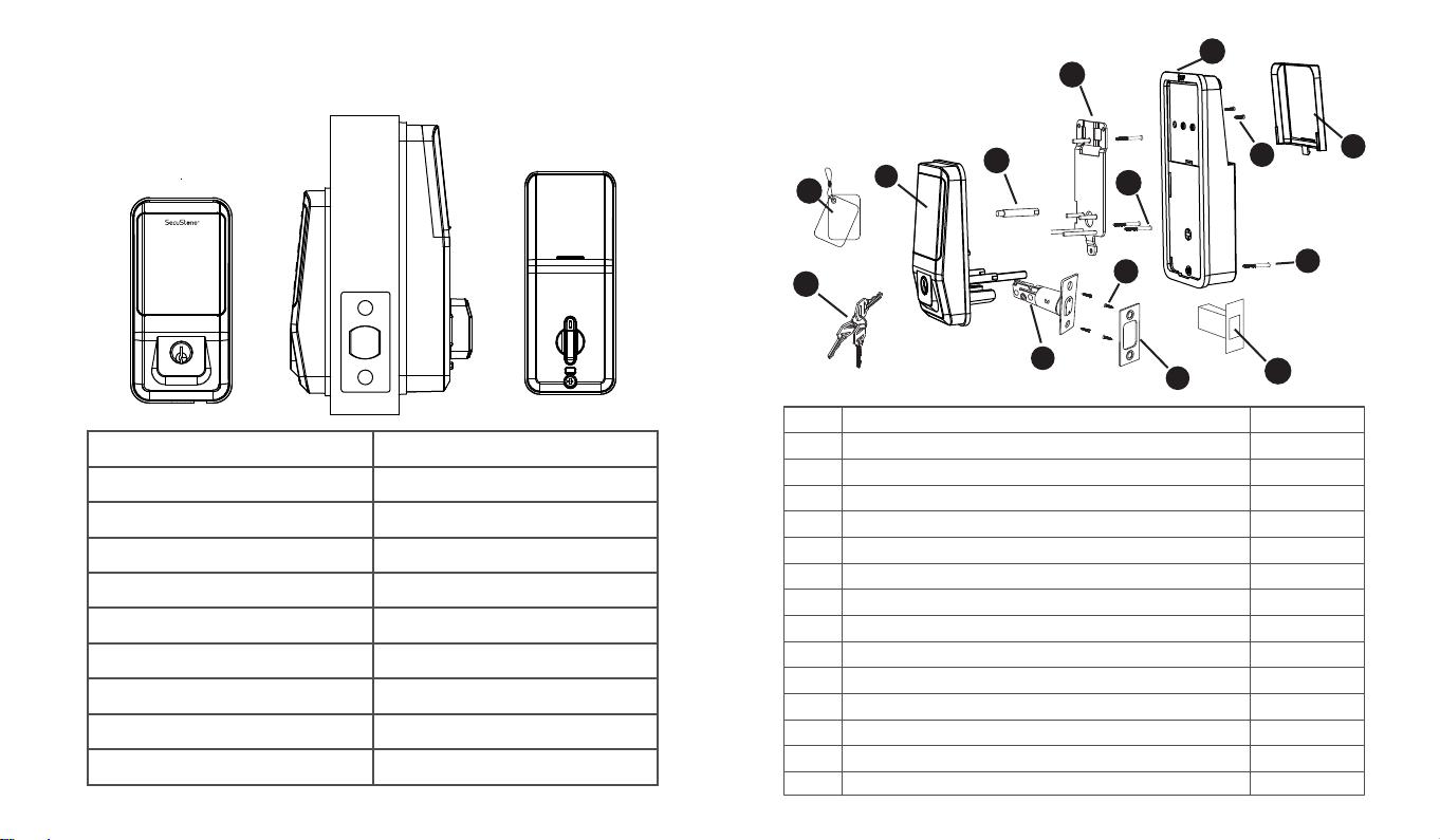
Package
(01) (02)
Bluetooth, Passcode, Key, IC Card
Part Quantity
A
B
C
D
E
F
G
H
I
J
K
L
M
3
1
2
1
4
1
1
1
4
1
3
1
1
Description
Key
Keypad
Double-screw Bolt
Latch
Wood Screws
Strike Plate
Box Striking Plate
Inside Mounting Plate
Flat Screw
Receiver Module
Short Flat Screw
Longest Flat Screw
Battery C
N2
IC Card
over
A
NBC
H
J
I
D
F
E
M
K
L
G

INSTALLATION MANUAL
1.Smarter and Safer
Smart Lock Front Door set out to provide extra home security with keyless codes,
Bluetooth unlock, anti-peep password and auto lock (5-200s) to keep your house
safe and sound.
2.Real Time Record
Through Keyless Door Locks for Homes APP, you could check the unlocking records
and incorrect password records from the Admin account in real time. And you’ll have
comfort in knowing your door’s status.
3.Fast Sharing and Convenient
With Smart Digital Door Locks for Homes, You can share code with friends and
guests valid for a few weeks,hours, or minutes, and revoke them whenever you need
to. Never worry about lost, stolen or copied keys again.
4.Easily Install and Smart Reminder
Just a screwdriver and a easy-to-follow instruction to easily install Door Locks with
Keypads. And when in low battery, Keypad Door Lock Deadbolt Set will alarm and
could be temporary charged by power bank.
Performance
Note: Install and test lock with door open to avoid being locked out
Tools Needed
Installation Step
Phillips Screwdriver Tape Measure Pencil Other Chiseling Tools
Note: When performing this operation, please take protective measures and be careful
of the metal edge not to injure yourself
1.Adjusting Latch Length
(03) (04)
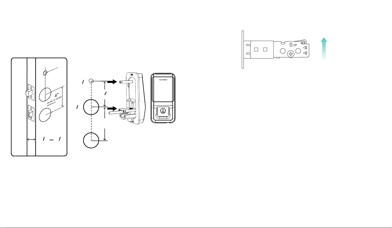
Hold the right part of the lock tongue with your right hand and turn the left iron piece
counter clockwise (about 15 degrees) with your left hand.
When the rectangular position of the 2-3/8”(60mm) tick mark changes from convex to
concave (as shown), slowly extend the locking latch, and then turn clockwise the
inside of the locking latch back to the rectangular position of 2-3/4”(70mm) scale.
1) Install Latch
Note:Need to keep this way up when inserting the latch.
2) Install Plate
a.Mark the outline of the faceplate, then take out the latch.
b.Chisel 1mm-2mm deep along the outline to allow the faceplate to be aligned with
the door edge.
c.Insert the latch into the door ,use 2 wood screws to secure latch
a.Identify the center of plate: Close the door to lay the latch bolt against the door frame. Mark
the the outline of the plate onto door jamb.
b.Drill 25mm deep at intersection of horizontal and vertical line of plat.
Chisel 1mm-2mm deep along the plate outline to allow the plate to be aligned with the door
frame.
1) Backset Determination
Backset is a distance from door edge to center of hole on door face.
2) Hole's Diameters
Using the marks as guide to drill holes Φ3/8''(10mm)----
Fasten Smart door lock Φ2-1/8''(54mm)
3) Door Thickness
The door thickness within 1-1/2'' to 1-7/8'' (38mm-48mm) are all suitable for the
keypad deadbolt handle set.
2.Check Door Dimensions
3.Install Lock
2"1
1
8"1
7
door thickness
123
456
789
*0 #
4"
8"2
7
8"2
1
8
"
3
center to center minimum
Insert the latch and ensure it is parallel to the door face.
(05) (06)

123
456
789
*
0 #
3) Install Keypad
4) Identify Door Handing
5) Adjust Thumb Turn Piece
C.Insert the plastic lock groove and the strike plate into door jamb tighten with wood screws.
Install double-screw bolt into
keypad inner plate.
Place IC wire, latch link bar and dou -
ble-screws through the holes on the
deadbolt, as the picture on the right
shows.
The door is "Left-handle" if the hinges are on the
left side of the door.
Whereas the door is "Right-handle" if the hinges
are one the right side of the door.
Rotate the thumb turn piece to “Horizontal Direction”
for Left-handle (open into room) door when in
unlock status.
Rotate the thumb turn piece to “Vertical Direction”
for Right-handle (open into room) door when in
unlock status.
Note: IC wire should be placed under latch.
After installing the front pad, roll the
handle spindle to test if it could work with
deadbolt or not. If could not, take out the
front pad and roll the latch link bar around
90 degree and try to install again untill it
could work with the deadbolt.
Note: Please place the IC line as shown in the figure to avoid the
lock latch out of control.
Pass the IC wire and the latch link bar to mounting plate.
Use 1 flat screw to secure with the keypad double-screw bolt.
Use 2 flat screw connect mounting plate with latch.
Left-handle
Hinge
1 2 3
456
789
*0 #
Right-handle
Hinge
1 2 3
456
789
*0 #
Left-handle Right-handle
(07) (08)
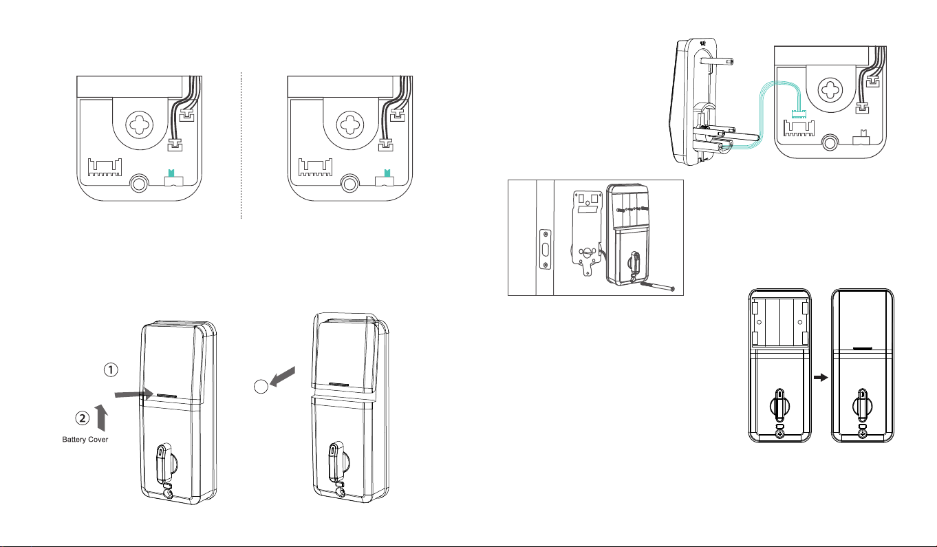
6) Adjust the Toggle Button of the Cover
Remarks:
1) Alkaline batteries are recommend in order to stabilize the power supply,
if you don't use alkaline, battery performance will be reduced greatly.
2) All settings will be retain in the memory even if the batteries are complete dead.
If batteries are complete dead, using power bank to unlock the door.
7) Install Battery Cover
8) Insert Battery and Install Back Battery Cover
To install the lock for left side handling,
ensure the toggle button on the back cover
assembly is set to "L".
Note:Ensure the thumb turn piece
and the toggle button of the
cover in right way.
To install the lock for right side handling,
ensure the toggle button on the back cover
assembly is set to "R".
L R L R
3
Push
L R
Use 2 short flat screw tighten the
receiver module inner battery groove.
Longest flat screw connect the receiver
module with door.
Insert 4pcs(AA)1.5V Alkaline batteries
and slide the battery cover back onto
the receiver module.
Connect IC wire to the white
port carefully.
(09) (10)

SMART INSTRUCTION
Pairing Lock to Phone App
1.Download the App ''TTLock''
Android Mobile Phone--Search ''TTLock'' from Google Play.
Apple Mobile Phone--please search ''TTLock'' from App Store.
2.Register and Login the Account
Login Register
Phone number/Email
Password
Login
Forgot Password?
Register
Enter your Email
Password between 6-20 chars
Confirm Password
Verification Code Get Code
Register
Phone
Login Register
Phone number/Email
.........
Login
Forgot Password?
X
TT LOCK App Operating
1.Account Information Change
When logging in "TTLock" App, you need set up an account contain account
password.Each account can be added with multiple smart device locks for
management.Once the smart lock is added, it will become the admin account
for the lock.
3.Match the Lock to the Application
When matching, follow the prompt steps of the program, you need to touch the screen after
installing the lock and installing the battery, match the blue icon lock , and set the name for
the lock.
Note: If the smart lock is in a non-addable state, Take out batteries to power off the lock about
5 seconds. Then, power on and long press manual button about 10 seconds.
Once hearing beep beep sound, the lock is reset successfully.
(11) (12)
Email

2.Lock/Unlock
Press for unlock, long press for lock.
It requires your smart phone and Bluetooth
lock to be within a certain range.
3.Send ekey
You can add another account on the app.
This way your family can also control the Bluetooth lock via the app.
Support authorized users to Limit time, Permanent, One-time, Recurring control smart lock.
Note: If you want remote control,
you need to connect to the gateway.
(13) (14)

Generate or customize the passcode of the Bluetooth lock.Generate or customize
permanent, one-time, time-limited, recurring passcode.
4.Generate Passcode
Manage the authorized accounts in ''Send eKey''.Admin can clear eKey, reset eKey,
send eKey etc.
5.ekeys
It records all passwords stored by the Bluetooth lock you had set. In addition, it can also
reset, generate, upload passwords.
6.Passcodes
Note: Generate the passcode to clear the passcode that Bluetooth lock stored by "Erase". Once used,
in addition to the admin passcode, other passcode will be cleared.
(15) (16)

It records the time and manner of the smart lock when someone opening or closing.
Manage your Bluetooth lock safely and efficiently.
9.Records
It have the function about the Bluetooth lock function setting, lock information setting, remote
unlocking, auto-off time, lock sound, time proofread, record reading, etc.
10.Settings
(18)(17)
It records all cards stored by the Bluetooth lock you had set. In addition, it can also
add cards, clear cards.
7.Cards
Authorized admin can add authorized administrators. The authorized administrator has the same
functions as the administrator, except for the authorized function.
8.Authorized Admin
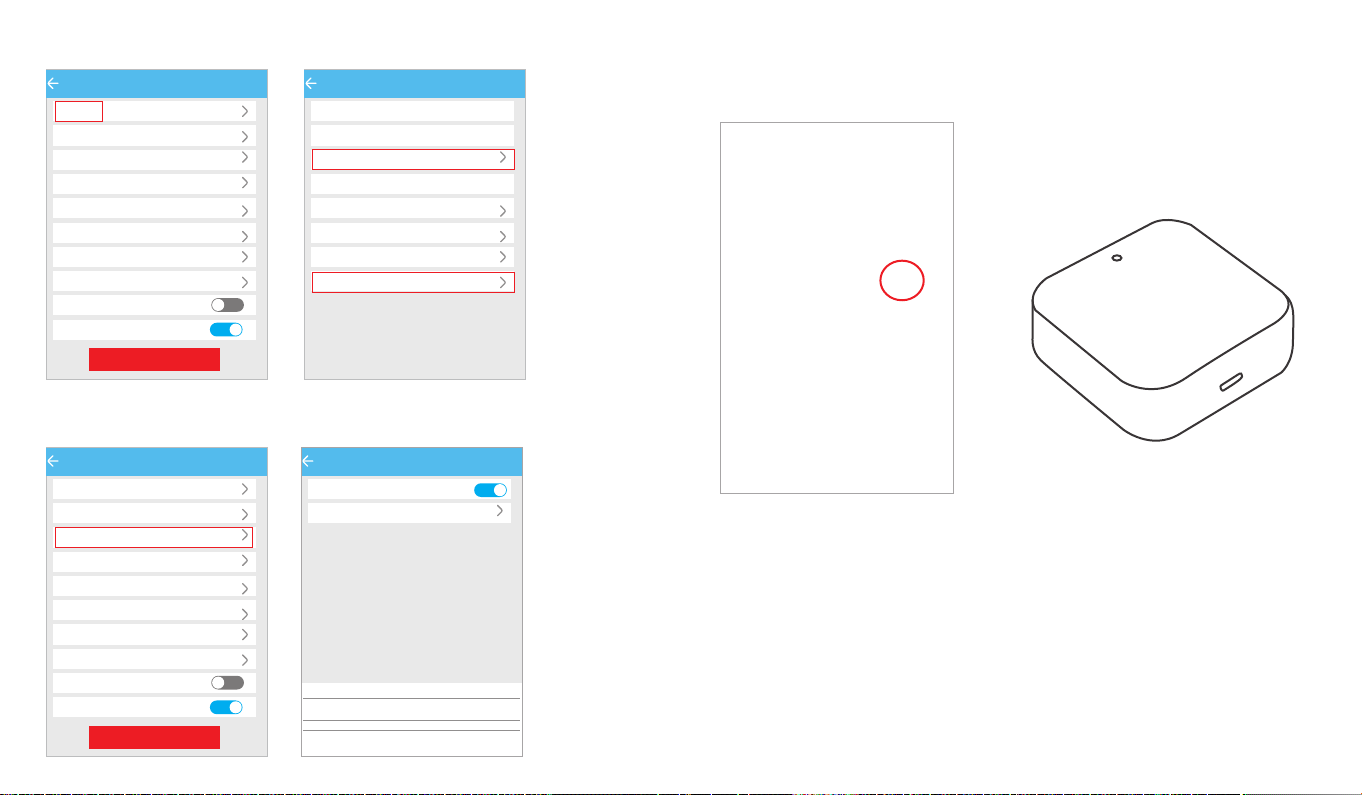
You can find the information about the lock such as battery power, admin passcode.
If you forget to lock your door often, you could to set ''Auto Lock''.
Set the time for automatic locking in your needs, so you don't have to worry about security
accidents due to being unlock.
Note:The admin passcode will not be cleared when erase passcode.
Settings
Basics
Unlock Remotely Off
180s
Auto Lock
Lock Sound
Lock Clock
Diagnosis
Read Operation Records
Firmware Update
Attendance
Unlock Notification
Delete
Settings
Basics
Unlock Remotely Off
180s
Auto Lock
Lock Sound
Lock Clock
Diagnosis
Read Operation Records
Firmware Update
Attendance
Unlock Notification
Delete
Basics
Lock Number M203T_4878ca
MAC/ID F9:75:D4:CA:78:48/1612875
100%
Battery
Validity Period Permanent
lock new
Ungrouped
Ungrouped
Lock Name
Lock Name
Lock Group
Admin Passcode
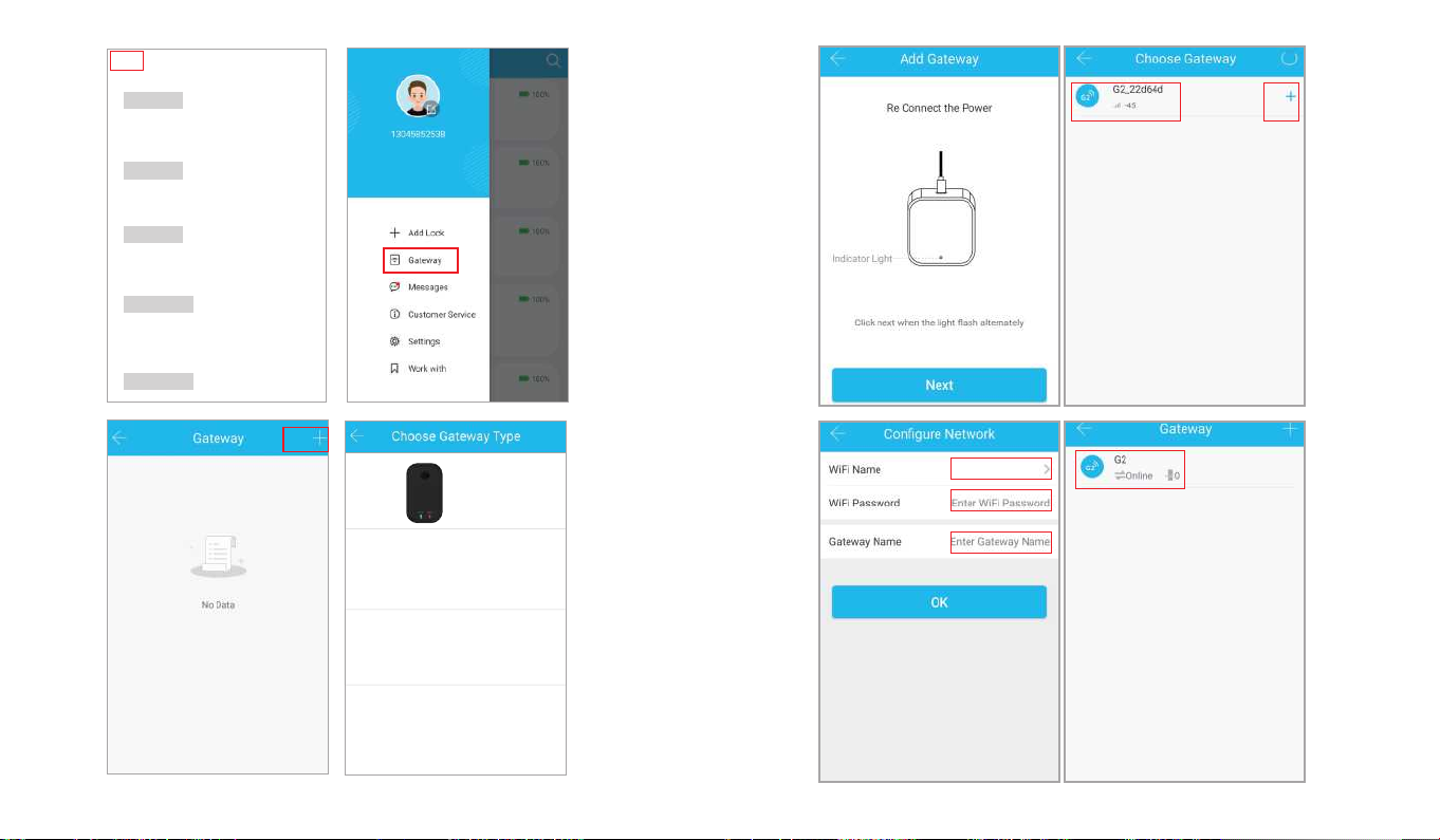
MATCH the Wi-Fi GATEWAY to the APPLICATION
Remote Control and Alexa would support after matching the Wi-Fi Gateway.
Click the button in the upper left corner of the page and enter relevant
information as prompted to add a gateway to your account.
Note: When the smart phone app matches the smart lock or the gateway, it is necessary to
enable Bluetooth and Wi-Fi.It can be successfully matched when your smart phone is close
to the lock and the Gateway.
Remote control support needs an extra additional Wi-Fi Gateway. Match the gateway,
smart phone, app then the smart lock can support remote control lock.
11.Remote Control
(19)(20)
Auto Lock
Auto Lock
180s
Current Setting
The lock will be locked after the time set above.
Cancel Time
10s
15s
30s
60s
Custom
Ok
(21)(22)
G1(Wi-Fi)
G2(Wi-Fi)
G3(Wired)
G4(4G)
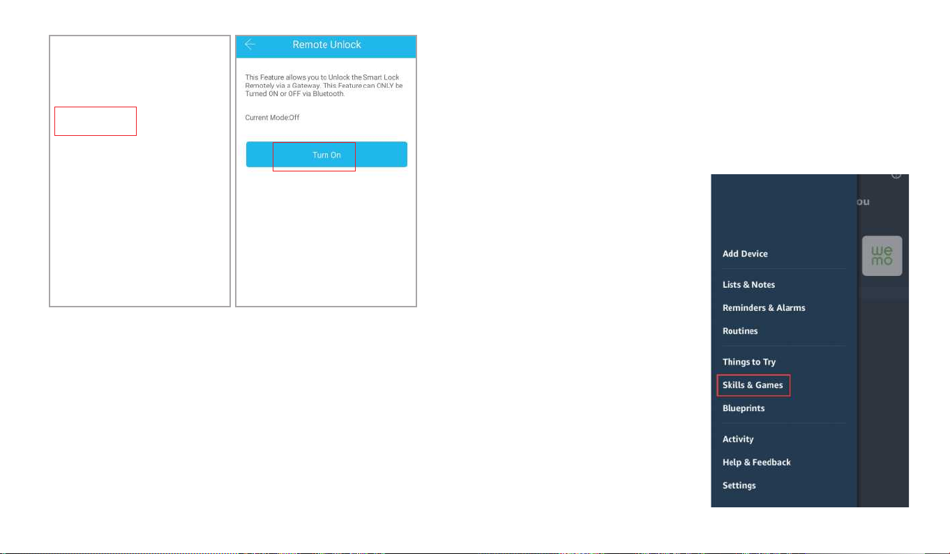
MATCH the TTLOCK APP to the ALEXA APP
After setting up to the gateway, authorize the TTLock app in the Alexa app and
login to the TTLock account to enable remote unlock and voice remote unlock.
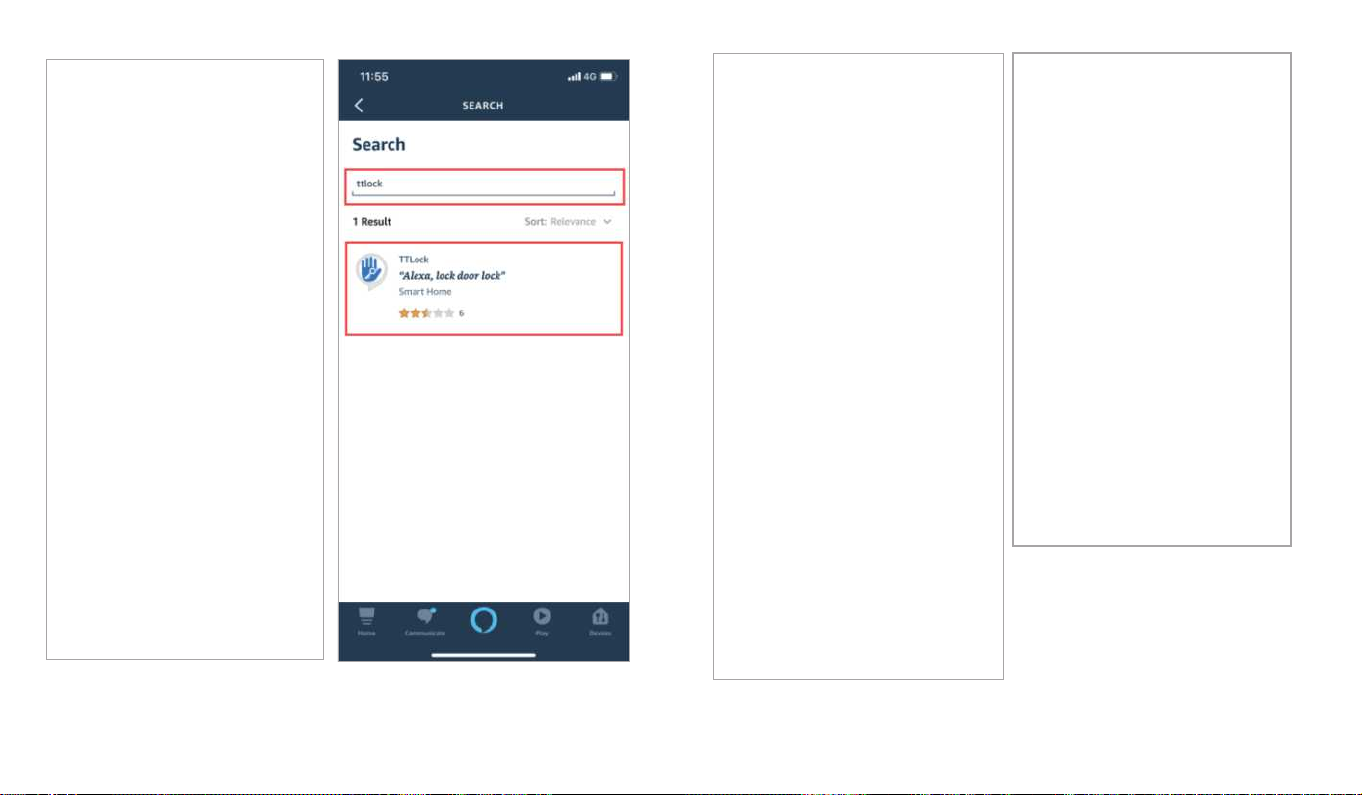
Select ''Skill & Games'' , input ''TTLock'' in the search bar, click
''ENABLE TO USE'' . And input TTLock account and password to finish the
authorization.
Note: If shows "Invalid Account and Password", please add "+1" at front of the account.
(23)(24)
(25) (26)

Press locks option,choose the lock you paired. Click the icon in the upper right
corner and slide the icon button of ''unlock by voice'' and ''unlock by voice''.
(27) (28)
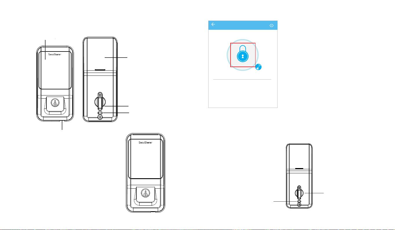
OPERATION INSTRUCTIONS
keep the door opened while programming to avoid being locking out accidentally.
Setting Admin Passcode
Battery Cover
Thumb Turn Piece
Reset/Deadbolt Button
Touch screen button
123
4 5 6
7 8 9
*0 #
Type C Backup PowerInterface
1 2 3
4 5 6
7 8 9
*0 #
The admin passcode can generated/set up after
matching the ''TTLock''app.
When not added to the phone,
enter " *12#123456#Custom Admin
Passcode#Confirm Passcode# " in Keypad.
(29)
Lock/Unlock
Via Key: The package contains two keys
that can be used directly through the
keyhole.
Rotate turn piece to unlock/lock from inside.
First time to long press deadbolt, when it make a clear sound
''DiDi'', all the passcode even app control couldn't unlock outside except admin passcode.
When long press it again until make another sound ''Di'', all are back to normal, the smart
lock in works.
Via Keypad: Enter the passcode then
press ''#''to unlock. Long press ''#''
and hold 2s for lock.
Via APP: Touch to unlock, long press to
lock. It supports at a certain distance
between smart phone and lock
Note: Remote control support need to
matching with Wi-Fi Gateway.
TT Lock
my Lock
Touch to Unlock, long Press to Lock
Send eKey Generate
Passcode
Records Settings
eKeys Passcodes
Deadbolt /Reset Button
Thumb Turn Piece
(30)
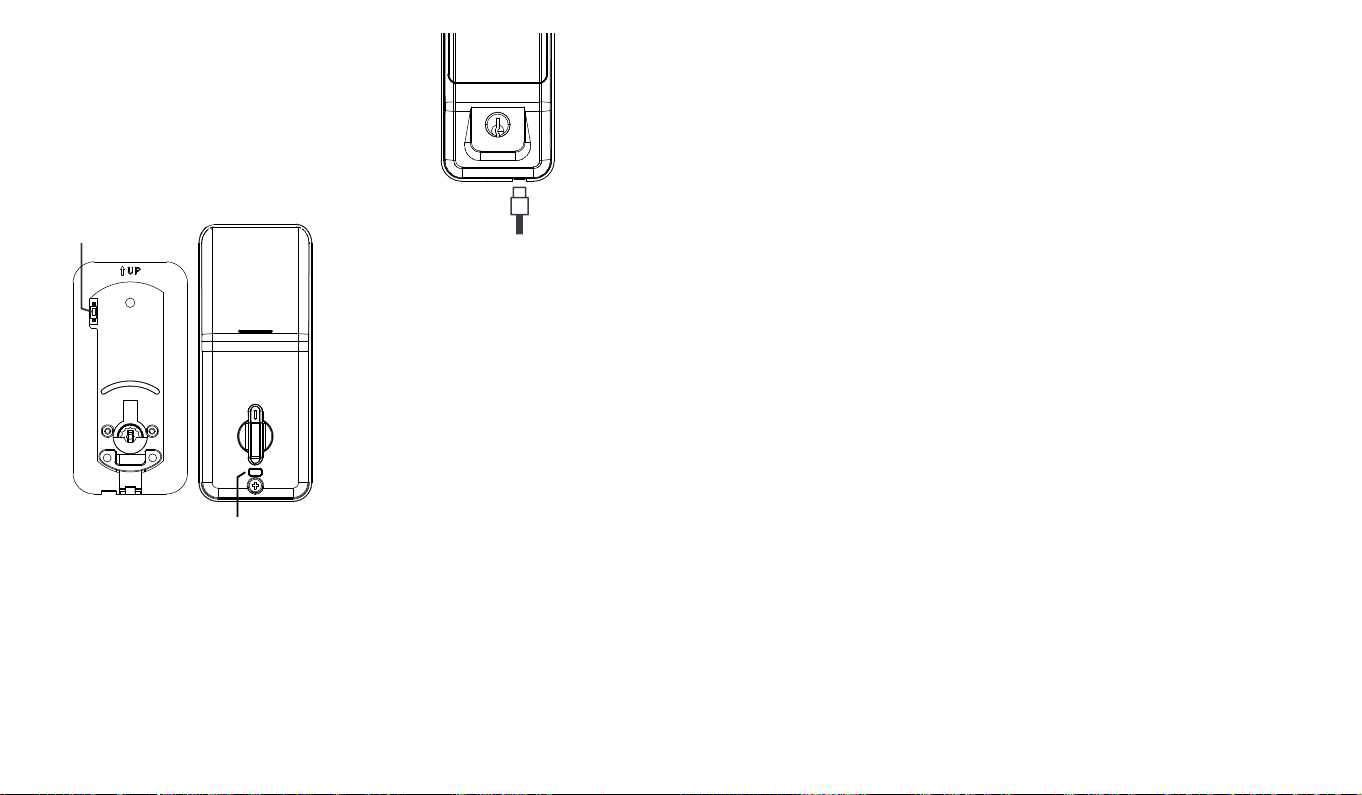
Battery Power Runs Out
Unauthorized Attempts Alert Mode
Reset Button
The smart lock sounds an alarm when
the battery is low.
You needed use Type-C USB supply
power to the Lock then unlock.
If the smart lock is in a non-addable state (the name is gray on the APP or cannot find),
please press and hold the reset button and try to connect again.
1. Take out one of the battery to power off the lock about 5 seconds. Then put in the battery, power on the lock
and long press the buttonabout 10 seconds.Once hearing "Please enter the initialization password", please
enter "000#" to confirm.You will receive a voice prompt after reset successfully.
2. Long press and hold the reset button in back panel for 10 seconds. Once hearing "Please enter the initialization
password", please enter "000#" to confirm. You will receive a voice prompt after reset successfully.
The smart lock has an unauthorized
attempts alert function.
Turn off the unauthorized attempts
alert mode:
Enter "*32# (admin password) #0#" on
the keypad.
Turn on the unauthorized attempts
alert mode:
Enter "*32# (admin password) #1#" on the
keypad.
Note: Keep the alarm button on the front panel
always pressed during install, otherwise it will
always be beeping while installing battery.
Note: This reset button is in the back panel.
Unauthorized Attempts
Alert Prompt
Reset Button
1 2 3
4 5 6
7 8 9
*0 #
(31)
FCC Statement:
Changes or modifications not expressly approved by the party responsible for compliance could
void the user's authority to operate the equipment.
This equipment has been tested and found to comply with the limits for a Class B digital device,
pursuant to Part 15 of the FCC Rules. These limits are designed to provide reasonable protection
against harmful interference in a residential installation. This equipment generates uses and can
radiate radio frequency energy and, if not installed and used in accordance with the
instructions, may cause harmful interference to radio communications. However, there is no
guarantee that interference will not occur in a particular installation. If this equipment does cause
harmful interference to radio or television reception, which can be determined by turning the
equipment off and on, the user is encouraged to try to correct the interference by one or more of
the following measures:
-- Reorient or relocate the receiving antenna.
-- Increase the separation between the equipment and receiver.
-- Connect the equipment into an outlet on a circuit different from that to which the receiver is
connected.
-- Consult the dealer or an experienced radio/TV technician for help
This device complies with part 15 of the FCC rules. Operation is subject to the following two
conditions (1)this device may not cause harmful interference, and (2) this device must accept any
interference received, including interference that may cause undesired operation.
FCC Radiation Exposure Statement:
This equipment complies with FCC radiation exposure limits set forth for an uncontrolled
environment. This equipment should be installed and operated with a minimum distance of 20cm
between the radiator and your body.
This transmitter must not be co-located or operating in conjunction with any other antenna or
transmitter.
Table of contents


