SEEDMASTER TOOLBAR User manual

SEEDMASTER –2023
TOOLBAR –ULTRAPRO II –NOVA TANK
OPERATOR’S
MANUAL


SEEDMASTER 2023
2
CONTENTS
CONTENTS................................................................................................................................................2
INTRODUCTION ........................................................................................................................................5
SAFETY......................................................................................................................................................6
TIRE TORQUE AND PSI SPECS ..............................................................................................................8
IN-CAB ELECTRICAL HOOKUP................................................................................................................9
RAVEN VIPER 4+ IN-CAB HOOKUP ....................................................................................................9
SEEDMASTER TOOLBOX AND MANUALS ...........................................................................................10
TRACTOR HYDRAULIC HOOKUPS .......................................................................................................11
SEEDMASTER MACHINE HYDRAULIC HOSES................................................................................11
HYDRAULIC CONNECTION REFERENCE CARDS...........................................................................12
MAIN HYDRAULIC BLOCK DETAILS......................................................................................................13
HYDRAULIC BLOCK GAUGES ...........................................................................................................13
MAIN BLOCK GAUGES.......................................................................................................................14
MAIN BLOCK VALVES, SOLENOIDS, AND PWMS ...........................................................................14
PRESSURE SETTING PROCEDURES...............................................................................................15
LIFT KIT................................................................................................................................................16
SMART OPENERS HYDRAULIC BLOCK DETAILS AND OPERATION ................................................17
SMART OPENERS HYDRAULIC BLOCK ...........................................................................................17
SMART OPENER OPERATION...........................................................................................................17
OPENER DETAILS...................................................................................................................................18
MANUAL SWITCH BOX INSTALLATION AND OPERATION.................................................................19
INSTALLATION....................................................................................................................................19
SWITCH BOX OPERATION.................................................................................................................20
FIELD OPERATION .............................................................................................................................21
ISOBUS TOOLBAR FUNCTIONS............................................................................................................22
HOME SCREEN LAYOUT ...................................................................................................................22
ISO TOOLBAR QUICK START PROCEDURE....................................................................................23
UNFOLDING, FOLDING, AND WING LOCKS.....................................................................................24
MASTER SWITCH CONFIGURATION................................................................................................26
PACKING PRESSURE SET UP AND OPERATION............................................................................26
PACKING PRESSURE OPERATION ON HOME PAGE.....................................................................28
LIFT KIT PRESSURE SET UP AND OPERATION..............................................................................29
SYSTEM INFORMATION HOME PAGE SET UP................................................................................30
SYSTEM ALARMS...............................................................................................................................32
SYSTEM DIAGNOSTICS PAGE..........................................................................................................33
ACTIVE ALARM PAGE ........................................................................................................................33
ULTRAPRO II ONFRAME TANKS (UPII).................................................................................................34
ULTRAPRO II ZONE COMMAND METER BOX (UPII).......................................................................34

SEEDMASTER 2023
3
UPII CALIBRATION PROCEDURE PRE-SETUP................................................................................35
UPII FAN PRESSURE GUIDELINES...................................................................................................37
ZONE COMMAND AIR COMPRESSOR..............................................................................................38
ZONE COMMAND AIR SYSTEM.........................................................................................................39
NOVA TANK.............................................................................................................................................40
NOVA ZONE COMMAND / METER BOX............................................................................................41
TUNABLE TOWER...............................................................................................................................42
ROMAFA DISTRIBUTION MANIFOLD................................................................................................43
NOVA PRODUCT SELECTION...........................................................................................................44
NOVA PRESSURE AND TOP-UP AIR ................................................................................................46
NOVA FAN PRESSURE GUIDELINES................................................................................................47
INDIVIDUAL METER INSPECTION.....................................................................................................48
WORK LIGHTS.....................................................................................................................................49
LID OPERATION..................................................................................................................................50
NOVA CONVEYOR OVERVIEW .........................................................................................................51
NOVA CONVEYOR CONTROLS.........................................................................................................51
KAR-TECH WIRELESS REMOTE.......................................................................................................52
SYNCHRONIZING THE REMOTE TO THE RECEIVER.....................................................................52
CONVEYOR OPERATION...................................................................................................................53
SEEDMASTER APP.................................................................................................................................54
ISOBUS RCM FUNCTIONS.....................................................................................................................57
HOME SCREEN LAYOUT ...................................................................................................................57
ISO RCM QUICK START PROCEDURE.............................................................................................59
RCM MAIN (HOME) PAGE ..................................................................................................................60
CATCH TEST CALIBRATION PROCEDURE......................................................................................63
APPLIED PRODUCT CALIBRATION PROCEDURE ..........................................................................67
RCM SETUP PAGE..............................................................................................................................70
CONTROL VALVE SETUP PAGE .......................................................................................................72
SCALE CALIBRATION.........................................................................................................................73
RCM TOTALS PAGE............................................................................................................................75
RCM DIAGNOSTICS PAGE.................................................................................................................77
GENERAL TROUBLESHOOTING .......................................................................................................80
GRANULAR PRODUCT CONTROL SETUP (DEALER OR SEEDMASTER ASSISTED ONLY).......81
SINGLE LIQUID PRODUCT CONTROL SETUP (DEALER OR SEEDMASTER ASSISTED ONLY).84
EXISTING RCM LIQUID PRODUCT CONTROL SETUP (DEALER OR SEEDMASTER ASSISTED
ONLY)...................................................................................................................................................86
REMOTE TANK MONITOR......................................................................................................................89
SELECT ACTIVE RCM.........................................................................................................................89
VIEWING RCM SERIAL NUMBER ......................................................................................................89

SEEDMASTER 2023
4
TOGGLING BETWEEN RCMS (UPII, NOVA, LIQUID) .......................................................................89
READ AND ZERO TANK WEIGHT VIA TANK/BIN INFO....................................................................90
READ AND ZERO TANK WEIGHT VIA SCALE ..................................................................................91
REMOTE CATCH TEST CALIBRATION PROCEDURE .....................................................................92
REMOTE TANK MONITOR TROUBLESHOOTING ............................................................................96
VIPER 4+..................................................................................................................................................97
POWER BUTTON AND STATUS ........................................................................................................97
VIPER 4+ BUILT-IN SELF TEST..........................................................................................................97
DEVICE SHUT DOWN.........................................................................................................................97
VIPER 4+ MAIN SCREEN NAVIGATION ............................................................................................98
JOB PROFILE PANEL..........................................................................................................................99
ADMINISTRATOR OR USER PANEL................................................................................................100
MACHINE CONFIGURATION PANEL...............................................................................................101
PRODUCT CONFIGURATION PANEL..............................................................................................101
CREATING JOB PROFILES ..............................................................................................................102
CREATING PRODUCT PROFILES ...................................................................................................103
AUTO ZONE COMMAND LOOK AHEAD TIME SETUP ...................................................................104
VIPER 4+ JOB QUICK START PROCEDURE ..................................................................................105
VIPER 4+ RUN SCREENS.................................................................................................................106
MANAGING SCREEN LAYOUTS......................................................................................................107
CREATING A FLIP MAP AND BOUNDARY FOR FIELD..................................................................108
CREATING AN INSIDE FLIP MAP.....................................................................................................110
SEEDING THE VIRTUAL PASS ........................................................................................................110
LOADING A PREVIOUSLY CREATED FLIP MAP ............................................................................111
VIPER 4+ FILE MAINTENANCE........................................................................................................112
3RD PARTY GPS.................................................................................................................................113
SETTING THE TRACTOR MEASUREMENTS..................................................................................114
IMPORTING PRESCRIPTION MAPS................................................................................................115
LOADING RX MAPS WITH A JOB.....................................................................................................116
UPDATING ECUS VIA VIPER 4+ ......................................................................................................118
WIFI OR TETHERED REMOTE SUPPORT ......................................................................................119
SYSTEM ELECTRICAL DRAWINGS.....................................................................................................120
IN-CAB VIPER 4+...............................................................................................................................120
ISO TXB ONLY...................................................................................................................................121
REMOTE TANK MONITOR................................................................................................................121
NOTES ...................................................................................................................................................122

SEEDMASTER 2023
5
INTRODUCTION
Thank you for purchasing a new SeedMaster unit. This manual will assist you in becoming a safe and
efficient operator. The crops you grow because of the proper use of the unit will be your reward for
spending some time studying this manual.
If problems arise, SeedMaster Manufacturing’s dealership network can provide clarification and
correction. It is important that all SeedMaster units maintain a solid reputation.
SeedMaster Manufacturing would like to take this opportunity to thank you, our valued customer, and
our valued dealer, for showing your confidence in purchasing and representing a quality SeedMaster
product.

SEEDMASTER 2023
6
SAFETY
Please be SAFE! Carefully read and understand all safety alerts and warnings in this manual and all
safety decals on the SeedMaster drill and tank. Ensure that anyone who is going to use the SeedMaster
drill and tank reads and understands the Operator’s Manual. We recommend that only mature and well-
trained or experienced persons operate this product. We advise that periodic visual checks continue as
a mandatory part of the implement operating procedure. Conduct regular maintenance checks on
fasteners, hydraulic connections, etc. Always follow safety precautions. Serious INJURY or DEATH can
result from improper operating practices.
Safety notices are one of the primary ways to call attention to potential hazards.
This Safety Alert Symbol identifies important safety messages in this manual. When you
see this symbol, carefully read the message that follows. Be alert to the possibility of personal injury
or death.
Read and understand the Operator’s Manual and all safety signs before operation or
maintenance.
Do not allow riders on any part of the equipment.
Install and properly secure all shields and guards before operating the seeder.
Keep hands, feet, clothing, and hair away from moving and/or rotating parts.
Beware of all power lines and other overhead obstructions. Know the transport height and width
of your SeedMaster drill and tanks. Ensure that minimum safe working distances are always
maintained from any obstruction.
Before servicing, adjusting, repairing, refilling, or unplugging: stop the engine, remove the engine
key, set the park brake, disengage the hydraulics, and wait for all moving parts to stop.
Ensure your seeder is properly marked as required by the local highway and transport authorities.
Make sure the “Slow Moving Vehicle” sign, lights, and all reflectors are in place, clean, and visible
to overtaking or oncoming traffic.
Store a fully stocked first-aid kit in a visible, accessible place for use in case of an accident.
Keep a fire extinguisher in an accessible location.
Be sure that the area is clear of people before starting or moving your machine.
Do not work around or under the raised wings unless the wings are securely chained in the
transport position.
In the event that wheel and tire assemblies must be raised off the ground for maintenance, block
the implement up securely.
Use extreme caution when working around or with high-pressure hydraulic systems. Depressurize
the system when connecting or disconnecting the hose couplers.
Wear heavy gloves and eye protection when searching for suspected hydraulic leaks. If an injury
occurs, seek immediate medical attention as infection and toxic reaction could develop. Use a
piece of cardboard or wood (instead of hands) when searching for such leaks.
Never wear baggy or frayed clothing or hanging jewelry when working around or on any of the
drive system components.
When performing a product catch for meter calibration, keep hands and clothes well clear of
rotating components. Be aware that when the hydraulics are activated, rotation may start
unexpectedly at any time.
We recommend that all maintenance and adjustments on the seeder be made when the
implement wings are lowered.

SEEDMASTER 2023
7
Store and transfer gasoline, solvents, cleaners, or any flammable liquids only in safety standard
(i.e. CSA) approved containers.
Clean and inspect all components in the hydraulic system on a regular basis.
Replace all worn, cut, abraded, flattened, damaged, or crimped hoses and metal lines. Do not
repair hydraulic components with tape, clamps, or cements. The system operates under extremely
high pressure; such repairs will fail and create hazardous and unsafe conditions.
Before applying pressure to the hydraulic system, make sure all connections are tight. Ensure
lines, hoses, and couplings are not damaged.
Ensure that the seeder is properly and safely connected to the tractor.
Transport per local regulations for width and height.
Follow all road safety regulations for your state or province.
Store the seeder on a firm, level surface.
Store with wings down.
Have a qualified tire dealer or service person perform tire maintenance. Failure to follow proper
procedures when mounting a tire on a wheel or rim can cause an explosion that may result in
serious injury or death.
Always keep safety decals and signs clean and legible. Replace safety decals and signs that are
missing or have become illegible.
Ensure proper use of wing lock-up chains in transport.
Always use hitch safety chain.
Do not transport at high speeds on loose gravel behind a truck or a tractor.
Do not transport with product in tanks.
Ensure proper hook-up of safety lights.
Maneuver machine to ensure castors are moving freely before going onto roads.
Do not transport at speeds higher than that recommended on tires (25 mph or 40 kph).
Check all transport wheel nuts after 100 miles and periodically thereafter. (See PAGE 8).
Use proper tire inflation pressures (SEE TIRE TORQUE AND PSI SPECS, PAGE 8).

SEEDMASTER 2023
8
TIRE TORQUE AND PSI SPECS
TIRE SIZE
TORQUE REQUIREMENTS (FT. LBS.)
MAXIMUM PRESSURE RATING (PSI)
12.5L15 (10 PLY)
200
44
12.5L15 (Hwy)
200
90
380/55-16.5
200
72
750/65R26
450
35
800/65R32
450
35
1050/50R32
450
35
Dual 710/70R38
750
23
SEEDMASTER 6012 ULTRAPRO II 360 WITH NOVA 520
SEEDMASTER 2023
9
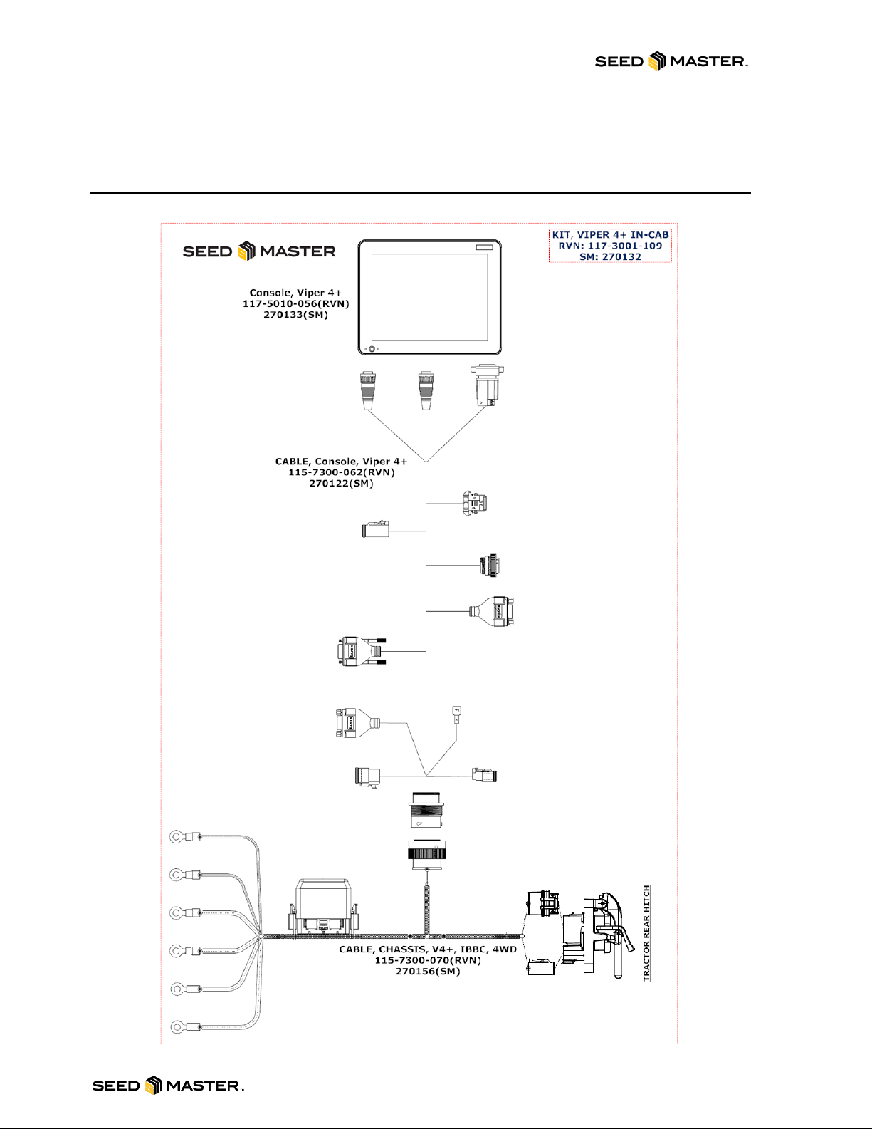
IN-CAB ELECTRICAL HOOKUP
RAVEN VIPER 4+ IN-CAB HOOKUP
SLINGSHOT POWER
GPS IN
SWITCHED POWER OUTPUT
ISOBUS DIAGNOSTICS PORT
RAVEN CANBUS
ISOBUS TERMINATOR
NOT USED
NOT USED
NOT USED
BATTERY CONNECTIONS

SEEDMASTER 2023
10
SEEDMASTER TOOLBOX AND MANUALS
SeedMaster offers a factory option toolbox to hold any spare parts, tools, or accessories to keep your
seeding operation moving. It is located on the “A-Frame” support beam in the middle of the hitch. The
toolbox has a seal to help reduce the amount of dust and foreign material from contaminating or soiling
the contents. Beside the toolbox is a container that contains your machine-specific manuals. This
container is dust and water tight to ensure that your manuals stay intact in any weather or field
conditions.
For machines with tow-between distribution, or a front-mounted tank, the toolbox will be located at the
top of the “A-frame” beside the main-frame castor.
NOTE: Do not stand or walk on the toolbox!

SEEDMASTER 2023
11
TRACTOR HYDRAULIC HOOKUPS
SEEDMASTER MACHINE HYDRAULIC HOSES
HOSE MARKING CONVENTION: Each hose pair has been assigned a unique colour. The hose with 1
colour band is pressure, and the hose with 2 colour bands is return.
OPENER RAISE/LOWER HOSES: Red Tagged Lines –The two ½” Direct Opener Lift & Lower
hydraulic lines with red colour bands are the opener lift and lower lines. These lines are connected to
one tractor remote. The hose with 1 red band is opener down pressure. The hose with 2 red bands is
pressurized to raise the openers. The openers are held up in transport with a Pilot Operated Check
Valve. This maintains the pressure on the opener up pressure circuit for long transport and to facilitate
unhooking under lift pressure. Leave the pressure engaged to operate the Smart Openers.NOTE: See
page 17 for operation instructions.
SYSTEM PRESSURE HOSES: Green Tagged Lines - The two 1/2” hydraulic lines with the green colour
bands are used to activate the block and raise and lower the wings. These lines are connected to one
tractor remote. In the field, operating position for this remote is locked-on to provide continuous pressure
to the block via the line with 1 green band. Pressure should be adjusted and set between 2600-3000 psi
by using the tractor remote flow control.
SEED AND FERT FAN HOSES ONFRAME: There may be one or two ¾” fan pairs. If you are running
an UltraPro II 350 or 360 machine, the single fan hoses will be tagged with 1x orange (pressure) and 2x
orange (return). If you are running an UltraPro II 540 machine, the seed fan hoses will be tagged with 1x
orange (pressure) and 2x orange (return) and the fertilizer fan will be tagged with 1x purple (pressure)
and 2x purple (return).
SEED AND FERT FAN HOSES NOVA: If you are running a NOVA Cart the seed fan hoses will be
tagged with 1x yellow (pressure) and 2x yellow (return) and the fertilizer fan will be tagged with 1x blue
(pressure) and 2x blue (return).
Ensure that you connect the right pair of hoses together on your tractor.
CASE DRAIN HOSE: Drills and tanks are set up with ONE 1/2" case drain/return line (zero back
pressure). This line has a ½” NPT full open return coupler without any restriction or back pressure.
Ensure this return line is routed to your tractor properly without any possibility of back pressure.
Improper connection or undersized return lines on the tractor may cause inaccuracies in operation and
the possibility for severe damage to the drill’s hydraulic system. SeedMaster Manufacturing
recommends using the factory connections provided with the drill and tank.

SEEDMASTER 2023
12
HYDRAULIC CONNECTION REFERENCE CARDS
SeedMaster machines come in several different configurations. Please refer to your configuration below.
Ensure that you are hooking the pressure and return hoses to the appropriate remotes on your tractor:
Pressure to Retract, Return to Extend.
OnFrame UPII 350/360/540 Only Hydraulic
hookup
OnFrame UPII 350/360 and Nova Hydraulic
hookup
SEEDMASTER 2023
13
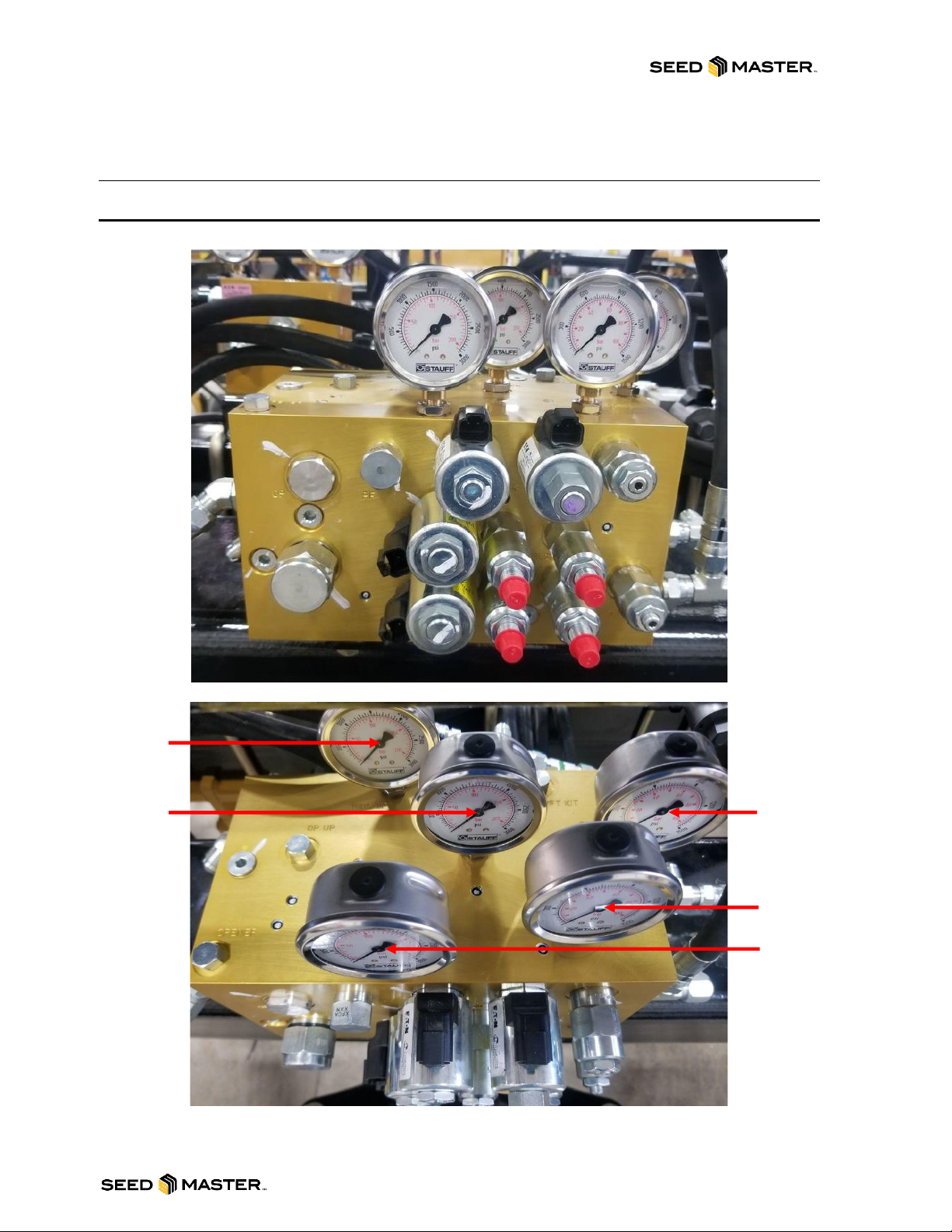
MAIN HYDRAULIC BLOCK DETAILS
HYDRAULIC BLOCK GAUGES
RAVEN
WING DOWN
TANK
SYSTEM
PRESSURE
WING UP

SEEDMASTER 2023
14
MAIN BLOCK GAUGES
WING UP: The WING UP gauge reads the amount of pressure applied and required for lifting and
should read 0 psi until folding up. A positive reading during field operation is an indication of back
pressure on the system.
RAVEN: The RAVEN gauge reads the amount of pressure being supplied to the hydraulic metering
motors.
TANK: The TANK gauge reads the amount of pressure being returned to tank.
WING DOWN: The WING DOWN gauge reads the amount psi being applied to the wings while they are
down and in field operation.
SYS: The SYS gauge reads the amount of system pressure being applied to the system. System
Pressure is the main pressure supply for the WING UP/DN, LIFT KIT, RAVEN (METERING) circuits.
2600-3000 psi indicates tractor working pressure to block. Pressure fluctuation can indicate back
pressure or lack of flow to the circuit. Adjust tractor flow as necessary to hold within range.
MAIN BLOCK VALVES, SOLENOIDS, AND PWMS
LEFT WING LOCK: This on/off solenoid turns the oil flow on/off to the left wing cylinders.
RIGHT WING LOCK: This on/off solenoid turns the oil flow on/off to the right wing cylinders.
OUTER WING LOCK: This on/off solenoid turns the oil flow on/off to the outer wing cylinders.
FAST WING: This on/off solenoid turns the oil flow on/off to the inner wing cylinders.
HIGH PRESSURE WING RELIEF (THERMAL): High tank pressure cut off cartridge is preset set at
3500 psi
TANK LINE RELIEF: The tank line relief cartridge is preset at 450 psi. If the cartridge exceeds 450 psi it
will relieve to the atmosphere.
WING-DOWN PRESSURE: 180 psi (NOTE: REQUIRED PRESSURE SETTING MAY VARY FROM
FACTORY PRESET TO SPECIFIC TRACTOR AND DRILL COMBINATIONS).
HIGH
PRESSURE
WING RELIEF
(THERMAL)
OUTER WING
LOCK
LEFT WING
LOCK
RIGHT WING
LOCK
FAST WING
WING DOWN
PRESSURE
TANK LINE
RELIEF
FAST WING
PRESSURE
LIFT KIT
RAVEN (METER)
SUPPLY
PRESSURE
SAFETY SHIFT
VALVE

SEEDMASTER 2023
15
Wing-Down pressure may need to be increased if the wings start to float and not contour correctly while
in the seeding position or if a positive Wing-Up pressure is detected.
Wing-Down pressure may need to be decreased if the wings become too rigid while in the
seeding position.
RAVEN (METER) SUPPLY PRESSURE: 2000 psi
LIFT KIT: 200 psi
FAST WING PRESSURE: 1500 psi
SAFETY SHIFT VALVE: The safety shift valve will shut the hydraulic flow off to the block if back
pressure reaches 240 psi on tank line to prevent system damage.
PRESSURE SETTING PROCEDURES
Setting Wing-Down Procedure (WING-DOWN PRESSURE)
The Wing-Down pressure is the amount of hydraulic pressure being applied to the inner and outer wing
circuits; the oil supply is supplied from the system pressure. The Wing-Down Pressure is required so the
wings will contour while travelling through the field. SeedMaster requires Net Wing-Down Pressure. To
determine your net value, subtract your wing-up pressure from your current wing-down pressure (ie. 380
PSI wing-down –200 PSI wing-up = 180 PSI net wing-down).
-To adjust the WING-DOWN PRESSURE, loosen the jam nut on the cartridge in port WD on the
main block. Turn the cartridge in to increase the pressure, and out to decrease the pressure.
When the desired pressure is set, re-tighten the jam nut.
Setting Wing Unfold Procedure (FAST WING PRESSURE)
The wing unfold pressure is the amount of hydraulic pressure being applied to the inner and outer wing
circuits while the tool bar is unfolding. This is also known as the Fast Wing Pressure. If the wings are not
unfolding the pressure will need to be increased. The oil supply is supplied from the system pressure.
-To adjust the FAST WING PRESSURE, loosen the jam nut on the cartridge in port FW PRESS
on the main block. Turn the cartridge in to increase the pressure and out to decrease the
pressure. When the desired pressure is set, re-tighten the jam nut.
Active Wing Brace Check
The Active Wing Brace supports the wing
sections of the frame. While in the field, a
hydraulic cylinder pulls the rear of the wing
section forward counteracting draft while
seeding. The hydraulic pressure comes
from the opener cylinder hydraulic circuit.
The higher the pressure is set to the active
wing brace circuit, the more it will pull the
rear wing square. When the packing
pressure is increased, so is the amount of
pull on the brace to a set maximum.
-Adjusting the wing brace: Start
by unfolding the SM drill and
activating the system pressure.
Next, pressure the openers down with the opener pressure switch and adjust the shank down
hydraulic pressure to 1000psi, activating the active wing braces. After the system has been
completely pressurized, inspect each wing brace cylinder indicator. They should be fully
retracted against the plate limiter. If not, please adjust the length of the active wing brace using
the threaded link. The braces should be periodically checked to ensure proper adjustment. This
will ensure your frame integrity remains true and helps increase the longevity of your machine.
Meter Drive Pressure Setting Procedure (RAVEN METER SUPPLY PRESSURE)
The Meter Drive Pressure is the amount of hydraulic pressure allowed to the hydraulic metering drives.
The torque to the metering drives increases as the pressure increases. Do not exceed 2200 psi. The oil
supply for RAVEN METER SUPPLY PRESSURE is supplied from the system pressure.
-To adjust the RAVEN METER SUPPLY PRESSURE, loosen the jam nut on the cartridge in port
RAVEN on the main block. Turn the cartridge in to increase the pressure and out to decrease
the pressure. When the desired pressure is set, re-tighten the jam nut.

SEEDMASTER 2023
16
LIFT KIT
LIFT KIT: The Lift Kit is designed to decrease the weight on the main frame front caster wheels during
field operation. It is hydraulically operated utilizing supply oil from the main hydraulic block’s system
pressure. The Lift Kit increases floatation by redistributing weight from the front caster wheels of the drill
forward to the tractor hitch and backwards to the rear of the drill. The reduced weight and draft on the
drill then adds weight and traction to the rear of the tractor. It also reduces stress on the hitch and frame
of the drill when seeding in wet conditions.
Setting Lift Kit Procedure (Auto-PWM)
-See page 30 for in cab pressure readout, pressure adjustment, and operating modes for this
feature.

SEEDMASTER 2023
17
SMART OPENERS HYDRAULIC BLOCK DETAILS
AND OPERATION
SMART OPENERS HYDRAULIC BLOCK
The Smart Openers block contains the main functions of your SeedMaster openers: raising, lowering,
and down-pressure. These functions are controlled by a Master ON/OFF solenoid and coil to raise and
lower, and a PWM valve for down-pressure. The Smart Openers block is located on the first rank behind
the main block. For it to operate, you will leave the connected tractor hydraulic remote engaged during
field operation. Recommended maximum flow for this remote is 75%.
SMART OPENER OPERATION
LOWER, LIFTING, THEN LOWERING THE OPENERS
LOWER:
1. LOCK ON REMOTE TO SUPPLY OPENERS WITH HYDRAULIC PRESSURE.
2. CYCLE MASTER FOOT SWITCH FROM OFF TO ON AND LEAVE THE MASTER SWITCH
“ON”. OPENERS WILL LOWER AND BUILD PRESSURE TO YOUR PRESET VALUE.
LIFT:
3. AFTER THE TOOLBAR IS COMPLETEY OVERLAPPED INTO AN APPLIED AREA, SHUT
THE MASTER FOOT SWITCH OFF. OPENERS WILL LIFT.
4. COMPLETE THE TURN.
LOWER:
5. CYCLE MASTER FOOT SWITCH FROM OFF TO ON AND LEAVE THE MASTER SWITCH
“ON” OPENERS WILL LOWER AND BUILD PRESSURE TO YOUR PRESET VALUE.

SEEDMASTER 2023
18
OPENER DETAILS
The opener is preset for seed and fertilizer depth. The seed depth is factory set at 3/4” below the
packed surface and the fertilizer depth is factory set approximately 3/4” below and 1 ½” to the side of
the seed.
In varying field conditions,
soil types, and moisture
conditions, it may be
required to adjust the
openers from the pre-set
depths. We recommend
seeding cereals, oil seeds,
and all other products at the
determined seed and
fertilizer depths desired by
the owner/operator. The
notches on the hub plate
correspond to 1/4” changes
in depth, with the inverted
notch being the factory pre-
set depth of 3/4”.
To change depth using the SeedMaster Quick
Depth Adjusting Tool, simply loosen the nut on
the slotted portion of the hub plate and rotate
packer tire upwards to increase depth, or
downwards to decrease depth.
Semi-pneumatic packer tires are a standard
feature on all SeedMaster drills. There is no
internal air pressure that needs to be checked.
The resulting dent the packer wheel leaves
behind is dependent on soil type and hardness.
The variation in dent depth does not affect the
crop since the seed depth is always monitored
from the packed surface.
*Avoid the temptation to harrow after seeding, as harrowing will reduce the uniformity of crop
emergence and reduce yield potential. The dent left by the packer wheel and the loose soil tossed to the
side as the openers move through the soil may appear rough at first glance, but you will find the residue
and soil settles over time leaving just the ripple of the packer wheel. This dent provides several
agronomic benefits.
Warning: Avoid turning your drill very short. The opener is designed to seed primarily in
straight lines. A sharp turn will cause the openers to be dragged sideways, resulting in an
improper seeding job and undue stress on the openers. Never turn so short that the inside
openers move straight sideways or backwards.
Always store the drill for extended periods of time in the unfolded wing position. This is to avoid
water getting into the packer tire and wing wheel bearings. This is very important for winter
storage.

SEEDMASTER 2023
19
MANUAL SWITCH BOX INSTALLATION AND
OPERATION
INSTALLATION
The SeedMaster Manual Switch Box consists of 7 switches, a 20-amp fuse, and a wiring harness.
1. Place the electrical box
in the cab at a
convenient location.
2. Mount the box at the
chosen location by
opening the box and
fastening the back panel
at a desired location in
the tractor cab.
3. Use a 14-gauge wire to
provide ground to the
white wire. This can be
from the battery, or from
your tractor’s switched
power.
4. Use a 14-gauge wire to
provide 12-volts to the
red wire. This can be from the battery, or from your tractor’s switched power.
5. Run the harness through the cab to the hitch. Connect the plugs at the hitch to the mating plugs
on the drill.
BLUE AUXILIARY WIRE
If you are using our switch box in combination with a third-party metering system, you may be able to
link the two using the blue auxiliary wire (provided both are operating at 12 volts). This allows the
operator to activate only one switch for a headland turn. There are two different ways the blue wire can
be used:
1. Use the blue wire to apply 12-volt signal to activate a relay for 3rd party metering devices. Power
is supplied to the blue wire when the opener pressure on/off switch is activated from the
SeedMaster control box.
2. If you are using another manufacturer’s 12-volt product metering system, you can use the blue
wire to signal the SeedMaster Manual Switch Box “opener pressure on/off switch”. This is done
by back-feeding 12-volt power to the blue wire. If this is your choice, always leave the switch in
the off position.
NOTE: The blue auxiliary wire is not a ground. It may or may not be used depending on seeding
system installation.
This manual suits for next models
2
Table of contents
Other SEEDMASTER Farm Equipment manuals


Popular Farm Equipment manuals by other brands


ATI Corporation
ATI Corporation Level Best Grader Blade Operator's & parts manual

Prevue Hendryx
Prevue Hendryx ECONO-1614 Assembly

PEQUEA
PEQUEA TT6101 Operator's manual

Thurston
Thurston BLU-JET AT2000 Assembly and operators manual

GSi
GSi 40 Series Construction manual

MacDon
MacDon D1X Series Assembly instructions

Hardi
Hardi MERCURY 2000 Instruction book

Galebreaker
Galebreaker Bayscreen Installation and operating instructions

EJWOX
EJWOX 43 Gallon Tumbling Composter manual

Kubota
Kubota RA2584 Operator's manual

KUHL
KUHL FC 303 GL Pre-delivery instructions

LOFTNESS
LOFTNESS Battle Ax 207460 Owner's manual and parts book