SEEDMASTER ULTRA SR User manual

SEEDMASTER –2023
ULTRA SR
OPERATOR’S
MANUAL


SEEDMASTER 2023
2
CONTENTS
CONTENTS................................................................................................................................................2
INTRODUCTION ........................................................................................................................................5
SAFETY......................................................................................................................................................6
TIRE TORQUE AND PSI SPECS ..............................................................................................................8
SEEDER SPECIFICATIONS......................................................................................................................8
ULTRA SR HITCH AND TRANSPORT......................................................................................................9
HITCH.....................................................................................................................................................9
HYDRAULIC JACK.................................................................................................................................9
TRANSPORT........................................................................................................................................10
TOOLBOX ................................................................................................................................................11
IN-CAB ELECTRICAL HOOKUP..............................................................................................................12
RAVEN VIPER 4+ IN-CAB HOOKUP ..................................................................................................12
ELECTRICAL HOOKUPS ........................................................................................................................13
TRACTOR HYDRAULIC HOOKUPS .......................................................................................................14
SEEDMASTER ULTRA SR HYDRAULIC HOSES ..............................................................................14
HYDRAULIC CONNECTION REFERENCE CARDS...........................................................................15
MAIN HYDRAULIC BLOCK DETAILS......................................................................................................16
HYDRAULIC BLOCK GAUGES ...........................................................................................................16
MAIN BLOCK GAUGES.......................................................................................................................16
MAIN BLOCK VALVES, SOLENOIDS, AND PWMS ...........................................................................17
PRESSURE SETTING PROCEDURES...............................................................................................18
SMART OPENERS HYDRAULIC BLOCK DETAILS AND OPERATION ................................................19
SMART OPENERS HYDRAULIC BLOCK ...........................................................................................19
SMART OPENER OPERATION...........................................................................................................19
OPENER DETAILS...................................................................................................................................20
RANK HEIGHT SETTING PROCEDURE ................................................................................................21
FLOATING OPENER................................................................................................................................22
RESIDUE MANAGEMENT SYSTEM.......................................................................................................23
RESIDUE MANAGEMENT SYSTEM RPM SENSORS .......................................................................24
WING HINGES AND CASTERS ..............................................................................................................25
DRUM WHEEL AND SCRAPERS............................................................................................................26
ISOBUS SR FUNCTIONS........................................................................................................................27
HOME SCREEN LAYOUT ...................................................................................................................27
ISO SR QUICK START PROCEDURE................................................................................................28
UNFOLDING, FOLDING, AND WING LOCKS.....................................................................................29
MACHINE & MASTER SWITCH CONFIGURATION...........................................................................31
PACKING PRESSURE SET UP AND OPERATION............................................................................32
PACKING PRESSURE OPERATION ON HOME PAGE.....................................................................33
SYSTEM INFORMATION HOME PAGE SET UP................................................................................34

SEEDMASTER 2023
3
SYSTEM ALARMS...............................................................................................................................36
SYSTEM DIAGNOSTICS PAGE..........................................................................................................37
ACTIVE ALARM PAGE ........................................................................................................................37
ULTRAPRO II ONFRAME TANKS (UPII).................................................................................................38
ULTRAPRO II ZONE COMMAND METER BOX (UPII).......................................................................38
UPII CALIBRATION PROCEDURE PRE-SETUP................................................................................39
UPII FAN PRESSURE GUIDELINES...................................................................................................40
POWER TARPS AND WORKLIGHTS.................................................................................................41
SEEDMASTER APP.................................................................................................................................42
ISOBUS RCM FUNCTIONS.....................................................................................................................45
HOME SCREEN LAYOUT ...................................................................................................................45
ISO RCM QUICK START PROCEDURE.............................................................................................47
RCM MAIN (HOME) PAGE ..................................................................................................................48
CATCH TEST CALIBRATION PROCEDURE......................................................................................51
APPLIED PRODUCT CALIBRATION PROCEDURE ..........................................................................55
RCM SETUP PAGE..............................................................................................................................58
CONTROL VALVE SETUP PAGE .......................................................................................................60
SCALE CALIBRATION.........................................................................................................................61
RCM TOTALS PAGE............................................................................................................................63
RCM DIAGNOSTICS PAGE.................................................................................................................65
GENERAL TROUBLESHOOTING .......................................................................................................68
GRANULAR PRODUCT CONTROL SETUP (DEALER OR SEEDMASTER ASSISTED ONLY).......69
SINGLE LIQUID PRODUCT CONTROL SETUP (DEALER OR SEEDMASTER ASSISTED ONLY).72
EXISTING RCM LIQUID PRODUCT CONTROL SETUP (DEALER OR SEEDMASTER ASSISTED
ONLY)...................................................................................................................................................74
REMOTE TANK MONITOR......................................................................................................................77
SELECT ACTIVE RCM.........................................................................................................................77
VIEWING RCM SERIAL NUMBER ......................................................................................................77
TOGGLING BETWEEN RCMS (UPII, NOVA, LIQUID) .......................................................................77
READ AND ZERO TANK WEIGHT VIA TANK/BIN INFO....................................................................78
READ AND ZERO TANK WEIGHT VIA SCALE ..................................................................................79
REMOTE CATCH TEST CALIBRATION PROCEDURE .....................................................................80
REMOTE TANK MONITOR TROUBLESHOOTING ............................................................................84
VIPER 4+..................................................................................................................................................85
POWER BUTTON AND STATUS ........................................................................................................85
VIPER 4+ BUILT-IN SELF TEST..........................................................................................................85
DEVICE SHUT DOWN.........................................................................................................................85
VIPER 4+ MAIN SCREEN NAVIGATION ............................................................................................86
JOB PROFILE PANEL..........................................................................................................................87
ADMINISTRATOR OR USER PANEL..................................................................................................88
MACHINE CONFIGURATION PANEL.................................................................................................89

SEEDMASTER 2023
4
PRODUCT CONFIGURATION PANEL................................................................................................89
CREATING JOB PROFILES ................................................................................................................90
CREATING PRODUCT PROFILES .....................................................................................................91
AUTO ZONE COMMAND LOOK AHEAD TIME SETUP .....................................................................92
VIPER 4+ JOB QUICK START PROCEDURE ....................................................................................93
VIPER 4+ RUN SCREENS...................................................................................................................94
MANAGING SCREEN LAYOUTS........................................................................................................95
CREATING A FLIP MAP AND BOUNDARY FOR FIELD....................................................................96
CREATING AN INSIDE FLIP MAP.......................................................................................................98
SEEDING THE VIRTUAL PASS ..........................................................................................................98
LOADING A PREVIOUSLY CREATED FLIP MAP ..............................................................................99
VIPER 4+ FILE MAINTENANCE........................................................................................................100
3RD PARTY GPS.................................................................................................................................101
SETTING THE TRACTOR MEASUREMENTS..................................................................................102
IMPORTING PRESCRIPTION MAPS................................................................................................103
LOADING RX MAPS WITH A JOB.....................................................................................................104
UPDATING ECUS VIA VIPER 4+ ......................................................................................................106
WIFI OR TETHERED REMOTE SUPPORT ......................................................................................107
SYSTEM ELECTRICAL DRAWINGS.....................................................................................................108
IN-CAB VIPER 4+...............................................................................................................................108
NOTES ...................................................................................................................................................109

SEEDMASTER 2023
5
INTRODUCTION
Thank you for purchasing a new SeedMaster Ultra SR. This manual will assist you in becoming a safe
and efficient operator. The crops you grow because of the proper use of the unit will be your reward for
spending some time studying this manual.
If problems arise, SeedMaster Manufacturing’s dealership network can provide clarification and
correction. It is important that all SeedMaster units maintain a solid reputation.
SeedMaster Manufacturing would like to take this opportunity to thank you, our valued customer, and
our valued dealer, for showing your confidence in purchasing and representing a quality SeedMaster
product.

SEEDMASTER 2023
6
SAFETY
Please be SAFE! Carefully read and understand all safety alerts and warnings in this manual and all
safety decals on the SeedMaster drill and tank. Ensure that anyone who is going to use the SeedMaster
drill and tank reads and understands the Operator’s Manual. We recommend that only mature and well-
trained or experienced persons operate this product. We advise that periodic visual checks continue as
a mandatory part of the implement operating procedure. Conduct regular maintenance checks on
fasteners, hydraulic connections, etc. Always follow safety precautions. Serious INJURY or DEATH can
result from improper operating practices.
Safety notices are one of the primary ways to call attention to potential hazards.
This Safety Alert Symbol identifies important safety messages in this manual. When you
see this symbol, carefully read the message that follows. Be alert to the possibility of personal injury
or death.
Read and understand the Operator’s Manual and all safety signs before operation or maintenance.
Do not allow riders on any part of the equipment.
Install and properly secure all shields and guards before operating the seeder.
Keep hands, feet, clothing, and hair away from moving and/or rotating parts.
Beware of all power lines and other overhead obstructions. Know the transport height and width of
your Ultra SR. Ensure that minimum safe working distances are maintained from any obstruction
at all times.
Before servicing, adjusting, repairing, refilling, or unplugging: stop the tractor’s engine, remove the
key, set the park brake, disengage the hydraulics, and wait for all moving parts to stop.
Ensure your seeder is properly marked as required by the local highway and transport authorities.
Make sure the “Slow Moving Vehicle” sign, lights, and all reflectors are in place, clean, and visible
to overtaking or oncoming traffic.
Store a fully stocked first-aid kit in a visible, accessible place for use in case of an accident.
Keep a fire extinguisher in an accessible location.
Be sure that the area is clear of people before starting or moving your machine.
Do not work around or under the raised wings unless the wings are securely chained in the transport
position.
In the event that wheel and tire assemblies must be raised off the ground for maintenance, block
the implement up securely.
Use extreme caution when working around or with high-pressure hydraulic systems. Depressurize
the system when connecting or disconnecting the hose couplers.
Wear heavy gloves and eye protection when searching for suspected hydraulic leaks. If an injury
occurs, seek immediate medical attention as infection and toxic reaction could develop. Use a piece
of cardboard or wood (instead of hands) when searching for such leaks.
Never wear baggy or frayed clothing or hanging jewelry when working around or on any of the drive
system components.
When performing a product catch for meter calibration, keep hands and clothes well clear of rotating
components.
We recommend that all maintenance and adjustments on the seeder be made when the implement
wings are lowered.
Be aware that when the hydraulics are activated, opener movement may start unexpectedly at any
time.

SEEDMASTER 2023
7
Store and transfer fuel, solvents, cleaners, or any flammable liquids only in safety standard (i.e.
CSA) approved containers.
Clean and inspect all components in the hydraulic system on a regular basis.
Replace all worn, cut, abraded, flattened, damaged, or crimped hoses and metal lines. Do not repair
hydraulic components with tape, clamps, or cements. The system operates under extremely high
pressure; such repairs will fail and create hazardous and unsafe conditions.
Before applying pressure to the hydraulic system, make sure all connections are tight. Ensure lines,
hoses, and couplings are not damaged.
Ensure that the seeder is properly and safely connected to the tractor.
Transport per local regulations for width and height.
Follow all road safety regulations for your state or province.
Store the seeder on a firm, level surface.
Store with wings down.
Have a qualified tire dealer or service person perform tire maintenance. Failure to follow proper
procedures when mounting a tire on a wheel or rim can cause an explosion that may result in
serious injury or death.
Keep safety decals and signs clean and legible at all times. Replace safety decals and signs that
are missing or have become illegible.
Ensure proper use of wing lock-up chains in transport.
Always use hitch safety chain.
Do not transport at high speeds on loose gravel behind a truck or a tractor.
Do not transport with product in tanks.
Ensure proper hook-up of safety lights.
Maneuver machine to ensure castors are moving feely before going onto roads.
Do not transport at speeds higher than that recommended on tires (25 mph or 40 kph).
Check all transport wheel nuts after 100 miles and periodically thereafter. (See PAGE 8).
Use proper tire inflation pressures. (See TIRE TORQUE AND PSI SPECS, PAGE 8).
SEEDMASTER 2023
8
TIRE TORQUE AND PSI SPECS
SEEDER SPECIFICATIONS
•4 Products totaling 750 bushels equipped with electric metering
•2 Seed tanks –240bu and 60bu tanks
•2 Fertilizer tanks –300bu and 150bu tanks
•16 electric meter motors: 8 seed, 8 fertilizer
•Meter motors max speed is 78 rpm
•Accommodates higher rates such as Wheat & Fertilizer
•Max estimated delivery rate of Urea (60lb/bu) is 309 lb/ac at 5mph
•48 openers on 15" Row spacing, total width = 60 feet
•Load cells under each tank to measure tank weight
•Equipped with two product delivery fans with isolated airflows
•Equipped with trash wheels for clearing field debris in-between the openers
•Drill Control Module (DCM) –ISOBUS Toolbar Functions
•Rate Control Module (RCM) –ISOBUS Rate Controller
TIRE SIZE
TORQUE REQUIREMENTS (FT. LBS.)
MAXIMUM PRESSURE RATING (PSI)
12.5L15 (10 PLY)
200
44
Dual 710/70R38
750
23
SEEDMASTER ULTRA SR
SEEDMASTER 2023
9
ULTRA SR HITCH AND TRANSPORT
HITCH
Main frame castors found on traditional SeedMaster drills help carry and distribute the machine’s
weight. The Ultra SR’s simplicity and maneuverability is gained by removing the main frame front
castors, resulting in a higher tongue weight and the requirement for a Category 5 hitch on both the
tractor and seeder.
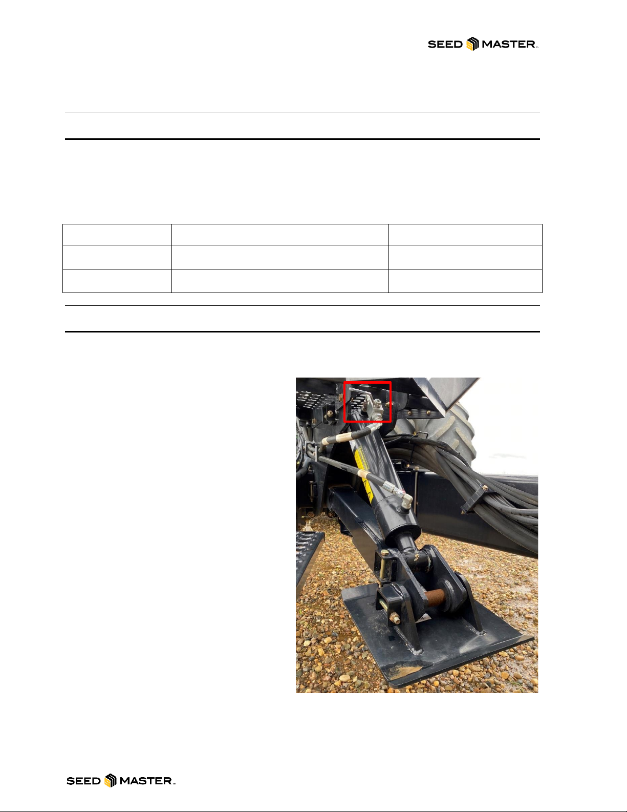
HYDRAULIC JACK
To increase the ease of hooking your tractor to the Ultra SR, it has been equipped with a hydraulic jack.
To use:
1. Couple the hydraulic hoses with white
tags to your tractor.
2. Open the manual shut-off valve located
on the hydraulic jack and use your
tractor hydraulics to lift and lower the
tongue into place on your receiver.
3. Once connected, ensure that you lift the
jack all the way to the top to ensure that
it will clear any obstacles encountered
during seeder use.
4. When detaching the jack’s hydraulic
hoses, confirm that the manual shut-off
valve is closed first.
5. When uncoupling the Ultra SR from
your tractor, make sure that there is
adequate blocking under the foot of the
jack as well as behind the tires. This will
help secure the machine from any
movement or potential sinking in softer
ground.
LOAD STATUS
MACHINE WEIGHT (LBS)
TONGUE WEIGHT (LBS)
UNLOADED
~45,000
~2,800
LOADED
~97,000
~15,000

SEEDMASTER 2023
10
TRANSPORT
To help ensure the Residue Management System and openers have adequate clearance during
transport, the Ultra SR’s rank height adjustment raises to its highest position automatically when you
raise the machine’s openers. To alleviate some of the extreme forces of transport on the cylinders, it is
required to install the supplied cylinder stops whenever you are transporting the machine.
NOTE: DO NOT transport the machine on roadways or faster than 6 mph when fully
loaded. Damage of this nature is NOT covered by warranty.
1. Raise the openers fully. Ensure the system pressure is disengaged before proceeding.
2. Locate the cylinder stops hanging on the backside of the rear axle.
3. Remove the retaining pins.
4. Mount the cylinder stop on the fully extended rank height cylinder.
5. Reinstall the retaining pins.
6. Due to the forces incurred during transport, it is a good practice to provide very brief pressure to
the system pressure circuit to facilitate the removal of the cylinder stops. Ensure the system
pressure is disengaged before proceeding.
7. Ensure that the cylinder pivot points are greased every 20 hours of use.
SEEDMASTER 2023
11
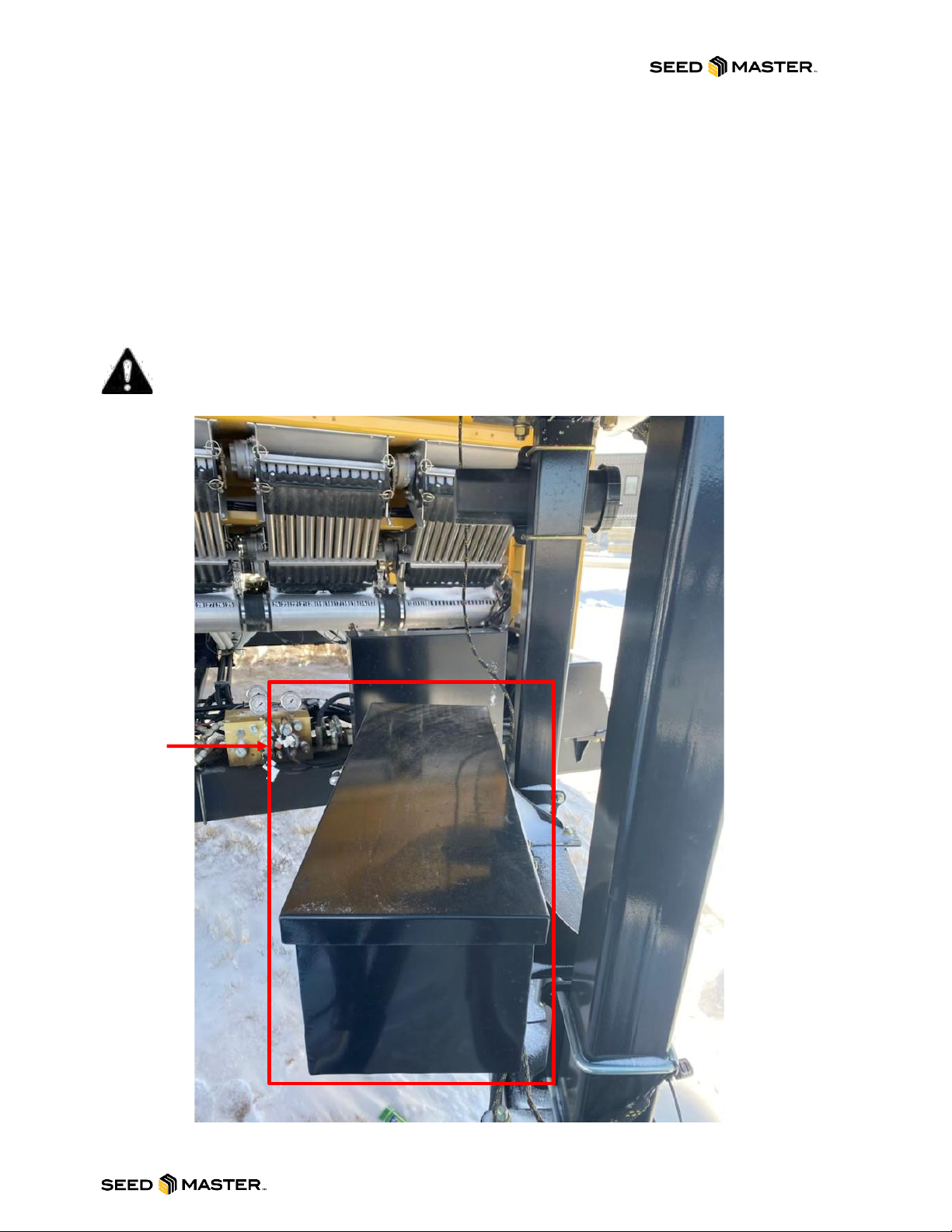
TOOLBOX
SeedMaster offers a factory option toolbox to hold any spare parts, tools, or accessories to keep your
seeding operation moving. It is located on the left support leg of the front tank walkway. The toolbox has
a seal to help reduce the amount of dust and foreign material from contaminating or soiling the contents.
Above the toolbox is a container that contains your machine-specific manuals. This container is dust
and water tight to ensure that your manuals stay intact in any weather or field conditions.
For machines with tow-between distribution, or a front-mounted tank, the toolbox will be located at the
top of the “A-frame” beside the main-frame castor.
NOTE: Do not stand or walk on the toolbox!
TOOLBOX

SEEDMASTER 2023
12
IN-CAB ELECTRICAL HOOKUP
RAVEN VIPER 4+ IN-CAB HOOKUP
SLINGSHOT POWER
GPS IN
SWITCHED POWER OUTPUT
ISOBUS DIAGNOSTICS PORT
RAVEN CANBUS
ISOBUS TERMINATOR
NOT USED
NOT USED
NOT USED
BATTERY CONNECTIONS

SEEDMASTER 2023
13
ELECTRICAL HOOKUPS
There are three electrical hookups required when attaching the Seeder. The IBBC connector (Image 1),
the High Current Auxiliary connection (Image 2), and Implement Master Switch (Image 3).
Image 3
Image 1
Image 2

SEEDMASTER 2023
14
TRACTOR HYDRAULIC HOOKUPS
SEEDMASTER ULTRA SR HYDRAULIC HOSES
HOSE MARKING CONVENTION: Each hose pair has been assigned a unique colour. The hose with 1
colour band is pressure, and the hose with 2 colour bands is return.
OPENER RAISE/LOWER HOSES: Red Tagged Lines –The two ½” Direct Opener Lift & Lower
hydraulic lines with red colour bands are the opener lift and lower lines. These lines are connected to
one tractor remote. The hose with 1 red band is opener down pressure. The hose with 2 red bands is
pressurized to raise the openers. The openers are held up in transport with a Pilot Operated Check
Valve. This maintains the pressure on the opener up pressure circuit for long transport and to facilitate
unhooking under lift pressure. Leave the pressure engaged to operate the Smart Openers.NOTE: See
page 19 for operation instructions.
SYSTEM PRESSURE HOSES: Green Tagged Lines –The two ½” hydraulic lines with the green colour
bands are used to activate the block and raise and lower the wings. These lines are connected to one
tractor remote. In the field, operating position for this remote is locked-on to provide continuous pressure
to the block via the line with 1 green band. Pressure should be adjusted and set between 2600-3000 psi
by using the tractor remote flow control.
HYDRAULIC JACK HOSES: White Tagged Lines –The two ½” hydraulic lines with the white colour
bands are used to activate the hydraulic jack to raise and lower the machine into place to connect a
tractor. These lines are connected to one tractor remote. The manual valve is used to lock the jack up or
down and to facilitate unhooking under pressure. Open the valve after hooking hydraulics to tractor. See
page 9 for operation instructions.
SEED AND FERT FAN HOSES: There will be two ¾” fan pairs. The seed fan hoses will be tagged with
1x orange (pressure) and 2x orange (return) and the fertilizer fan will be tagged with 1x purple
(pressure) and 2x purple (return).
Ensure that you connect the right pair of hoses together on your tractor.
CASE DRAIN HOSE: Drills and tanks are set up with ONE 1/2" case drain/return line (zero back
pressure). This line has a ½” NPT full open return coupler without any restriction or back pressure.
Ensure this return line is routed to your tractor properly without any possibility of back pressure.
Improper connection or undersized return lines on the tractor may cause inaccuracies in operation and
the possibility for severe damage to the drill’s hydraulic system. SeedMaster Manufacturing
recommends using the factory connections provided with the drill and tank.
SEEDMASTER 2023
15
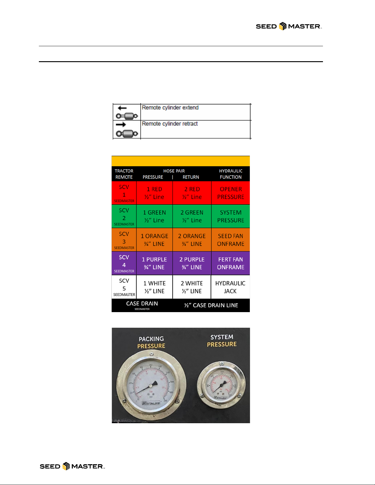
HYDRAULIC CONNECTION REFERENCE CARDS
The Ultra SR’s hydraulic hookup reference card is below. Ensure that you are hooking the pressure and
return hoses to the appropriate remotes on your tractor: Pressure to Retract, Return to Extend. The
main hydraulic pressure gauges have been mounted at the hitch to increase visibility.
Ultra SR Hydraulic Hookup

SEEDMASTER 2023
16
MAIN HYDRAULIC BLOCK DETAILS
HYDRAULIC BLOCK GAUGES
MAIN BLOCK GAUGES
WING UP: The WING UP gauge reads the amount of pressure applied and required for lifting and
should read 0 psi until folding up. A positive reading during field operation is an indication of back
pressure on the system.
TANK: The TANK gauge reads the amount of pressure being returned to tank.
WING DOWN: The WING DOWN gauge reads the amount psi being applied to the wings while they are
down and in field operation.
SYS: As shown on Page 15, the SYS gauge is now mounted at the hitch for easier viewing. It reads the
amount of system pressure being applied to the system. System Pressure is the main pressure supply
for the WING UP/DN circuits. 2600-3000 psi indicates tractor working pressure to block. Pressure
fluctuation can indicate back pressure or lack of flow to the circuit. Adjust tractor flow as necessary to
hold within that range
WING DOWN
TANK
SYSTEM PRESSURE
(HITCH MOUNTED)
WING UP
SEEDMASTER 2023
17
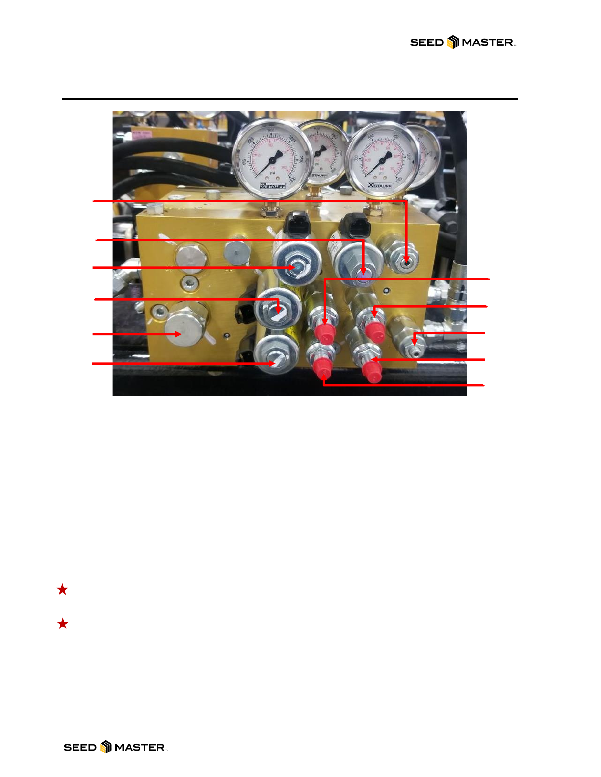
MAIN BLOCK VALVES, SOLENOIDS, AND PWMS
LEFT WING LOCK: This on/off solenoid turns the oil flow on/off to the left wing cylinders.
RIGHT WING LOCK: This on/off solenoid turns the oil flow on/off to the right wing cylinders.
OUTER WING LOCK: This on/off solenoid turns the oil flow on/off to the outer wing cylinders.
FAST WING: This on/off solenoid turns the oil flow on/off to the inner wing cylinders.
HIGH PRESSURE WING RELIEF (THERMAL): High tank pressure cut off cartridge is preset set at
3500 psi
TANK LINE RELIEF: The tank line relief cartridge is preset at 450 psi. If the cartridge exceeds 450 psi it
will relieve to the atmosphere.
WING-DOWN PRESSURE: 150 psi (NOTE: NEVER EXCEED THE RECOMMENDED NET WING
DOWN PRESSURE. A HIGHER PRESSURE CAN INTRODUCE THE POTENTIAL FOR THE WINGS
TO UNFOLD UNEXPECTEDLY. SEE PAGE 14 FOR SETTING PROCEDURE).
Wing-Down pressure may need to be increased if the wings start to float and not contour
correctly while in the seeding position or if a positive Wing-Up pressure is detected.
Wing-Down pressure may need to be decreased if the wings become too rigid while in the
seeding position.
FAST WING PRESSURE: 1500 psi
SAFETY SHIFT VALVE: The safety shift valve will shut the hydraulic flow off to the block if back
pressure reaches 240 psi on tank line to prevent system damage.
HIGH
PRESSURE
WING RELIEF
(THERMAL)
OUTER WING
LOCK
LEFT WING
LOCK
RIGHT WING
LOCK
FAST WING
WING DOWN
PRESSURE
TANK LINE
RELIEF
FAST WING
PRESSURE
LIFT KIT
RAVEN (METER)
SUPPLY (NOT USED)
SAFETY SHIFT
VALVE
SEEDMASTER 2023
18
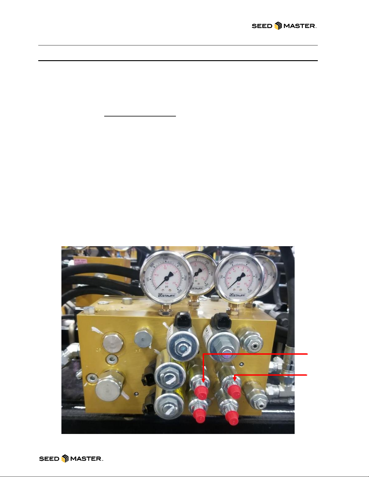
PRESSURE SETTING PROCEDURES
Setting Wing-Down Procedure (WING-DOWN PRESSURE)
The Wing-Down pressure is the amount of hydraulic pressure being applied to the inner and outer wing
circuits; the oil supply is supplied from the system pressure. The Wing-Down Pressure is required so the
wings will contour while travelling through the field.
The Ultra SR requires a Net Wing-Down Pressure of 150 PSI. To determine your net value, ensure
your system pressure and fans are running and subtract your wing-up pressure from your current wing-
down pressure (ie. 350 PSI wing-down –200 PSI wing-up = 150 PSI net wing-down).
-To adjust the WING-DOWN PRESSURE, loosen the jam nut on the cartridge in port WD on the
main block. Turn the cartridge in to increase the pressure, and out to decrease the pressure.
When the desired pressure is set, re-tighten the jam nut.
Setting Wing Unfold Procedure (FAST WING PRESSURE)
The wing unfold pressure is the amount of hydraulic pressure being applied to the inner and outer wing
circuits while the tool bar is unfolding. This is also known as the Fast-Wing Pressure. If the wings are
not unfolding the pressure will need to be increased. The oil supply is supplied from the system
pressure.
-To adjust the FAST-WING PRESSURE, loosen the jam nut on the cartridge in port FW PRESS
on the main block. Turn the cartridge in to increase the pressure and out to decrease the
pressure. When the desired pressure is set, re-tighten the jam nut.
FAST WING
PRESSURE
WING DOWN
PRESSURE

SEEDMASTER 2023
19
SMART OPENERS HYDRAULIC BLOCK DETAILS
AND OPERATION
SMART OPENERS HYDRAULIC BLOCK
The Smart Openers block contains the main functions of your Ultra SR openers: raising, lowering, and
down-pressure. These functions are controlled by a Master ON/OFF solenoid and coil to raise and
lower, and a PWM valve for down-pressure. The Smart Openers block is located on the frame rail under
Tank 1. For it to operate, you will leave the connected tractor hydraulic remote engaged during field
operation. Recommended maximum flow for this remote is 75%.
SMART OPENER OPERATION
LOWER, LIFTING, THEN LOWERING THE OPENERS
LOWER:
1. LOCK ON REMOTE TO SUPPLY OPENERS WITH HYDRAULIC PRESSURE.
2. CYCLE MASTER FOOT SWITCH FROM OFF TO ON AND LEAVE THE MASTER SWITCH
“ON”. OPENERS WILL LOWER AND BUILD PRESSURE TO YOUR PRESET VALUE.
LIFT:
3. AFTER THE TOOLBAR IS COMPLETEY OVERLAPPED INTO AN APPLIED AREA, SHUT
THE MASTER FOOT SWITCH OFF. OPENERS WILL LIFT.
4. COMPLETE THE TURN.
LOWER:
5. CYCLE MASTER FOOT SWITCH FROM OFF TO ON AND LEAVE THE MASTER SWITCH
“ON” OPENERS WILL LOWER AND BUILD PRESSURE TO YOUR PRESET VALUE.
Table of contents
Other SEEDMASTER Farm Equipment manuals


