Seeed Grove Beginner Kit User manual

Grove Beginner Kit For Arduino®
User Manual

Grove Beginner Kit for Arduino is one of the best Arduino Beginner Kit for beginners. It includes
one Arduino compatible Board and 10 additional Arduino sensors and all in one-piece of PCB
design. All the modules have been connected to the Seeeduino through the PCB stamp
holes so no Grove cables are needed to connect. Of course, you can also take the modules
out and use Grove cables to connect the modules. You can build any Arduino project you like
with this Grove Beginner Kit For Arduino.
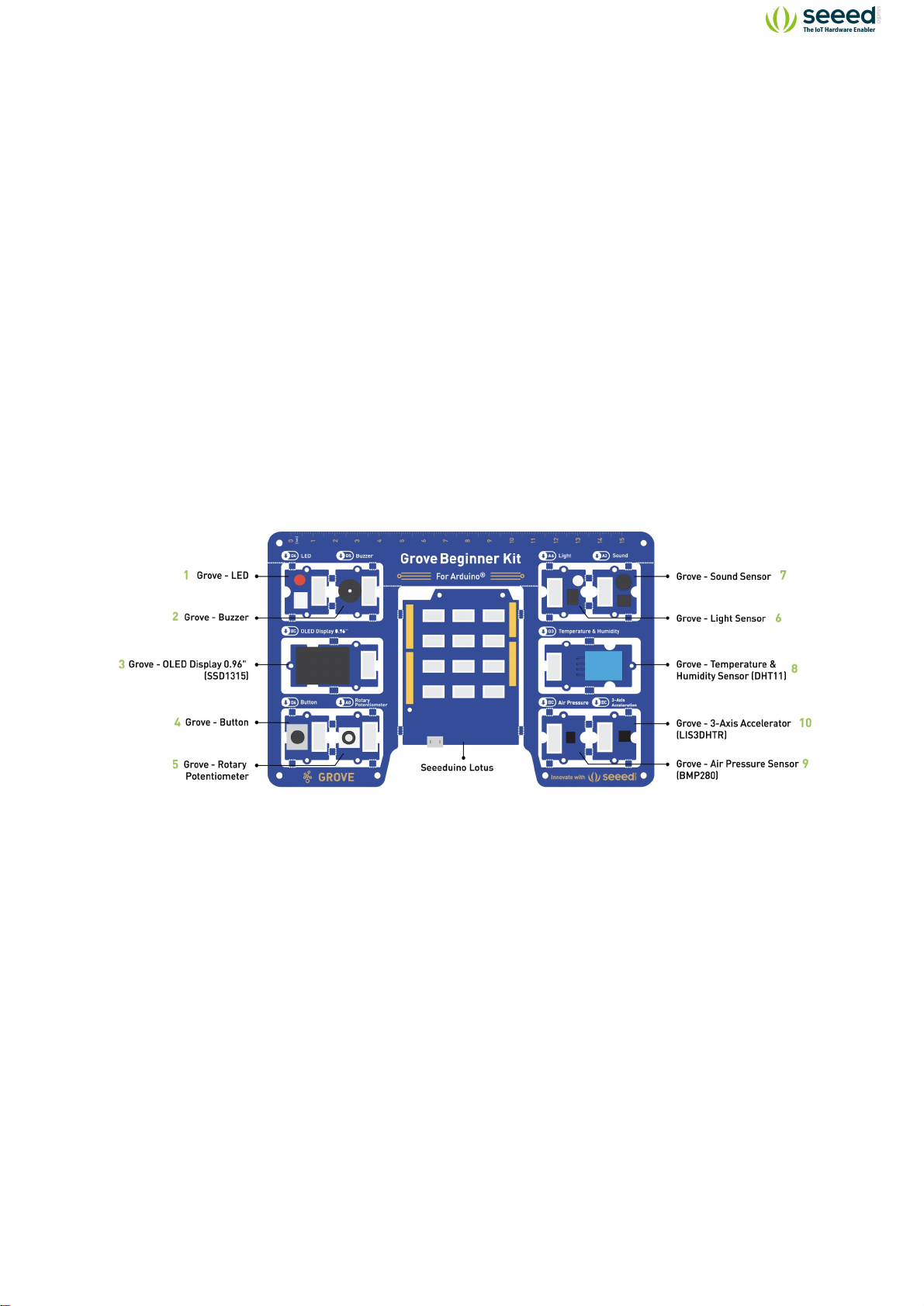
Hardware Overview
Note: Dimensions - 17.69 * 11.64 * 1.88cm
1. Grove - LED: Simple LED module
2. Grove - Buzzer: Piezo Buzzer
3. Grove - OLED Display 0.96”: 128×64 dot resolution High brightness,self-emission and high
contrast ratio Big screen on a compact design Low power consumption.
4. Grove - Button: Push button for human input interfaces
5. Grove - Rotary Potentiometer: Rotary knob for human input interfaces
6. Grove - Light: Detects surrounding light intensity
7. Grove - Sound: Detects surrounding sound intensity
8. Grove - Temperature & Humidity Sensor: Detects surrounding temperature and humidity
values
9. Grove - Air Pressure Sensor: Detects surrounding atmospheric pressure
10. Grove - 3-Axis Accelerator: Detects object acceleration
11. Seeeduino Lotus: Arduino Compatible Board with Grove Ports
1
Grove Beginner Kit For Arduino®
Grove Beginner Kit For
Arduino®

2
70 …………… Tech Support
Index
Grove Beginner Kit For Arduino®
1…………….. Harware Overview
4…………….. Part List
5…………….. Learning Objectives
6…………….. How To Get Started With Arduino
10 ...…………. Lesson 1: Blinking with the LED
15 …………… Lesson 2: Pressing Button to Light Up LED
20 …………… Lesson 3: Controlling the Speed of the Blink
24 …………… Lesson 4: Making the Buzzer go BEEP
28 …………… Lesson 5: Making an Light Induct LED
35 …………… Lesson 6: Sound Sensitive LED Light
41 …………… Lesson 7: Displaying Data on OLED
47 …………… Lesson 8: Detecting Temperature &Humidity
51 …………… Lesson 9: Measuring Air Pressure
55 …………… Lesson 10: Sensing Movement
60 …………… Project 1: Music Dynamic Rhythm Lamp
64 …………… Project 2: Sound-Light Induction Lamp
69 …………… Resources
70 …………… More Learning

Note:
By default, Grove modules are connected to Seeeduino via PCB stamp holes. This means you
don’t need to use Grove cables to connect if not broken out. The default pins are as follow:
Modules Interface Pins/Address
LED Digital D4
Buzzer Digital D5
OLED Display 0.96” I2C I2C, 0x78(default)
Button Digital D6
Rotary Potentiometer Analog A0
Light Analog A6
Sound Analog A2
Temperature & Humidity Sensor Digital D3
Air Pressure Sensor I2C I2C, 0x77(default) / 0x76(optional)
3-Axis Accelerator I2C I2C, 0x63(default)
Breakout Instruction
Attention:
Please be careful not to cut your hands when using a knife
If you prefer to use the modules in elsewhere then you can simply follow the procedures to break
the modules out!
Step 1
Use a knife or a sharp object to cut at the stamp holes that connect the sensors together
Step 2
Shake the modules up and down and it should come out quite easily!
3
Grove Beginner Kit For Arduino®

Part List
Modules Quantity
Sensors
Temperature & Humidity Sensors x1
3-Axis Accelerometers x1
Air Pressure x1
Light Sensor x1
Sound Sensor x1
Input Modules
Rotary Potentiometer x1
Button x1
Output Modules
LED x1
Buzzer x1
Display Module
OLED Display x1
Grove Cables x6
Micro USB Cable x1
4
Grove Beginner Kit For Arduino®

Learning Objectives
Basics of Open Source Hardware Systems.
Basic Arduino Programming.
Communication principles and methods for sensors.
Hands-on implementation of Open Source Hardware projects.
Plug and Play Unboxing Demo
The Grove Beginner Kit has a plug and plays unboxing demo, where you first plug in the power to
the board, you get the chance to experience all the sensors in one go! Use the button and rotary
potentiometer to experience each sensor demo!
Scroll -> Rotating Rotary Potentiometer
Select -> Short Press Button
Exit Current Demo -> Long Press Button
Buzzer and LED module are used for key prompt.
5
Grove Beginner Kit For Arduino®

How to Get Started With Arduino
Install the Arduino IDE
Arduino IDE is an integrated development environment for Arduino, which is used for single-
chip microcomputer software programming, downloading, testing and so on.
Download and Install Arduino IDE for your desired operating system here.
Install the USB driver
Arduino connects to the PC via a USB cable. The USB driver depends on the type of USB
chip you’re using on your Arduino. Note: USB chips are usually printed on the back of the
development board.
Download the CP2102 USB Driver. Note: Download according to your OS.
After the driver installation is completed, connect Arduino to the USB port of PC with a
USB cable.
For Windows users: You can see it in My Computer -> Properties -> Hardware ->
Device Management . A COM will appear.
For Mac OS users: You can navigate to on the top left corner, and choose About
this Mac -> System Report... -> USB . A CP2102 USB Driver should appear.
If the driver is not installed, or if the driver is installed incorrectly (not matching the chip
model), it will appear as an “unknown device” in the device manager. At this point, the
driver should be reinstalled.
6
Grove Beginner Kit For Arduino®

Start the Arduino IDE
1. Open the Arduino IDE on your PC.
2. Click on Tools -> Board to select the correct Development Board Model. Select
Arduino/Genuino Uno as Board.
3. Click Tools -> Port to select the correct Port (the Serial Port showed in Device Manager
in the previous step). In this case, COM6 is selected. For Mac OS users, it should be
/dev/cu.SLAB_USBtoUART .
7
Grove Beginner Kit For Arduino®

1. Create a new Arduino file and name it Hello.ino , then copy the following code into it:
void setup() {
Serial.begin(9600); // initializes the serial port with a baud rate of
9600
}
void loop() {
Serial.println("hello, world"); // prints a string to a serial port
delay(1000); //delay of 1 second
}
5. In the upper left corner of the Arduino IDE, there are two buttons, Verify and Upload. First,
press the Verify button(✓) to compile. After the compilation is successful, press the upload
button(→).
6. Navigate to Tools -> Serial Monitor , or click the Serial Monitor in the upper right
corner(Magnifier Symbol), you can see the program running results:
Note: If you installed the portable Arduino IDE from our USB Drive, you can find all the module
demos in the Files -> Sketch Book, as well as all the module libraries, are pre-installed with
Arduino IDE!
8
Grove Beginner Kit For Arduino®

Note:
All modules are pre-wired on a single circuit board, so no cables and soldering are needed.
However, if you break out the modules and want to connect them with Grove cables, please
kindly check the Breakout Guide.
9
Grove Beginner Kit For Arduino®

Lesson Guide
Lesson 1: Blinking with the LED
We have completed the output “Hello world” program. Now let’s learn how to light the LED
module. We know the three basic components of a control system: Input, Control, and Output.
But lighting up LED uses only the output, not the input. Seeeduino is the control unit, the LED
module is the output unit and the output signal is a digital signal.
Background Information:
What is Digital Signal
Digital signal: Digital signal refers to the value of the amplitude is discrete, the amplitude is
limited to a finite number of values. In our controller, the digital signal has two states: LOW(0V) for
0; HIGH(5V) for 1. So sending a HIGH signal to LED can light it up.
Components Involved
1. Seeeduino Lotus
2. Grove LED
3. Grove Cable(If Broken out)
10
Grove Beginner Kit For Arduino®

Hardware connection
Module connection
Default connection by PCB stamp hole.
Connect the Seeeduino to the computer through the USB cable.
Software Code
Open Arduino IDE.
Copy the following code, click Verify to check for syntax errors. Verify that there are no
errors, and you can upload the code.
//LED Blink
//The LED will turn on for one second and then turn off for one second
int ledPin = 4;
void setup() {
pinMode(ledPin, OUTPUT);
}
void loop() {
digitalWrite(ledPin, HIGH);
delay(1000);
digitalWrite(ledPin, LOW);
delay(1000);
}
11
Grove Beginner Kit For Arduino®

Code Analysis
setup(){
}
The setup() function is called when a sketch starts. Use it to initialize variables, pin modes,
start using libraries, etc. The setup() function will only run once, after each powerup or reset of
the Arduino board.
loop(){
}
After creating a setup() function, which initializes and sets the initial values, the loop()
function does precisely what its name suggests, and loops consecutively, allowing your program
to change and respond. Use it to actively control the Arduino board.
int ledPin = 4;
Description:
Converts a value to the int data type.
Syntax:
int(x) or (int)x (C-style type conversion)
Parameters:
x: a value. Allowed data types: any type.
Assigned an int type 4 to variable named ledPin.
pinMode(ledPin, OUTPUT);
Description:
Configures the specified pin to behave either as an input or an output. See the Digital Pins page
for details on the functionality of the pins.
As of Arduino 1.0.1, it is possible to enable the internal pull-up resistors with the mode
INPUT_PULLUP . Additionally, the INPUT mode explicitly disables the internal pullups.
Syntax:
pinMode(pin, mode)
Parameters:
12
Grove Beginner Kit For Arduino®

pin: the Arduino pin number to set the mode of.
mode: INPUT , OUTPUT , or INPUT_PULLUP .
Setting ledPin to the output mode.
digitalWrite(ledPin, HIGH);
Description:
Write a HIGH or a LOW value to a digital pin.
If the pin has been configured as an OUTPUT with pinMode(), its voltage will be set to the
corresponding value: 5V (or 3.3V on 3.3V boards) for HIGH , 0V (ground) for LOW .
If the pin is configured as an INPUT, digitalWrite() will enable (HIGH) or disable (LOW) the internal
pullup on the input pin. It is recommended to set the pinMode() to INPUT_PULLUP to enable the
internal pull-up resistor. See the Digital Pins tutorial for more information.
If you do not set the pinMode() to OUTPUT, and connect an LED to a pin, when calling
digitalWrite(HIGH), the LED may appear dim. Without explicitly setting pinMode(), digitalWrite()
will have enabled the internal pull-up resistor, which acts as a large current-limiting resistor.
Syntax:
digitalWrite(pin, value)
Parameters:
pin: the Arduino pin number.
value: HIGH or LOW .
When we set the ledPin as output, HIGH means sending high level to the pin, LED turns on.
digitalWrite(ledPin, LOW);
When we set the led as output, low stands for sending low level to the pin, LED turns off.
delay(1000);
Description:
Pauses the program for the amount of time (in milliseconds) specified as a parameter. (There are
1000 milliseconds in a second.)
Syntax:
delay(ms)
13
Grove Beginner Kit For Arduino®

Parameters:
ms: the number of milliseconds to pause. Allowed data types: unsigned long.
Delay the program by 1000ms(1s).
Demo Effect and Serial Print Result:
The LED module will be 1 second on and 1 second off.
Breakout Guide
If modules are broken out from the board. Use a Grove cable to connect the Grove LED to
Seeeduino Lotus’s digital interface D4.
14
Grove Beginner Kit For Arduino®

Lesson 2: Pressing Button to Light Up LED
The first thing we need to know is that the input of the button is a digital signal, and there are only
two states, 0 or 1, so we can control the output based on those two states.
Practice: Use button to turn ON and OFF the LED module
Components Involved
1. Seeeduino Lotus
2. Grove LED
3. Grove Button
4. Grove Cables(If broken out)
Hardware connection
Module connection:
Default connection by PCB stamp hole.
The Seeeduino is then connected to the computer via a USB cable.
Hardware analysis:
Input: Button
Control: Seeeduino
15
Grove Beginner Kit For Arduino®

Output: LED module
Both the sensor and the LED use digital signals, so they should be connected to digital
interfaces.
Software code:
Open Arduino IDE.
Copy the following code, click Verify to check for syntax errors. Verify that there are no
errors, and you can upload the code.
//Button to turn ON/OFF LED
//Constants won't change. They're used here to set pin numbers:
const int buttonPin = 6; // the number of the pushbutton pin
const int ledPin = 4; // the number of the LED pin
// variables will change:
int buttonState = 0; // variable for reading the pushbutton statu
s
void setup() {
// initialize the LED pin as an output:
pinMode(ledPin, OUTPUT);
// initialize the pushbutton pin as an input:
pinMode(buttonPin, INPUT);
}
void loop() {
// read the state of the pushbutton value:
buttonState = digitalRead(buttonPin);
// check if the pushbutton is pressed. If it is, the buttonState is HIG
H:
if (buttonState == HIGH) {
// turn LED on:
digitalWrite(ledPin, HIGH);
} else {
// turn LED off:
digitalWrite(ledPin, LOW);
}
}
16
Grove Beginner Kit For Arduino®

Code Analysis
pinMode(ledPin, OUTPUT);
Define LED as the output unit.
pinMode(buttonPin, INPUT);
Define button as the input unit.
17
Grove Beginner Kit For Arduino®

buttonState = digitalRead(buttonPin);
Description:
Reads the value from a specified digital pin, either HIGH or LOW .
Syntax:
digitalRead(pin)
Parameters:
pin: the Arduino pin number you want to read
This function is used to read the states of digital pins, either HIGH or LOW. When the button is
pressed, the state is HIGH, otherwise is LOW.
if (buttonState == HIGH) {
digitalWrite(ledPin, HIGH);
} else {
digitalWrite(ledPin, LOW);
}
}
Description:
The if…else allows greater control over the flow of code than the basic if statement, by allowing
multiple tests to be grouped. An else clause (if at all exists) will be executed if the condition in the
if statement results in false. The else can proceed another if test, so that multiple, mutually
exclusive tests can be run at the same time.
Each test will proceed to the next one until a true test is encountered. When a true test is found,
its associated block of code is run, and the program then skips to the line following the entire
if/else construction. If no test proves to be true, the default else block is executed, if one is
present, and sets the default behaviour.
Note that an else if block may be used with or without a terminating else block and vice versa. An
unlimited number of such else if branches are allowed.
18
Grove Beginner Kit For Arduino®

Syntax:
if (condition1) {
// do Thing A
}
else if (condition2) {
// do Thing B
}
else {
// do Thing C
}
The usage of the statement is: if the logical expression in parentheses is true, execute the
statement in curly braces after if, if not, execute the statement in curly braces after the else. If
the state of the button is high, the LED pin outputs a high level and turn the LED on, else turn
LED off.
Demo Effect and Serial Print Result:
Pressing the button will turn the LED module on.
Breakout Guide
Use a Grove cable to connect the Grove LED to Seeeduino Lotus’s digital interface D4. Connect
the Grove Button to digital interface D6.
19
Grove Beginner Kit For Arduino®
Other manuals for Grove Beginner Kit
1
Table of contents
Other Seeed Motherboard manuals