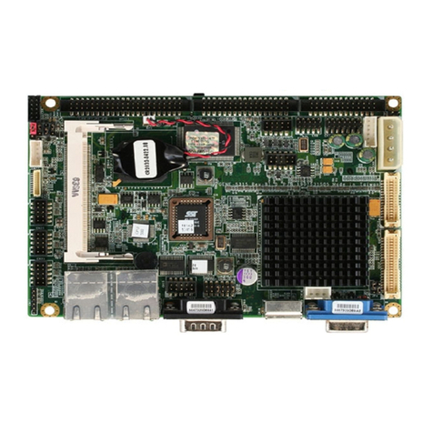
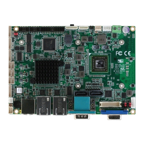
Aaeon PCM-6890 User manual

PCM-6890PCM-6890
PCM-6890PCM-6890
PCM-6890
All-in-One Socket 370 Celeron
Single Board Computer with
LCD, Ethernet, Audio, & 4 COMs

FCC STATEMENT
THISDEVICECOMPLIESWITHPART15FCCRULES.
OPERATIONISSUBJECTTO THEFOLLOWINGTWO
CONDITIONS:(1)THISDEVICEMAYNOTCAUSEHARM-
FULINTERFERENCE.(2)THISDEVICEMUSTACCEPTANY
INTERFERENCERECEIVEDINCLUDINGINTERFERENCE
THATMAYCAUSE UNDESIRED OPERATION.
THIS EQUIPMENT HAS BEEN TESTED AND FOUND TO
COMPLY WITH THE LIMITS FOR A CLASS "A" DIGITAL
DEVICE, PURSUANT TO PART 15 OF THE FCC RULES.
THESE LIMITS ARE DESIGNED TO PROVIDE REASON-
ABLE PROTECTION AGAINTST HARMFUL INTERFER-
ENCEWHEN THE EQUIPMENT IS OPERATED IN A
COMMERCIAL ENVIRONMENT. THIS EQUIPMENT
GENERATES,USES, AND CAN RADIATE RADIO FRE-
QUENCY ENERGYAND, IFNOTINSTATLLEDANDUSED
IN ACCORDANCEWITH THE INSTRUCTION MANUAL,
MAY CAUSE HARMFUL INTERFERENCE TO RADIO
COMMUNICATIONS.OPERATION OF THIS EQUIPMENT
IN A RESIDENTIALAREA IS LIKELY TO CAUSE HARM-
FUL INTERFERENCE IN WHICH CASE THE USER WILL
BE REQUIRED TOCORRECT THE INTERFERENCE AT HIS
OWN EXPENSE.

Copyright NoticeCopyright Notice
Copyright Notice
This document is copyrighted, 1999. All rights are reserved. The
original manufacturer reserves the right to make improvements to
the products described in this manual at any time without notice.
No part of this manual may be reproduced, copied, translated, or
transmitted in any form or by any means without the prior written
permission of the original manufacturer. Information provided in
this manual is intended to be accurate and reliable. However, the
original manufacturer assumes no responsibility for its use, nor for
any infringements upon the rights of third parties which may result
from its use.
AcknowledgementsAcknowledgements
Acknowledgements
AMD is a trademark of Advanced Micro Devices, Inc.
AMI is a trademark of American Megatrends, Inc.
Award is a trademark of Award Software International, Inc.
Cyrixisa trademark ofCyrixCorporation.
IBM, PC/AT, PS/2, and VGA are trademarks of International
Business Machines Corporation.
Intel and Pentium II are trademarks of Intel Corporation.
Microsoft Windows ®is a registered trademark of Microsoft Corp.
SMC is a trademark of Standard Microsystems Corporation.
RTLis a trademarkof Realtek Semi-ConductorCo., Ltd.
C&T is a trademark of Chips and Technologies, Inc.
UMC is a trademark of United Microelectronics Corporation.
ITE is a trademark of Integrated Technology Express, Inc.
SiS is a trademark of Silicon Integrated Systems Corp.
VIA is a trademark of VIA Technology, Inc.
All other product names or trademarks are properties of their
respective owners.
PartNo.2047689003 Manual PCM-6890 4rd Edition
Prepared in Taiwan Dec. 2001

A Message to the CustomerA Message to the Customer
A Message to the Customer
AAEON Customer ServicesAAEON Customer Services
AAEON Customer Services
Each and every AAEON product is built to the most exacting
specifications to ensure reliable performance in the harsh and
demanding conditions typical of industrial environments. Whether
your new AAEON equipment is destined for the laboratory or the
factory floor, you can be assured that your product will provide the
reliability and ease of operation for which the name AAEON has
come to be known.
Your satisfaction is our primary concern. Here is a guide to
AAEON’s customer services. To ensure you get the full benefit of
our services, please follow the instructions below carefully.
Technical SupportTechnical Support
Technical Support
We want you to get the maximum performance from your products.
So if you run into technical difficulties, we are here to help. For the
most frequently asked questions, you can easily find answers in
your product documentation. These answers are normally a lot
more detailed than the ones we can give over the phone.
So please consult this manual first. If you still cannot find the
answer, gather all the information or questions that apply to your
problem, and with the product close at hand, call your dealer. Our
dealers are well trained and ready to give you the support you need
to get the most from your AAEON products. In fact, most problems
reported are minor and are able to be easily solved over the phone.
In addition, free technical support is available from AAEON
engineers every business day. We are always ready to give advice
on application requirements or specific information on the installa-
tion and operation of any of our products.

Product WarrantyProduct Warranty
Product Warranty
AAEON warrants to you, the original purchaser, that each of its
products will be free from defects in materials and workmanship for
one year from the date of purchase.
This warranty does not apply to any products which have been
repaired or altered by persons other than repair personnel autho-
rized by AAEON, or which have been subject to misuse, abuse,
accident or improper installation. AAEON assumes no liability
under the terms of this warranty as a consequence of such events.
Because of AAEON’s high quality-control standards and rigorous
testing, most of our customers never need to use our repair service.
If an AAEON product is defective, it will be repaired or replaced at
no charge during the warranty period. For out-of-warranty repairs,
you will be billed according to the cost of replacement materials,
service time, and freight. Please consult your dealer for more
details.
If you think you have a defective product, follow these steps:
1. Collect all the information about the problem encountered. (For
example, CPU type and speed, AAEON products used, other
hardware and software used, etc.) Note anything abnormal and
list any on-screen messages you get when the problem occurs.
2. Call your dealer and describe the problem. Please have your
manual, product, and any helpful information readily available.
3. If your product is diagnosed as defective, obtain an RMA
(return material authorization) number from your dealer. This
allows us to process your return more quickly.
4. Carefully pack the defective product, a fully-completed Repair
and Replacement Order Card and a photocopy proof of pur-
chase date (such as your sales receipt) in a shippable container.
A product returned without proof of the purchase date is not
eligible for warranty service.
5. Write the RMA number visibly on the outside of the package
and ship it prepaid to your dealer.

Packing listPacking list
Packing list
Before you begin installing your card, please make sure that the
following materials have been shipped:
• 1PCM-6890All-in-OneSingle Board Computer
• 1Quick InstallationGuide
• 1 CD-ROM contains the followings:
—User’ s Manual (this manual in PDF file)
— Ethernet drivers and utilities
— VGA drivers and utilities
— Audio drivers and utilities
— Lastest BIOS (as of the CD-ROM was made)
The PCM-6890 require several cables for operation. You can make
them yourself or pruchase an optioanl cable kit, PCM-10489-4 (P/N :
9979048910).
If any of these items are missing or damaged, contact your distri-
butor or sales representative immediately.

NoticeNotice
NoticeNotice
Notice
DearCustomer,
Thank you for purchasing the PCM-6890 board. This user’s manual
is designed to help you to get the most out of the PCM-6890,
please read it thoroughly before you install and use the board. The
product that you have purchased comes with an two-year limited
warranty, but AAEON will not be responsible for misuse of the
product. Therefore, we strongly urge you to first read the manual
before using the product.
To receive the lastest version of the user manual, please visit our
Web site at:
http://www.aaeon.com

ContentsContents
ContentsContents
Contents
Chapter 1: General Information.......................1Chapter 1: General Information.......................1
Chapter 1: General Information.......................1
Introduction ... ................................................................. 2
Features.................................................................................. 3
Specifications ......................................................................... 4
Board layout ........................................................................... 7
Board dimensions ................................................................. 8
Chapter 2: InstallaionChapter 2: Installaion
Chapter 2: Installaion ................................................................................................
................................................................................................
................................................99
99
9
Jumpers and connectors.................................................... 10
Locating jumpers ................................................................ 12
Locating connectors ........................................................... 13
Setting jumpers ................................................................... 14
CPU installing and upgrading............................................ 15
Installing DRAM (DIMMs) .............................................. 16
Cache Memory .................................................................... 17
Clear CMOS (J1)................................................................ 18
System temperature thermal sensor (J2)........................ 18
COM3/COM4 RI pin voltage select (J3, J4) ................ 19
Audio output select (J5) .................................................... 20
ATX Soft-Power Switch connector (J6) ........................... 20
COM2 RS-232/422/485 select (J10, J7)......................... 21
LCD clock signal select (J8)............................................. 22
LCD driving voltage select (J9) ....................................... 22
Power connectors (CN9, CN1) ......................................... 23
USB connector (CN3)......................................................... 24
CD Audio connector (CN4) ............................................... 24
IDE hard drive connector (CN6) ...................................... 25
Front panel connector (CN7) ............................................ 27
IrDA connector (CN8) ....................................................... 28
Display connectors (CN10, CN12) ................................... 29
Keyboard and mouse connector (CN11) ......................... 31
Audio connector (CN13).................................................... 32

Parallel port connector (CN14)......................................... 33
100Base-Tx Ethernet connector (CN15)........................ 34
Serial ports (CN16)............................................................. 35
Floppy drive connector (CN17) ........................................ 36
SW1 (4~6) CPU frequency ratio........................................ 38
SW1 (2~3) DOC address select........................................ 39
Ethernet LED signal connectors (LED2)........................ 40
DiskOnChip socket (U18)................................................. 41
DiskOnChip (DOC) 2000 Installation ............................. 42
Chapter 3: Award BIOS SetupChapter 3: Award BIOS Setup
Chapter 3: Award BIOS Setup..............................................................
..............................................................
............................... 4343
4343
43
Starting setup....................................................................... 44
Setup keys............................................................................ 45
Getting help ......................................................................... 46
In case of problem...................................................................46
Main setup menu ................................................................ 47
Standard CMOS setup ....................................................... 49
BIOS features setup ........................................................... 56
CHIPSET features setup ................................................... 60
Powr management setup .................................................... 64
PNP/PCI configuration setup ............................................ 69
Load BIOS defaults/Load setup defaults ........................ 72
Integrated peripherals setup............................................. 73
Supervisor/User password setting ................................... 76
IDE HDD auto detection ................................................... 78
Save & exit setup................................................................ 79
Chapter 4: C&T 69000 Flat Panel/CRT controllerChapter 4: C&T 69000 Flat Panel/CRT controller
Chapter 4: C&T 69000 Flat Panel/CRT controller
Display Drivers and UtilitiesDisplay Drivers and Utilities
Display Drivers and Utilities ....................
....................
.......... 8181
8181
81
Software drives .................................................................... 82
Hardware configuration ..........................................................82
Necessary prerequisites ..........................................................83
Before you begin .....................................................................83

Windows 95 .......................................................................... 84
Driverinstallation ....................................................................84
Windows 3.1......................................................................... 92
Driverinstallation ....................................................................92
OS/2....................................................................................... 93
Windows NT 3.51................................................................ 95
Driverinstallation ....................................................................95
Windows NT 4.0 .................................................................. 96
Driverinstallation ....................................................................96
Chapter 5: Ethernet Software Configuration...........................97
Ethernet software configuration ....................................... 98
Chapter 6: Audio SetupChapter 6: Audio Setup
Chapter 6: Audio Setup....................................................................................
....................................................................................
.......................................... 9999
9999
99
Introduction .......................................................................100
Setting Up in Windows 95................................................100
Installing the Drivers and the Application .............................101
Setting Up in NT 4.0 .........................................................103
Installing the Audio Drivers...................................................103
Driverinstallation ..................................................................103
Appendix A: Programming the WatchdogAppendix A: Programming the Watchdog
Appendix A: Programming the Watchdog
TimerTimer
TimerTimer
Timer....................................................................................................
....................................................................................................
.................................................. 105105
105105
105
Programming the watchdog timer ..................................106
Watchdog timer .....................................................................106
Configuration register ............................................................106
Appendix B: Installing PC/104 ModulesAppendix B: Installing PC/104 Modules
Appendix B: Installing PC/104 Modules....................
....................
.......... 113113
113113
113
Installing PC/104 modules............................................... 114
Appendix c: Optional ExtrasAppendix c: Optional Extras
Appendix c: Optional Extras..............................................................
..............................................................
............................... 117117
117117
117
PCM-10489-4 Wiring Kit ................................................120
Optional USB Cable..........................................................121
Chapter 1 General Information 1
1
General
Information
This chapter gives background informa-
tion on the mainboard.
Sections include:
• Board specifications
• Layout and dimensions
CHAPTER

2PCM-6890 User Manual
Introduction
The PCM-6890 is an all-in-one multi-media Celeron processor based
single board computer (SBC) with a 32-bit PCI audio controller, a
PCIFlat Panelcontroller,aPCI 100Base-Tx Ethernet interface, and
one PCI expansion slot. When using an Intel Pentium II processor,
the PCM-6890 achieves outstanding performance that surpasses
any other SBC in its class. In addition, the onboard SSD interface
supports M-systems DiskOnChip 2000 series, memory capacity
from 2 MB to 144 MB. This compact (only 5.75"“ x 8") unit offers
all the functions of a single board industrial computer, but still fits
in the space of a CD-ROM drive.
On-board features include four serial ports (three RS-232, one RS-
232/422/485),onemulti-modeparallel(ECP/EPP/SPP) port, connec-
tor for two USB (Universal Serial Bus) ports, a floppy drive
controller, and a keyboard/PS/2 mouse interface. The built-in high
speed PCI IDE controller supports Ultra DMA/33 mode. Up to two
IDE devices can be connected, including large hard disks, CD-
ROM drives, and tape backup drives, etc.
ThePCM-6890 alsofeatures power management to minimize power
consumption. It complies with the ACPI standard and supports
three types of power saving features: Doze mode, Standby mode,
and Suspend mode. In addition, the board's watchdog timer can
automatically reset the system or generate an interrupt in case the
system stops due to a program bug or EMI.
Highly integrated multi-media SBC
ThePCM-6890 isa highly integrated multi-media SBC that com-
bines audio, video, and network functions on a CD-ROM drive size
single computer board. It provides 32-bit half-duplex, 16-bit full-
duplex, integrated 3D audio and up to 1024 x 768 resolution @ 64K
colors with on-chip 2MB SDRAM display memory. Major onboard
devices adopt PCI technology to achieve outstanding computing
performance when used with Intel Celeron level processors, making
the PCM-6890 one of the world's smallest and most powerful all-in-
one multimedia boards.

Chapter 1 General Information 3
Features
• Supports Intel Celeron 300~433MHz (With system bus frequencies
of 66/100MHz)
•DiskOnChip(SSD) up to144MB
•64-bit PCI-bus SVGA/LCDcontroller supports LCD& CRT display
•100Base-Tx Ethernet interface
• 32-bit audio interface, Sound Blaster Pro compatible
• Supports Bus Master and Ultra DMA/33 IDE devices
•Three RS-232 andone RS-232/422/485 serialports
•USB interface,PCI slot,and PC/104connector forflexible expansion
capabilities

4PCM-6890 User Manual
Specifications
Standard SBC Functions
•CPU: Intel Celeron 300~433MHz (With system bus frequencies of
66/100MHz)
•CPUsocket: Intel 370-pin socket
•BIOS:Award 256KB Flash BIOS
•Chipset:Intel440BX
•I/OChipset:ITEIT8661F/WinbondW83977F. Full 16-bitI/O `
decoded
• Memory: Onboard one 168-pin DIMM socket supports up to
128Mbytes SDRAM
• Enhanced IDE: Support up to two IDE devices. Supports Ultra DMA/
33 mode with data transfer rate up to 33MB/sec.
• FDD interface: Supports up to two floppy disk drives, 5.25" (360KB
and 1.2MB) and /or 3.5" (720KB, 1.44MB, and 2.88MB)
• Parallel port: One bi-directional parallel port. Supports SPP, ECP and
EPP modes
• Serial ports: Three RS-232 and one RS-232/422/485 serial ports.
Ports can be configured as COM1, COM2, COM3, COM4, or disabled
individually. (16C550 equivalent)
• IR interface: Supports one IrDA Tx/Rx header
• Keyboard/mouse connector: 8 pin connector supports PC/AT
keyboard and PS/2 mouse
• USB connectors: 4 x 2 header onboard supports dual USB ports
• Battery: Lithium battery for data retention of up to 10 years
• Watchdog Timer: Can generate a system reset, IRQ15, or NMI.
Support software selectable timeout interval. (32sec. ~ 254.5 min., 1 sec./
step)

Chapter 1 General Information 5
•DMA:7 DMA channels (8237equivalent)
•Interrupt:15 interrupt levels(8259equivalent)
•Power management: Supports ATX power supply. Supports PC97,
LAN wake up, and modem ring-in functions. I/O peripheral devices
support power saving and doze/standby/suspend modes. APM 1.2
compliant
• H/W status monitoring: Winbond W83781D H/W status monitoring
IC supports power supply voltage and temperatures monitoring
Flat Panel/CRT Interface
•Chipset:C&T69000
•Displaymemory:Built-in2MBSDRAM
• Displaytype: Supportsnon-interlaced CRT andLCD (TFT, DSTN,and
Mono) displays. Can display both CRT and Flat Panel simultaneously
•Resolution: Up to 1024x768@64K colors
PCI Sound Interface
•Chipset:CreativeES1373
•Wave-Tablesynthesis:32-VoicePolyphony and multi-timbral capability
•3D audio: Supports for Microsoft DirectSound and DirectSound 3D
audio technology in two-speaker mode (requires Microsoft Direct
Sound 3D supported software titles)
•16-bit stereodigital audio: Full-duplex support enables simultaneous
record and playback for Internet communications software
• Gameport:IBM-compatible 15-pin game port with analog supported
Ethernet interface
•Chipset: Reltek RTL8139B100Base-Tx Fast Ethernet controller
•Ethernet interface:100Base-TxRJ-45connector.Optional Remote
Boot ROM function

6PCM-6890 User Manual
SSD Interface
One 32-pin DIP socket supports M-systems DiskOnChip 2000 Series
up to 144MB
ExpansionSlots
• PC/104 connector: One 16-bit 104-pin connector onboard
• PCI slot: One 32-bit PCI slot onboard
Mechanical and environmental
• Power supply voltage: +5V (4.75V to 5.25V),
+12V (11.4V to 12.6V)
•Typicalpowerrequirement:+5V@4A
•Operating temperature:32to140o F (0 to60oC)
•Boardsize:8"(L)x5.75"(W)(203mmx146mm)
•Weight:1.2lb.(0.5Kg)

Chapter 1 General Information 7
Board layout

8PCM-6890 User Manual
5.08 40.64 97.16
100.97
119.38
3.56
174.63
177.17
193.04
203.20
198.12
5.08
9.53
135.89
95.25
146.05
140.97
Board dimensions
PCM-6890 dimensions
dimensions in mm
Other manuals for PCM-6890
3
Table of contents
Other Aaeon Motherboard manuals

Aaeon
Aaeon GENE-8310 User manual

Aaeon
Aaeon UP-CHT01 User manual

Aaeon
Aaeon SBC-659P User manual

Aaeon
Aaeon SBC-350A User manual

Aaeon
Aaeon FWB-2250 User manual

Aaeon
Aaeon ?COM-BT User manual

Aaeon
Aaeon PCM-4896 User manual

Aaeon
Aaeon PCM-8152 3rd Generation User manual

Aaeon
Aaeon MAX-C246A User manual

Aaeon
Aaeon GENE-KBU6 User manual

Aaeon
Aaeon GENE-BT07 User manual

Aaeon
Aaeon Gene-6320 User manual

Aaeon
Aaeon EMB-900M User manual

Aaeon
Aaeon PICO-BT01 User manual

Aaeon
Aaeon EMB-945T User manual

Aaeon
Aaeon EMB-BT1 User manual

Aaeon
Aaeon GENE-5315 User manual

Aaeon
Aaeon PICO-APL4 User manual

Aaeon
Aaeon EPIC-KBS9 User manual

Aaeon
Aaeon EMB-QM87A User manual