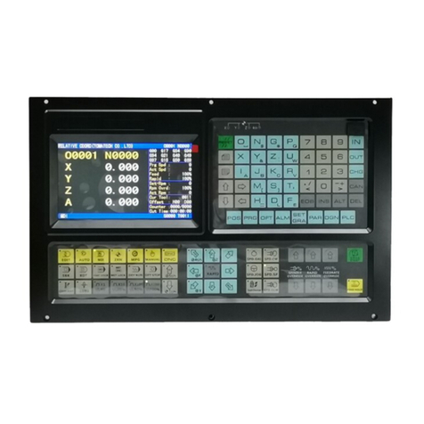
SEFRAM Sequencer COMPACT User manual

Sequencer COMPACT
Technical brochure
FI 72.0467.0118E
Page 1 / 42
PLACE GUTENBERG - 59175 TEMPLEMARS (France)
Tel: +33(0)3 20 60 49 49 - Fax: +33(0)3 20 95 59 62
Email: contact@sefram.eu Web: www.sefram.eu
Electronics dedicated to dedusting and air
quality

Sequencer COMPACT
Technical brochure
FI 72.0467.0118E
Page 2 / 42
DESCRIPTION
Sequencer COMPACT is an adjustable device for control
and full automatization of dedusting equipments, whose
declogging is done by pressured air injections.
Permanent control of differential pressure allows an optimal
efficiency according to the whole parameters for any type of
exploitation and product.
It is equipped of a MOTHER card and from 1 to 8
SEQUENCER cards
The system can manage up to 128 solenoïd valves (SV),
(8 SEQUENCER cards of 16 solenoïds valves) with a
control of electric fault on each SV card.
The system has :
- 4 TOR inputs: run order, compressed air presence, T2A
time (accelerated declogging ) and forced running.
- 1 analog input 4-20mA allowing reception of datas from
one system equipped with 4-20mA output,
- 4 RELAY output: general fault, high alarm dP, analog
input alarm and running order response.
- 1 COM. CDM allowing management of a dust sensor
CDM.
- 1 analog output 4-20mA for report of measure of pressure
loss value dP.
The device is adjustable according to the use of it, with
several protection levels by passwords.
All the running parameters can be seen and adjusted from
the front panel, through a color touch screen. Interface is
multilingual.
The Evolutions of declogging cycle and analog input,
running faults, dust and pressure measures are clearly
displayed.
A graphic representation of pressure, dust rejection and
analog input allows an easy control of their level.
An USB key can be plugged to the device and the user can
record all historical measures of sensors and all the faults.
The device also has counters of cycles done and
recordings of mini and maxi measured pressures.
SUMMARY
DESCRIPTION Page 2
CHARACTERISTICS Page 3
DIMENSIONS AND MOUNTING Page 4
PROTECTION Page 5
CONNECTIONS
MOTHER CARD Page 6
SEQUENCER DC CARD Page 8
SEQUENCER AC CARD Page 10
USER INTERFACE
Main page / Synoptic Page 12
In case of fault Page 13
Running fault page Page 14
Sequencer information page Page 15
Informations page pressure dP Page 16
Pressure dP graph Page 17
CDM informations dust sensor Page 18
Graph Dust Page 19
Dust measure
Graph
Analog input measure Page 20
Page Main Menu Page 21
Page Password setting Page 22
Page HMI Parameters Menu Page 23
Page Langage Menu Page 24
Page Manual Mode Menu Page 25
Page Info System Menu Page 26
Page
Faults History
Page 27
Page Parameters Page 28
Page Parameters Fan Page 29
Page Parameters Sequencer Page 30
Page Parameters CDM Page 32
Page Parameters Pressure Switch Page 33
Page Parameters Analog Input Page 34
Page Process/Modbus Link Page 35
FAULTS Page 36
RUNNING Page 38
RELAY OUTPUT Page 39
WARNING / CALIBRATION
Page 40
GENERAL INSTRUCTIONS OF Page 41
SAFETY,ASSEMBLY,
COMMISSIONNING AND
MAINTENANCE
WARRANTY Page 42
CONFORMITY Page 42

Sequencer COMPACT
Technical brochure
FI 72.0467.0118E
Page 3 / 42
CHARACTERISTICS
MOTHER CARD :
- Supply voltage
24Vdc (voltage to supply)
- Consumption < 250mA
- Characteristics of TOR inputs Voltage 24Vdc supplied by device
Charge current +/- 1 mA
- Characteristics of RELAY outputs Dry contact max : 125Vac/0.3A – 30Vdc/1A
(to be protected by user )
- Running temperature -20° to 55°C
- Storage temperature -20° to 65°C
SEQUENCER DC CARD :
Supply
Consumption
Solenoïd valves( SV ) voltage
SV consumption
24Vdc (voltage to supply)
<50 mA.
24Vdc (25W maxi)
1.6A max
SEQUENCER AC CARD :
Supply
Consumption
Solenoïd valves( SV ) voltage
SV consumption
24Vdc (voltage to supply)
<50 mA.
24Vac / 48Vac / 115Vac / 230Vac (voltage to supply )
According to power and voltage of the solenoid valve
TOUCH SCREEN :
- Size / Technology 4.3 inches / TFT LCD / Tactile Resistive
- Resolution / Colors 480x272 pixels / 65536 colors / Buzzer
- Date/time
- IP Battery 3V – CR2032
65
MEASURE OF DP :
- Scale 0-500 daPa
- Pressure max ( P+ > P- ) 400 mbar
- Precision classe 2 on a scale maxi detector (100 mbar)
→from 0 to 60°C this class takes into consideration linearity,
hysteresis, temperature and repetitiveness
- Response time to order dP 1 second
- Response time to alarm high/low
and threshold T2A
OUTPUT ANA 4-20mA :
5 seconds
- Description
- Type
- Calibration value of output 4-20mA
INPUT ANA 4-20mA :
- Description
- Type
Report of pressure loss measure
Integrated supply, not isolated
Charge maxi < 500 Ohms
4mA = 0 daPa
20mA = 500 daPa
Receiver signal 4-20mA
Passive
USB:
- type USB 1.0 or USB 2.0
- format FAT32

Sequencer COMPACT
Technical brochure
FI 72.0467.0118E
Page 4 / 42
DIMENSIONS
Dimensions MOTHER card: 157 x 123mm (L x l)
With snap-on mounting on support RAIL DIN.
Dimensions SEQUENCER DC card: 72 x 123mm (L x l)
With snap-on mounting on support RAIL DIN.
Dimensions SEQUENCER AC card: 90 x 123mm (L x l)
With snap-on mounting on support RAIL DIN.
Dimension of display: 129 x 103 x 39mm (L x l x P)
Window: 118.8 x 92.8mm (L x l)
CONNECTIONS PRESSURE
- Pressure pipe to be connected to the sensor : Polyurethane tube 4x2.5mm ( Tubing O.D x Tubing I.D)
Reference Example : SMC TU0425 .
Careful to respect the connections clean / dirty ! (See page 6)
- For use with pressure connections through partition, we recommend using the following references:
SMC M- 5ER
SMC M- 5AU -4
SMC 1511 8 / 6-1 / 8
Intended for use with the tube 6 / 8mm (connection to process)

Sequencer COMPACT
Technical brochure
FI 72.0467.0118E
Page 5 / 42
PROTECTION
The control voltage of the solenoïds valves (SV) are protected upstream to prevent any brake down of supplies in case
of a failed SV: short-circuit…
There is 1 common fuse for the 16 outputs. This fuse is on the corresponding output card.
Version DC Version AC
The fuse rating depends on order tension of the Solenoids Valves (SV) ( see board hereafter ) :
SV control voltage 24Vdc 24Vac 48Vac 115Vac 230Vac
Fuse rating 1.6A / F 1.6A / F 1A / F 1A / F 1A / F
Fuse Size 5x20mm Fuse Size 5x20mm

Sequencer COMPACT
Technical brochure
FI 72.0467.0118E
Page 6 / 42
Connections Mother card
ALARME Entrée
Analoqique
Supply 24Vdc
Link to IHM
L
in
k to sequencer card
Output Relay
running order
response
Output Relay
Alarm analog input:
-High Alarm
-Low Alarm
- or fault
Output Relay
General fault Output Relay
High alarm dP
Inputs TOR :
-Run order
-Compressed air
presence
-forced run
-
Forced running
Link to CDM
Analog Input
4-20mA Analog Output
4-20mA (dP)
Pressure switch
Dirty Air Clean Air

Sequencer COMPACT
Technical brochure
FI 72.0467.0118E
Page 7 / 42
Mother Card connection : example
Supply module not
included
Power supply
230VAC
50/60Hz
Inputs TOR :
-IN1: Run order
-IN2: Compressed air
presence
-IN3: forced run
-IN4: Forced running
Link to dust
control
sensor CDM
Link to
Sequencer
card
Link to sensor
with 4-20
output (as a
temperature
sensor)
dP
measure
output
GENERAL
DEFAULT
OUTPUT:
If default is
present:
contact
between C and
NC
HIGH dP
ALARM:
If dP measure
reaches the
high threshold,
contact
between C and
NC
ANALOG
INPUT
ALARM:
If 4-20 input
reaches the
threshold
alarm, contact
between C and
NC
RUNNING
ORDER
RESPONSE:
If running order
input is active,
contact between
C and NO
24VDC / GND

Sequencer COMPACT
Technical brochure
FI 72.0467.0118E
Page 8 / 42
Connections Sequencer DC card
Link to mother card :
RS485A output with SQ/A input
RS485B output with
SQ/B
input
Power supply
24Vdc
Order outputs SV 24Vdc (from 1 to 16)

Sequencer COMPACT
Technical brochure
FI 72.0467.0118E
Page 9 / 42
SEQUENCER CARD DC CONNECTION : Example
16x Solenoids valves outputs 24Vdc 25W
Card n°0
Link to
MOTHER
Card
Card n°0: SV1 to SV16

Sequencer COMPACT
Technical brochure
FI 72.0467.0118E
Page 10 / 42
Connections Sequencer DC card
Supply Voltage
24Vdc
Supply voltage SV
(AC)
PHASE
Order output SV from 1 to 16
Supply VAC (NEUTRAL)
Link to mother card :
RS485A output with SQ/A input
RS485B output with
SQ/B
input

Sequencer COMPACT
Technical brochure
FI 72.0467.0118E
Page 11 / 42
SEQUENCER CARD AC CONNECTION : Example
Card n°0
Card n°0: SV1 to SV16
16x Solenoids valves Vac outputs

Sequencer COMPACT
Technical brochure
FI 72.0467.0118E
Page 12 / 42
USER INTERFACE
Main Page / Synoptic
1: Informations about sequencer / state of the declogging cycle:
n° : Number of the last activated solenoïd valve ( SV )
T: x / y: x is the countdown time / y is the running time
If one touches this area: link towards informations display sequencer z
2: Display of load loss measure « dP » (daPa)
If one touches this area: link towards measure display « load loss dP ».
3: If press this area: link towards page « main menu ».
4: Display of the trend of dust emission during X minutes, % of the adjusted alarm threshold (see instruction CDM).
If one touches this area: link towards informations page of CDM / Measure of dust rate.
This display is ON only if a dust sensor has been validated into parameters.
Configuration of the dust sensor is available on Parameters Menu « Dust Sensor CDM »
5: Display of the value on analog input 4/20mA.
This value comes from the device which is connected to the analog input of the sequencer.
If one touches this area: link towards graph of analog input measure.
This display is ON only if an input has been validated into parameters.
Configuration of the 4-20mA signal is available on Parameters Menu « Analog Input »: name, unit…
6: Display of current protection level.
7: Indication about the state of the 4 inputs (see chapter about definition of inputs) :
•Running order
•T2A
•A/C presence
•Forced run
Green spot = the input is present / Gray spot = the input is absent
2
1
3
7
4
5
6

Sequencer COMPACT
Technical brochure
FI 72.0467.0118E
Page 13 / 42
In case of default:
1: Link towards
Page Current Defaults:
The button “Default present” is displayed on the screen as long as the default is present.
Some defaults automatically reset, but for some others, it is necessary to reset them manually (page current defaults).
Note:
- If the present display page is different than the main page, and if a new default appears, we move to main page
automatically.
- If the present display page is different than the main page, we move to main page automatically after 10 minutes
without activity on the screen (it does not happen if we are in manual mode).
1

Sequencer COMPACT
Technical brochure
FI 72.0467.0118E
Page 14 / 42
Page Current Defaults:
1: list of the present defaults with time
2: link towards general main page
3: link towards main page / synoptic
4: default reset
1
2 3 4

Sequencer COMPACT
Technical brochure
FI 72.0467.0118E
Page 15 / 42
Page Sequencer Informations
1:
displays the number of the last SV activated.
Remark : if there is not any declogging cycle since the device has been switched on, it indicates 0
2: countdown time of the running time
3: time in the cycle (step)
4: displays the number of the next SV which will be activated.
5: user counter or manufacturer counter of cycles done by the system
To reset user counter: press Reset area (enable at level 0, 1 and 2)
To reset manufacturer counter: press Reset area (enable at level 2)
6: Press the button to display the manufacturer counter or user counter
If « manufacturer » is displayed, the counter indicates the manufacturer counter
If « user » is displayed, the counter indicates the user counter
7: Value of the set point for maintenance intervention (number of declogging cycles, from 0 to 999 x 1000).
If number of cycles on manufacturer counter exceeds the set point, a fault message will appear: « Set point for
maintenance exceeded ».
It is necessary to reset the counter to cancel the default (enable at level 2)
8: setting level
9: link towards main page / synoptic
1
2
3
4
7
6
5

Sequencer COMPACT
Technical brochure
FI 72.0467.0118E
Page 16 / 42
Page Informations about the load loss dP
1: measure of the differential Pressure of the filter between the clean and dusty part (=dP) (daPa)
2: Max load loss measured dP (daPa)
To reset this value, press the button “RESET” (enable at level 2)
Remark:
- The max is set at value 0. This value will be updated when the first max value is observed.
- There is no max value during 3 seconds after the start of declogging cycle.
3: Mini load loss measured dP (daPa)
To reset this value, press the button “RESET” (enable at level 2)
Remark:
- The min is set at value 999. This value will be updated when the first min value is observed.
- There is no min value during 2 minutes after the start of the fan.
4: link toward the load loss dP graph
5: link towards main page / synoptic
1
2
3
45

Sequencer COMPACT
Technical brochure
FI 72.0467.0118E
Page 17 / 42
Page Graph of load loss dP
1: Curve of the load loss dP value, with time and date
Visualization of the x last running days of the device. The time x is depending to the sample rate, it is set from the
page Parameters of the pressure switch.
2: cursor to display value of the x last days
3: link towards information page load loss dP
4: link towards main page / synoptic
5: recording of values on USB key. (enable at setting level 2)
The system allows to get the 200 000 lasts values of load loss measures on the USB key.
The sample rate is adjustable between 1 to 60 sec (see on “pressure switch page parameters”).
Example: if the sample rate setting is 1 record/60sec, then the total recording time is equal to 138 days.
To insert the USB key, it is necessary to open the box and insert an USB key at the back of the HMI.
Once USB key is inserted, wait the audio signal, which indicates that the system has identified the USB key.
Press USB recording key, validate and wait for the message “recording with success” / “recording fault”.
Before to unplug the USB key, must go to the Page Menu Parameters HMI and press the button “Unplug USB key”.
The recorded folder is a *.csv type. Compatible with software of board conception, as Excel.
The name of folder is like : dP_ date _ NumSerie xxxxxxxxxxxxxxxx.csv
This step can take a few minutes.
1
2
4
5
3

Sequencer COMPACT
Technical brochure
FI 72.0467.0118E
Page 18 / 42
Page Informations CDM / Measure of rejected dust rate
We suggest to consult the user’s manual of the dust sensor to have a good knowing of this sensor:
“CDM–Sensor to monitor dust emission FI 72.0401.0115E”
1: Instantaneous of dust emission rate. Value in % regarding the alarm threshold.
Alarm threshold = n2 x PR value
2: Mean value calculated on X minutes of the dust reject.
Value in % regarding the alarm threshold.
3: link towards main page / synoptic
4: link towards graphs of dust emission measures
1
2
3 4

Sequencer COMPACT
Technical brochure
FI 72.0467.0118E
Page 19 / 42
Page Graph Measures of the dust emission
1: curve of dust emission measures timestamped (1 sample/min).
Visualization of the x last running days of the device. The time x is depending to the sample rate, it is set from the
page Parameters of the Dust Sensor CDM.
2: cursor to display value of the x last days
3: link towards page informations CDM / Measure of dust emission rate
4: link towards main page / synoptic
5: recording of values on USB key. (enable at setting level 2)
The system allows to get the 600 000 lasts measures of dust emission on the USB key.
The sample rate is adjustable between 1 to 60 sec (see on “Dust Sensor CDM page parameters”).
Example: if the sample rate setting is 1 record/60sec, then the total recording time is equal to 416 days.
To insert the USB key, it is necessary to open the box and insert an USB key at the back of the HMI.
Once USB key is inserted, wait the audio signal, which indicates that the system has identified the USB key.
Press USB recording key, validate and wait for the message “recording with success” / “recording fault”.
Before to unplug the USB key, must go to the Page Menu Parameters HMI and press the button “Unplug USB key”.
The recorded folder is a *.csv type. Compatible with software of board conception, as Excel.
The name of folder is like : DustSensor_ date _ NumSerie xxxxxxxxxxxxxxxx.csv
1
2
4
5
3

Sequencer COMPACT
Technical brochure
FI 72.0467.0118E
Page 20 / 42
Page Graph Measures of the Analog Input
1: curves of values on Analog Input 4-20mA signal:
- curve measure
- Alarm High Threshold, adjusted in the page Menu Parameters «Analog Input»
- Alarm Low Threshold, adjusted in the page Menu Parameters «Analog Input»
Visualization of the x last running days of the device. The time x is depending to the sample rate, it is set from the
page Parameters of the Analog Input.
2: cursor to display values of the last days
3: recording of values on USB key (enable at setting level 2)
The system allows to get the 200 000 lasts values of load loss measures on the USB key.
The sample rate is adjustable between 1 to 60 sec (see on “Pressure Switch page parameters”).
Example: if the sample rate setting is 1 record/60sec, then the total recording time is equal to 138 days.
To insert the USB key, it is necessary to open the box and insert an USB key at the back of the HMI.
Once USB key is inserted, wait the audio signal, which indicates that the system has identified the USB key.
Press USB recording key, validate and wait for the message “recording with success” / “recording fault”.
Before to unplug the USB key, must go to the Page Menu Parameters HMI and press the button “Unplug USB key”.
The recorded folder is a *.csv type. Compatible with software of board conception, as Excel
The name of folder is like: InAna_ date _ NumSerie xxxxxxxxxxxxxxxx.csv
4: link towards main page / synoptic
4
3
1
2
Table of contents
Popular Control System manuals by other brands
Evonicfires
Evonicfires E-Touch Installation & user's instructions

AER
AER 5R5-384 user manual
Spraying Systems
Spraying Systems TeeJet Technologies 744E user manual
Pro-tec
Pro-tec Algo-Tec 6400 Quick operating guide
Geobrugg
Geobrugg RXE-1000 product manual
Cooper Wiring Devices
Cooper Wiring Devices Aspire RF user guide
NCE
NCE POWER PRO DCC quick start guide

Comunello
Comunello BORDER 400 Installation and user manual
Emerson
Emerson White Rodgers 50A65-5165 installation instructions
ALCON
ALCON Manor-2101 quick start guide
Leb Electronics
Leb Electronics SHUT Instructions for installation, use and maintenance
Thermo King
Thermo King TS-200 manual
