NCE POWER PRO DCC User manual
Wireless Supplement
for
Cab04p, Cab04e, Cab05
Versions 1.0 through 1.3
Operate your cab without “plugging in”
Features:
‚True two way wireless capability for your Cab04/Cab05
‚All features of your Cab are available without plugging in
‚Uses ANY battery chemistry: Alkaline, NiCad, NiMH, Lithium, Lead Acid
‚40+ hours of operation (typical) with Alkaline batteries
‚Automatic switchover to bus power when plugged in
‚Graceful degradation of operation when approaching maximum range
No guarantees are made by NCE or authorized NCE dealers as to the suitability of this product for its intended
use.
As with all radio products, communication integrity in the presence of interference can not be guaranteed.
This book, schematics, drawings and artwork copyright 2002
NCE Corporation Webster, NY 14580
POWER PRO DCC
Digital Command Control
TM

About your wireless Cab04/05:
The wireless option for the Cab04/05 is designed to eliminate the need for tethered operation of an
NCE Cab. All present and planned features of the cab are usable while untethered from the cab
bus. The adapter is battery powered and will supply power for both cab operation and the adapter
itself. Although the installed wireless adapter is designed to operate at any voltage from 2 to 16
volts we recommend the use of 2 AAA cells. The Cab has a built in battery chamber for 2 AAA
battery cells. The transmitter power of the cab is .00035 Watts. By comparison your cell phone
can put out 3 Watts or about 10,000 times the power of the Cab. For this reason a general
discussion of wireless communications follows.
Wireless communications:
We are continuously asked about the operating distance of the wireless cab. There are many
factors governing the useful range of wireless products. The Cab04/5-R operates in the ISM
(Industrial, Scientific and Medical) radio band at 916.5 MegaHertz (Mhz). Many cordless phones,
wireless computer networks, home automation systems, and wireless security devices also operate
in this portion of the radio band and all contribute to radio interference. In any radio system,
propagation of the radio signal will suffer in the presence of ‘in band’ intererence. When devices
operate in the same frequency band they may contribute interference to the point where your cab
may not work at all. On the other hand your wireless cab may interfere with the operation of the
other devices you already own. Radio waves are like one big telephone ‘party line’ where everyone
is talking at once. A device using these radio waves must attempt to sort out what ‘voices’ are
relevant to its operation and which ones are ‘noise’. If there is too much noise it can’t do this
successfully and will operate poorly or not at all.
Indoor radio propagation is an issue for special consideration. The human body readily absorbs RF
energy in the frequency band used by the cab radio. Placement of the base station can mitigate
blocking of the radio signal due to human body absorption. In most indoor situations ‘dead spots’
can be found where reception is very difficult. These can occur even if there appears to be a direct
line of sight between the transmitter and receiver. These dead spots, or ‘nulls’, are the result of
multiple radio transmission paths between two points caused by reflections off metal objects such
as steel beams, screen wire, concrete rebar, metal door and window frames, ceiling tile frames,
model railroad track, etc. Nulls occur where the path lengths differ by an odd ½ wavelength (about
6 inches at 900 MHz). Deep nulls are usually very localized and can be avoided by moving slightly,
usually only a few inches. When performing complex tasks involving many messages displayed on
the Cab, communications between the cab and command station may take longer than expected
thus slowing down your programming. In these instances you may find it more expedient to plug in
the cab while doing extensive programming or system setup.
Operation of the Cab:
To turn on the cab:
Press “HORN”. The cab will activate and the LED very briefly flash. After the cab communicates
with the base station normal operations can begin just as if you were plugged in to the cab bus.
Description of LED activity:
The LED on top of the cab will flicker every time it communicates with the base station. A regular
‘pulse’ of this LED indicates good quality communications. The flickering will become erratic when
you are getting out of range from the base station. You can use this LED activity to ‘map out’ weak
signal areas and ‘nulls’ of the layout room.
Priority is placed on commands getting from the cab to the base station. As you approach the
maximum range of the cab, updates to the LED (on/off) will lag behind the commands being sent to
the base. If the base station is not able to LED updates it will try to re-send them 16 times before
giving up. The base station LEDs flash brightly when it is trying to send display update information.
To turn off the cab:
Just let it “timeout” and shut itself off. Optionally, you can also program the “OPTION” button to be
the “EXPN” button (see your CAB04/5 manual). Then press “OPTION” followed by “1” to turn the
cab off. .
Automatic shutdown:
As it comes from the factory, the cab will automatically shut itself off after 5 munites of inactivity.
**Last revised: 19 September 2004 Page 2 Cab04/05 wireless supplement
Cab Addresses:
Wireless Cab04p, Cab04e and Cab05 must be set to cab addresses in the range of 19-49
Wireless ProCabs must be set to cab addresses in the range of 2-17.
Cabs with addresses outside these ranges will not work wireless.
Layout ID:
The layout ID is used in situations where multiple layouts using the NCE wireless are running in the
same area. When the ID is set to 0 all layout IDs are ignored by the cab and it will communicate
with any base station it hears. When set to 1,2 or 3 the layout ID must match between the cab and
base station. The layout ID is set by pressing “EXPN” and selecting option #2 (SETUP RADIO).
Press “ENTER” to skip setting/changing the automatic shutdown timer. Press 0 to 3 to set the
Layout ID. Only values of 0 to 3 are accepted. Press enter and the cab should return to normal
operation. The Layout ID is not supported in current versions of the RB01 base station.
Tips:
When you press a button on the cab press and hold for about a second. You don’t have to press
harder than normal but pressing slightly longer results in better performance.
We recommend having several our UTP or DIN plug-in panels located around the layout where you
can plug in the cab in case the battery goes dead or conditions such as severe interference cause
loss of control via radio. We usually hang a short cab cable about 2 feet long from a small number
these panels to facilitate plugging in in an emergency.
The LED on the cab flashes every time it sends a cab status update to the base station.
You can use this flashing to map out the dead spots in the layout room. The cab is communicating
best when the LED has a steady flicker. Move about the room noting where the spots wher the
flashing stops or becomes erratic. Then move the base station to a different location until you get
good reception at at the most important operating spots.
The cab may not operate when you get within 1 foot (300mm) of the base station (other cabs will
still operate normally). The LED on the cab will flicker but the will not seem to communicate with
the base station. This is due to ’overloading’ of the base station receiver. Due to the extreme low
power of the cab radios we’ve had to make the radio receivers in the base station very sensitive.
This can result in the receiver being overloaded when a cab is too close.
The Cab with wireless seems to propogate the radio signal better to the sides of the cab than to the
front or rear. Turning the cab sideways to the base station will sometimes result in better
communications.
The cab works much better with the antenna vertical rather than pointing the antenna at the base
station.
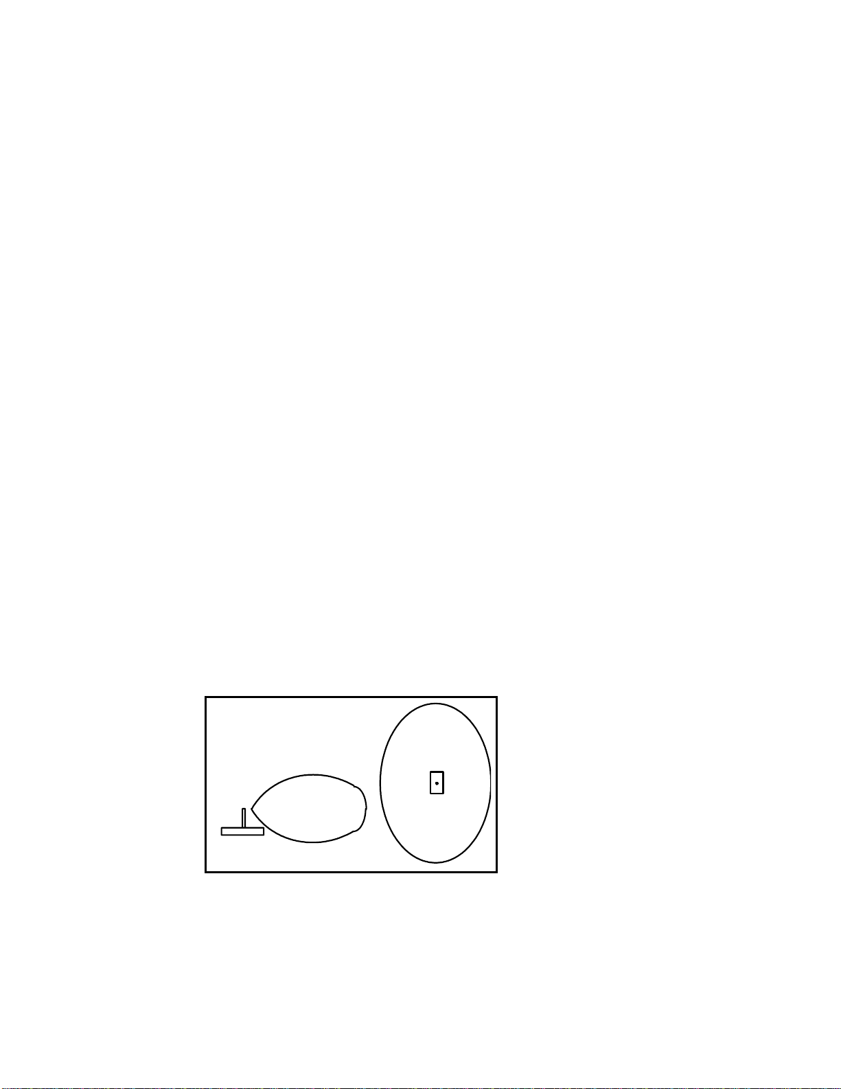
In crowded layout rooms we’ve had good luck attaching the base station to the ceiling with the
antenna pointing down. See the diagram below for how the radio signal propagates from the
antenna.
**Last revised: 19 September 2004 Page 3 Cab04/05 wireless supplement
Side View
Antenna Radiation Patterns
from RB01 Base Station

This device complies with Part 15 of the FCC rules. Operation is subject to the following conditions (1) this
device may not cause harmful interference and (2) this device must accept any interference received, including
interference that may cause undesired operation.
Warranty
This product is fully factory tested and warranted against manufacturing defects for a period of 1 year. As the
circumstances under which this product is installed can not be controlled, failure of the product due to installation
problems can not be warranted. This includes misuse, miswiring, operation under conditions beyond the design
range of the product. No guarantees are expressed or implied as to the suitability of the product for its intended use
by the purchaser. No guarantees can be made as to the communications range or performance of this product in
the presence of radio or other electromagnetic interference. It is possible that interference can cause undesired
operation including loss of control of speed, direction etc. Damage to purchaser’s equipment due to loss of control
is not warranted or covered by NCE.
For warranty or non-warranty replacement send the decoder (and any payment, if required) to:
NCE Warranty Center
899 Ridge Road
Webster, New York 14580
Spare Parts:
Spare parts for your cab or RU01 wireless adapter may be ordered from the list below. $4 US
will be added to your order for US priority mail and packaging. Check or credit card will be
accepted.
Send parts orders to:
NCE Spare Parts
899 Ridge Road
Webster, New York 14580
**Last revised: 19 September 2004 Page 4 Cab04/05 wireless supplement
$8.00Rubber keypad for Cab04/05
$1.50Cab04/05 battery holder
$1.00Cab04/05 screws (set of 4)
$7.00Cab04/05 rear cover w/battery door
$2.00ProCab screws (set of 9)
$8.00Antenna
$3.00ProCab battery clip set w/wires
$8.00Rubber keypad for ProCab
$10.00Procab top
$10.00ProCab bottom w/ battery door
Price (US $)Description
Table of contents
Other NCE Control System manuals


