SEFRAM SFX+V2 User manual

SEQUENCER WITH
DIFFERENTIAL PRESSURE
SWITCH
Technical notice
FI 72.0567.0221E
Page 2 / 45
SUMMARY :
DESCRIPTION :
The SFX+V2 is an adjustable device for the control and
automatization of declogging equipment, whose declogging is done
by compressed air injections.
It can manage filters organized in several cells (= compartments)
and with several compressed air reservoirs.
Depending on the configuration, declogging is carried out in
ONLINE or OFFLINE mode.
The SFX+V2 manages various controls, such as electric
consumption of SV, position of cell insulation, compressed air
consumption on tanks, dust emissions ...
The SFX+V2 has a historical record of faults and events.
The SFX+V2 incorporates the functional program corresponding
to the configuration of the filter. Adjustment of some parameters can
be done easily on site thanks to the user interface.
The user interface is a multi-lingual 7 "colors touchscreen. Access
is protected at several levels by passwords.
The SFX+V2 has a native RS485 Modbus communication in
order to communicate with the outside (ex: supervision).
It can be adapted to multiple fieldbuses thanks to a gateway also
integrated in the SFX+V2 cabinet.
The SFX+V2, depending of the filter configuration, is composed
of a master box/cabinet and several slave boxes. A configuration in
form of a bus allows, especially, to reduce the wiring compared to a
conventional configuration. In fact, the slave boxes can be placed
near the declogging solenoid valves while collecting the information
necessary for proper declogging (compressed air pressures, cell
position) and by controlling the cell and tank isolation.
For each SFX+V2, an electrical diagram is associated. Refer to it
for connections and dimensions.
Depending on the filter configuration, some parts of this manual
are not used.
Page
- DESCRIPTION
2
- CHARACTERISTICS
Master box/cabinet
Slaves boxes
4
4
5
- CENTRAL UNIT BOARD
6
- SLAVE BOARD
Coding
Protections
7
7
8
- USER INTERFACE
General
Cycle
About
security
HMI
Languages
Parameters
Sequencer / filter configuration
Online shooting sequence
Operating time
Counters
Dust emission
Compressed air
Customer communication
Manual mode
Historical
Faults
Events
Current faults
10
10
11
12
13
14
15
16
17
22
24
26
27
28
29
30
31
32
34
36
OPERATION
Putting in service
Online
Offline
37
37
38
39
- FAULT CHECK
Electrical faults
Mini pressure faults
re-inflation tank faults
SV non-opening faults
Dust emission faults
Link faults
Cell opening / closing faults
Other faults
40
40
40
41
41
42
43
43
43
- PRECAUTIONS
44
- WARRANTY
44
- CERTIFICATE
44
- GENERAL INSTRUCTIONS OF
SAFETY, ASSEMBLY,
COMMISSIONNING AND
MAINTENANCE
45
- ANNEX
SEQUENCER WITH
DIFFERENTIAL PRESSURE
SWITCH
Technical notice
FI 72.0567.0221E
Page 3 / 45
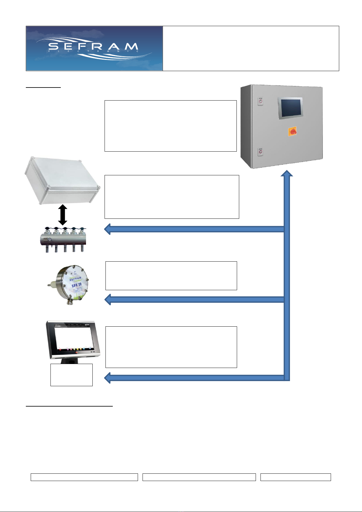
Overview:
Maximum configuration :
Number of cells: 32
Number of SV per cell: 64 - with a maximum total of 512 SV on the complete filter.
Number of slave boxes: 32
Number of tanks: 32
Number of dust emission probe: 16
Number of digital inputs: 12 (extension possibility)
Number of relay outputs: 6 (extension possibility)
MASTER box/cabinet:
- 7 "touch color HMI
- digital inputs management
- RELAY output management
- analog input / output 4 / 20mA
- integrated dP pressure switch
CUSTOMER communication:
MODBUS RTU protocol - native RS485
On demand :
PROFIBUS, MODBUS TCP / IP,
PROFINET, others ...
PLC /DCS
superviseur
SLAVE boxes: (up to 32)
- Management of up to 18 EV outputs per box
- Integrated Air/Compressed pressure switch
- Cell / tank isolation management
- Cell position control
Dust emission check
- Management of up to 16 dust emission
probes

SEQUENCER WITH
DIFFERENTIAL PRESSURE
SWITCH
Technical notice
FI 72.0567.0221E
Page 4 / 45
CHARACTERISTICS:
Master box/cabinet :
- Supply voltage
230VAC 50/60Hz
Other : on request
- Consumption
According to configuration
- General protection
By circuit breaker
- Characteristics of digital inputs:
Voltage: 24VDC supplied by the device
Charge current +/- 1mA
- Relay contact characteristics:
dry contact. max: 125VAC / 0.3A - 30VDC / 1A
(to be protected by the user)
- Operating temperature:
-20°C to 55°C
- Storage temperature:
-20° to 70° C
- Box / cabinet
RAL7035 painted steel dimensions depending on configuration
PC RAL7035 on request - IP55
DP pressure load loss measure (on request):
- Scale
0-500daPa
- maxi pressure ( P+ > P- )
400 mbar
- precision
class 2 on the maximum sensor scale (100 mbar)
→ from 0 to 60 ° C this class takes into account linearity,
hysteresis, the effects of temperature and repeatability
- DP order response time
1 second
- High / low alarm response time
5 seconds
4-20mA analog output (on request):
- Description
Transfer of the pressure load loss measure (DP)
- Type
Integrated power supply, non-isolated
Maximum load <500 Ohms
- Calibration value
4 mA = 0 daPa / 20mA = 500 daPa
4-20mA analog input (on request):
- Description
4-20mA signal receiver
- Type
Passive
- Calibration value
Configuration at the HMI
Touch screen :
- Size / Technology
7 inch / TFT LCD / Resistive touchscreen / buzzer
- Resolution / Colors
800 x 480 / 65536 colors
- USB
USB Slave Vers 2.0
- Date / time calendar
Battery lithium 3V Type CR2032
- protection index
IP65 / NEMA 4
Communication with outside (ex: to supervision):
- protocol
MODBUS - RTU / RS485 (2 wires) - not isolated
Note: Gateway available for other type of network.
- ID number
From 1 to 147
- speed
2400, 4800, 9600, 19200, 38400, 57600 or 115200 bauds
- Type
8N1, 8N2, 8E1 or 8O1
- Max distance
Up to 1200m
- Cable to use
Shielded twisted pair cable; STP type

SEQUENCER WITH
DIFFERENTIAL PRESSURE
SWITCH
Technical notice
FI 72.0567.0221E
Page 5 / 45
Slaves boxes :
- Supply voltage :
Several versions
Solenoid valves voltage DC
Version supply AC : 100 to 240V 50-60 Hz
Version supply DC : 24Vdc
Solenoid valves voltage AC
115V/230V 10% 50-60 Hz
24V/48V 10% 50-60 Hz
- Consumption max :
Solenoid valves voltage DC
Version supply AC : 1A
Version supply: 2.5A
Solenoid valves voltage AC
5VA + SV consumption
- Number of solenoid valve outputs
18 max
- Electrical connection / cable outlet
3 versions: Individual- multi - Integrated pilots
- Protections :
Solenoid valves voltage AC : see table 1 page 8
Solenoid valves voltage DC : see table 2 page 9
- Solenoid valve voltage:
According to version:
24VDC integrated / Pmax 25W or 40W
24V / 48V / 115V / 230VAC 50-60Hz / Pmax 25VA or 45A
Others on request
- Characteristics of digital inputs:
Voltage: 24VDC supplied by the device
Charge current +/- 1mA
- Relay contact characteristics:
dry contact. max: 125VAC / 0.3A - 30VDC / 1A
(to be protected by the user)
- Operating temperature:
-20° to 60°C
Integrated pilot version: 0°C to 60°C
- Storage temperature:
-20° to 70° C
- Case :
Material ABS - IP65
Material PC - IP65 on request
Compressed air pressure measure:
- Scale
0 –6 Bars
Display accuracy: 0.1Bar
- max pressure
17 Bars
- Precision
1.5% on the maximum sensor scale (10Bars)
→ from 0 to 50 ° C this precision takes into account linearity,
hysteresis, the effects of temperature and repetitiveness
- Humidity
0 to 95% RH –not condensed
- Output 4-20mA
On request
Integrated power supply, non-isolated - Max load <500 ohms
Note : Read the electrical diagram supplied with the sequencer in order to be aware its configuration and specific
characteristics.
SEQUENCER WITH
DIFFERENTIAL PRESSURE
SWITCH
Technical notice
FI 72.0567.0221E
Page 6 / 45
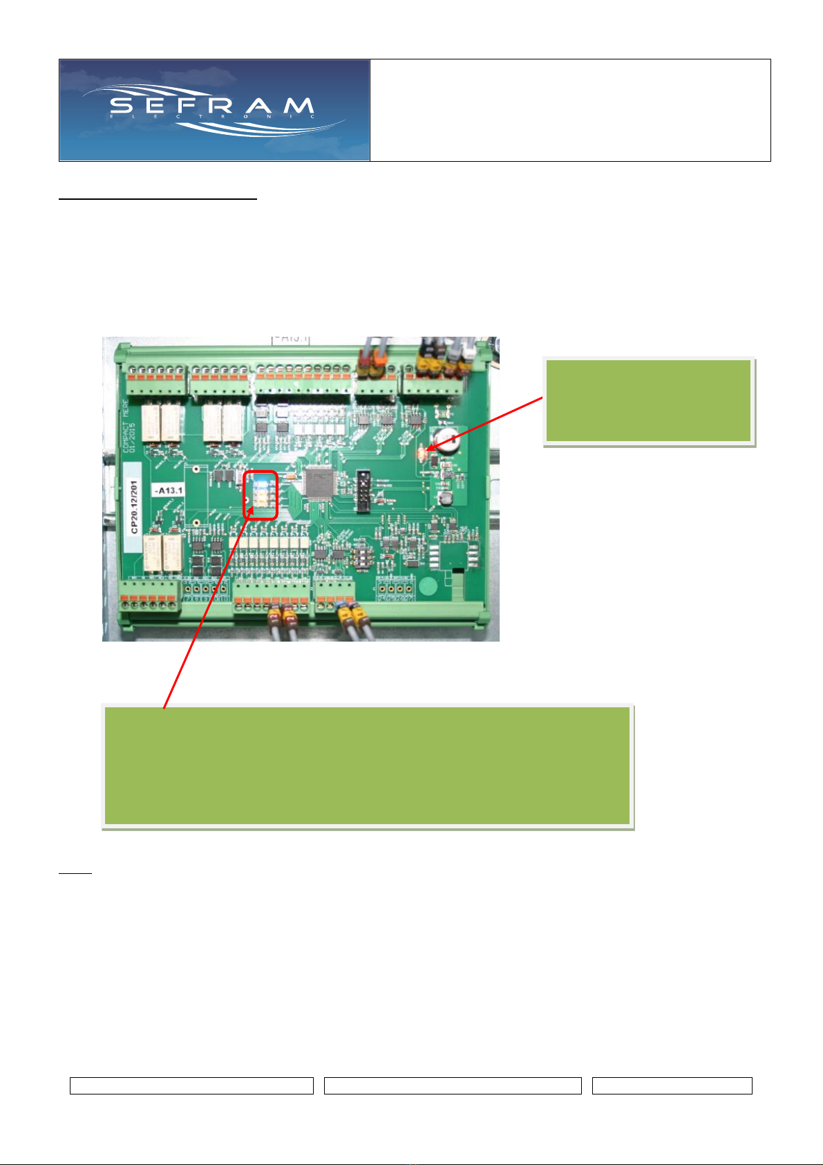
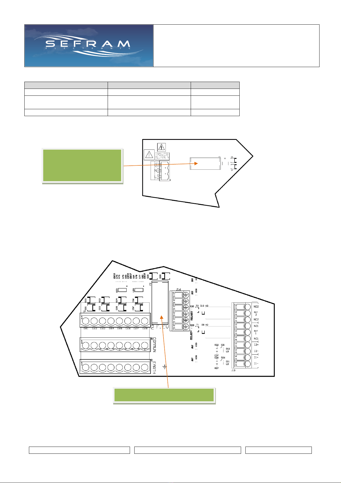
CENTRAL UNIT BOARD :
This board is located in the master box/cabinet. It is the heart of the SFX+V2 system.
It contains all the filter configuration as well as its settings.
It constantly communicates with the slave boxes and the HMI screen.
It processes the exchanges coming from the Modbus RTU client communication.
Depending on the configuration, it can be equipped with a pressure sensor for measuring the load loss pressure,
4-20mA analog input and output, several digital inputs and relay outputs.
Note: a kit exists to backup or restore the SFX+V2 settings to or from a disk file. This kit, consisting of a USB cord
and PC software, connects to this card. See the associated documentation (FI72.05666)
Red led:
Permanently on, signal of the
presence of the 24VDC
power supply
Blue LED: flashes regularly (1s) if the central unit is working
Yellow LED: representative of exchanges with the HMI screen
Green LED: representative of exchanges with Modbus client communication (or
exchange with gateway in the case of Profibus communication,
TCP / IP, Profinet ...)
Red LED: representative of exchanges with the slave boxes
SEQUENCER WITH
DIFFERENTIAL PRESSURE
SWITCH
Technical notice
FI 72.0567.0221E
Page 7 / 45
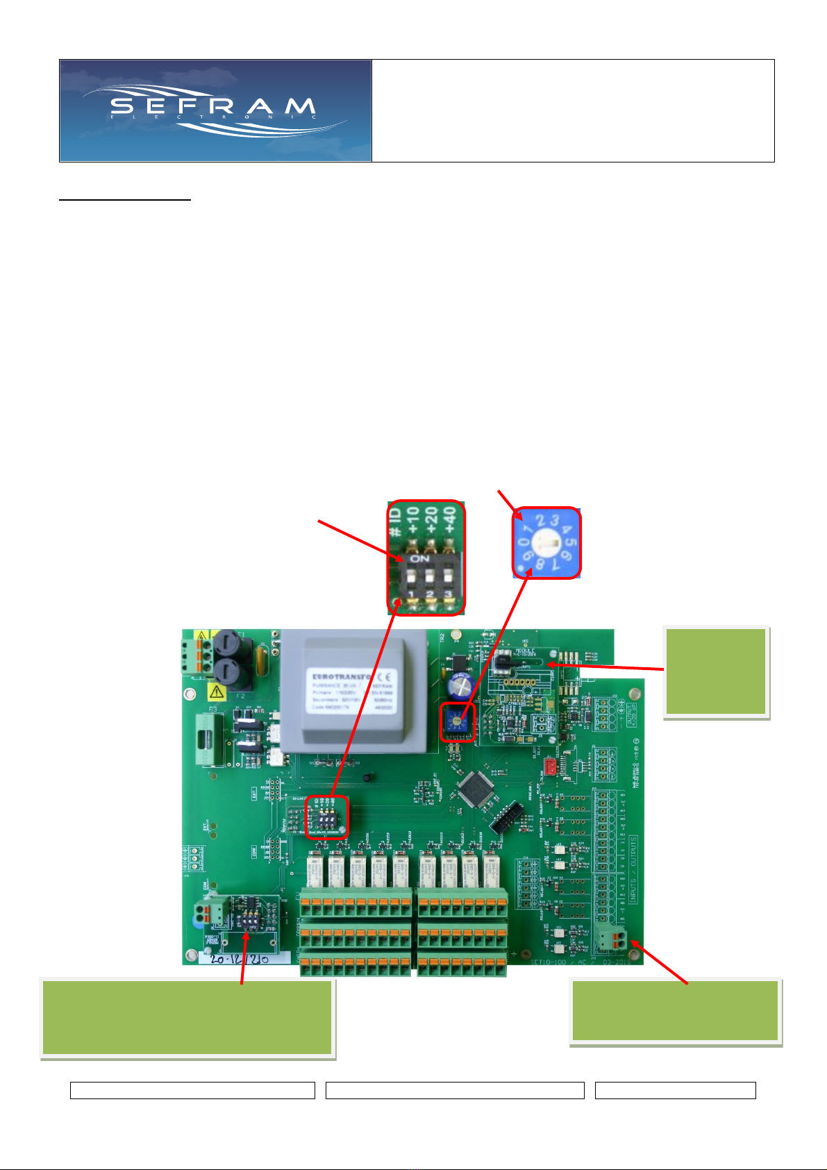
SLAVE BOARD :
This board is located in the slave box.
Depending on the configuration, it can be equipped with a pressure sensor for measuring the compressed air in a
tank with the possibility of a 4-20mA output for measure transfer.
It can be equipped with digital inputs and outputs to control the isolation of a tank or the isolation of a cell with
position control.
It manages the activation of a maximum of 18 SV while controlling the electrical and compressed air consumption.
A digital input (for dry contact) is provided on this board in order to make locally, on the concerned slave, a
sequential activation of its SV outputs: at each pulse, a shot is made followed by a pause time. If the input remains
closed (= 1), then the shots follow. Be carreful: these forced locally activation are made independently of the
controls and automation which are managed by the master box/cabinet.
Several slave boxes are used in an SFX+V2.
Each box is identified on the bus by a unique number.
This identifier determines the role of the box in the configuration of the filter (→see associated electrical diagram of
the SFX+V2). To set this number, the card has a rotary switch and microswitches in order to perform the coding:
the number is formed by the position of the rotary switch (0 à 9)
and by adding 10 if SW1 put ON
20 if SW2 put ON
40 if SW3 put ON
Note: the number can therefore
vary from 1 to 79.
Digital input: forcing activation
of SV output.
Be carreful: see above
Board
compressed
air
sensor
Slave box bus communication board
if the last box on the bus, put the central
switch to "ON"

SEQUENCER WITH
DIFFERENTIAL PRESSURE
SWITCH
Technical notice
FI 72.0567.0221E
Page 8 / 45
There are two leds (yellow and red) on the slave board:
Note: possibility of having a local user interface: contact us.
Protections on slave board :
Table 1 : Voltage solenoid valves AC
Supply voltage
230VAC
115VAC
48VAC
24VAC
Solenoids valves voltage
230VAC
48VAC
48VAC
24VAC
24VAC
24VAC
115VAC
48VAC
24VAC
fuse F1 caliber
General protection
F1A
F1A
F1.6A
F1.6A
fuse F2 caliber
General protection
F1A
F1A
F1.6A
F1.6A
fuse F3 caliber
SV protection
F1A
F1A
F1A
F1A
The protection fuses are accessible after dismounting the front panel of the box. The fuses are located at the top left
of the board:
Fuses F1 and F2 :
Device general protection
5x20mm
Caliber: see table 1
Fuse F3 :
SV outputs protection
5x20mm
Caliber: see table 1
If communication on slave bus detected:
Yellow led: representative of receptions (RX)
Red led: representative of transmissions (TX)
If no communication detected on slave bus:
Yellow led: off
Red led: flashes regularly
SEQUENCER WITH
DIFFERENTIAL PRESSURE
SWITCH
Technical notice
FI 72.0567.0221E
Page 9 / 45
Table 2 : Voltage solenoid valves DC
Supply voltage
100 –240VAC
24VDC
Solenoids valves voltage
24VDC
24VDC
General protection
Self-protected power supply
against overcurrents
F2.5A
SV protection
F1.6A
F1.6A
In the 24V DC power supply version only, the general protection fuse is accessible after removing the front panel of
the box. The fuse is located at the top left of the board:
The SV output protection fuse is accessible after removing the front panel of the cabinet. It is located at the bottom
right of the map:
Fuse: SV output protection
Fuse:
General protection
24VDC power supply
version only

SEQUENCER WITH
DIFFERENTIAL PRESSURE
SWITCH
Technical notice
FI 72.0567.0221E
Page 10 / 45
USER INTERFACE :
General :
1. Name of the page
2. Current date and time
3. Current security level
The possible actions by the HMI are associated with the security level in which the system is
See page Security for more information
: link to CYCLE page
: link to previous page
: link to next page
3
2
1
SEQUENCER WITH
DIFFERENTIAL PRESSURE
SWITCH
Technical notice
FI 72.0567.0221E
Page 11 / 45
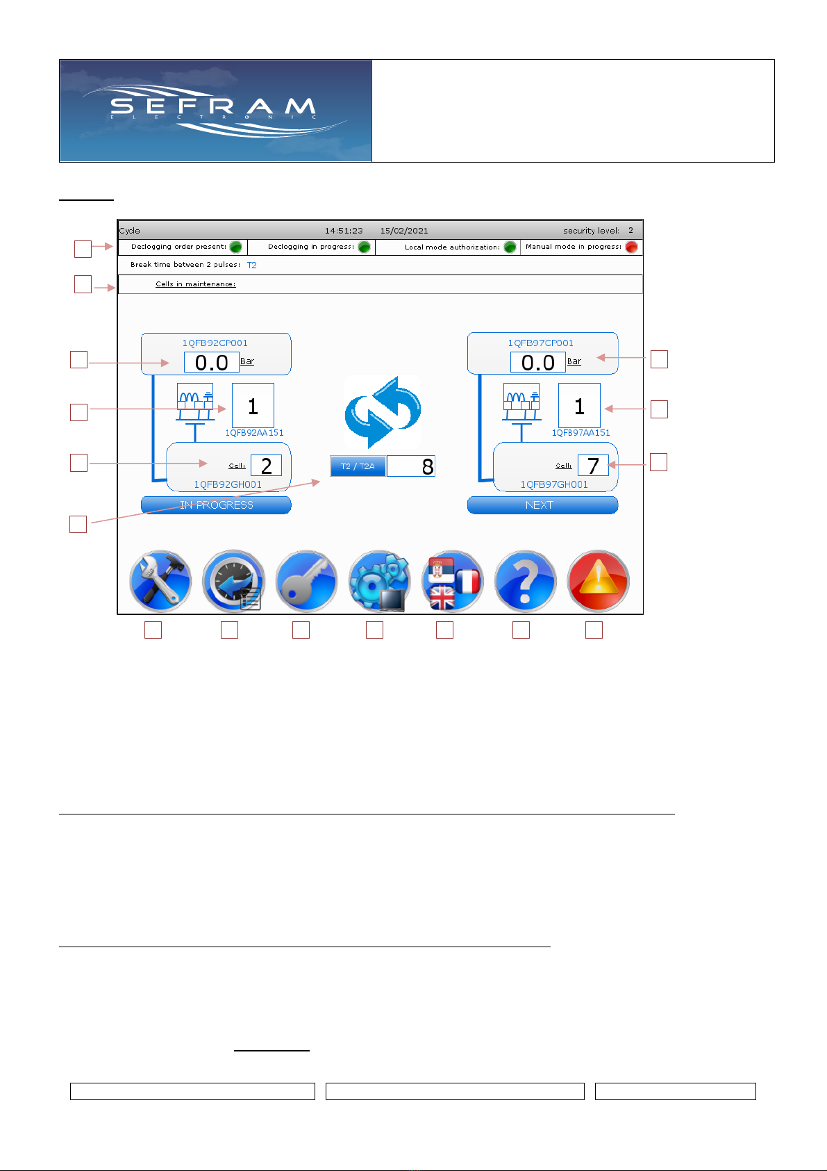
Cycle :
1. Visual on the run orders present / operation in progress
Information transmitted by the DCS via a COM or by manual override via the HMI
These operating orders come from the COM DCS according to the MODBUS exchange table specific to
the configuration
RED : inactive
GREEN = active
2. Display of the number of cells in maintenance. A cell in maintenance cannot be declogged.
All the declogging solenoid valves associated with a cell in maintenance will not be activated (no pulse).
Points 3, 4 and 5 indicate information on the solenoid valve being activated or the last one activated.
Note: nothing is visible if declogging has not yet started (in the case of power on)
3. Measure of the pressure (compressed air) of the associated tank. Display of the name given to the tank.
4. Number of the solenoid valve of the associated cell. Display of the name given to the solenoid valve.
5. Number of the associated cell. Display of the name given to the cell.
6. Current declogging cycle time / Time countdown
Points 7, 8 and 9 indicate information on the next solenoid valve to be activated.
Note: nothing is visible if no steps in the sequence are available.
7. Measure of the pressure (compressed air) of the associated tank. Display of the name given to the tank.
8. Number of the solenoid valve of the associated cell. Display of the name given to the solenoid valve.
9. Number of the associated cell. Display of the name given to the cell.
10. Link to the pages of Parameters
1
2
3
4
5
7
8
9
10
11
12
13
14
15
16
6
SEQUENCER WITH
DIFFERENTIAL PRESSURE
SWITCH
Technical notice
FI 72.0567.0221E
Page 12 / 45
11. Link to the pages of Historical : faults and events
12. Link to the page Security
13. Link to the page HMI parameters
14. Link to the page Langue
15. Link to the page A propos de
16. Link to the page Current faults. Appears only if at least 1 current fault is present
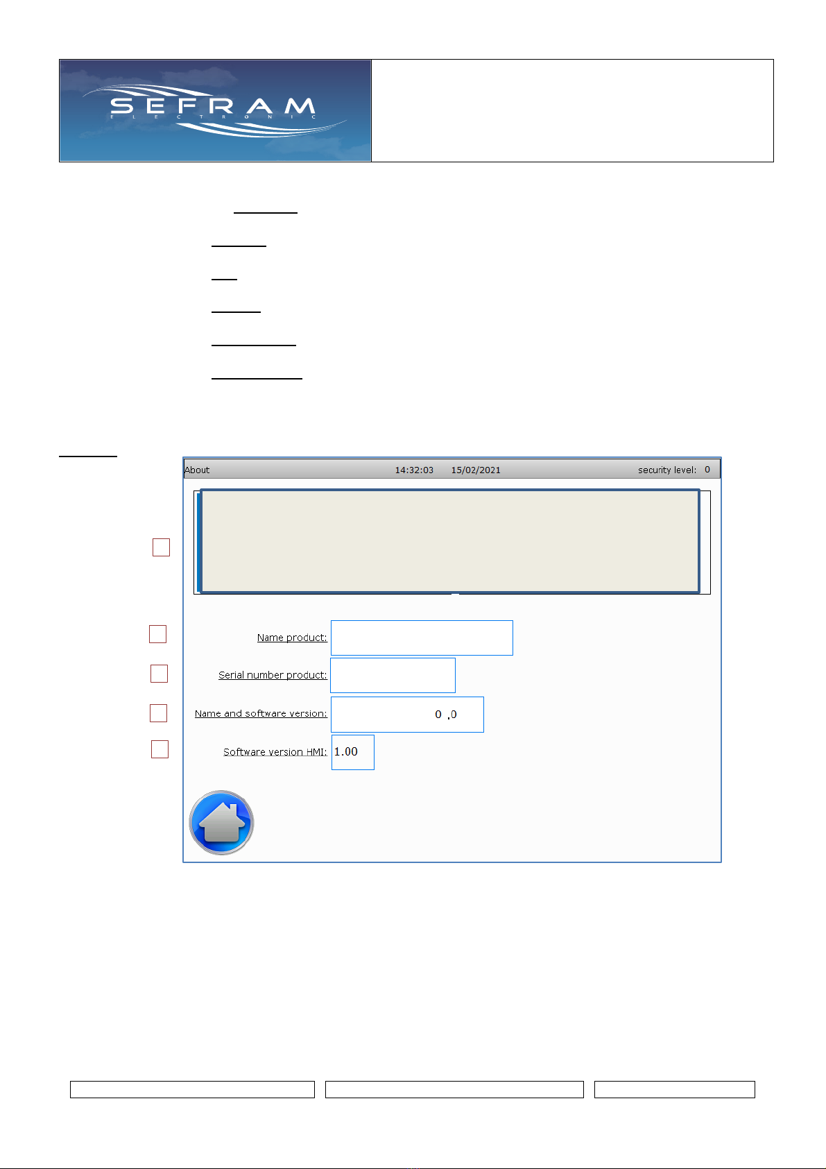
About :
1. Contact details of the manufacturer
2. Product name.
configurable at Manufacturer level
3. Product serial number
4. Name and software version of the central unit board integrated in the master cabinet
5. Software version of the HMI
1
2
3
4
5

SEQUENCER WITH
DIFFERENTIAL PRESSURE
SWITCH
Technical notice
FI 72.0567.0221E
Page 13 / 45
Security :
The possible actions by the HMI are associated with the security level in which the system is.
Each level of security is password protected.
security
Default
password
Navigation
Visualization
Reset faults
Historical
clear
Modifications
and saving of
operating
parameters
Changes to the
sequencer
configuration
Import of
saved
parameters
0 : operator
0
x
x
1 : maintenance
1
x
x
x
x
2 : manufacturer
2
x
x
x
x
x
x
1. Enter the password. Keyboard display by pressing the icon
2. Initialization of the security level to 0 by pressing the icon
3. Current security level
4. Changing the password for the current security level
and those lower
Press the icon to access the modification table
•Press the password you want to change
•Enter the new password using the keyboard
•Confirm with the ENT key
5. Export / Save the parameters set into memory by pressing the icon
Used to make a backup of the SFX+V2 parameters in a reserved memory on the central unit card.
Access in manufacturer level.
6. Import of parameters saved in memory by pressing the icon
Allows you to return to the SFX+V2 parameters that were present during the backup.
Access at maintenance level.
1
2
3
4
5
6
SEQUENCER WITH
DIFFERENTIAL PRESSURE
SWITCH
Technical notice
FI 72.0567.0221E
Page 14 / 45
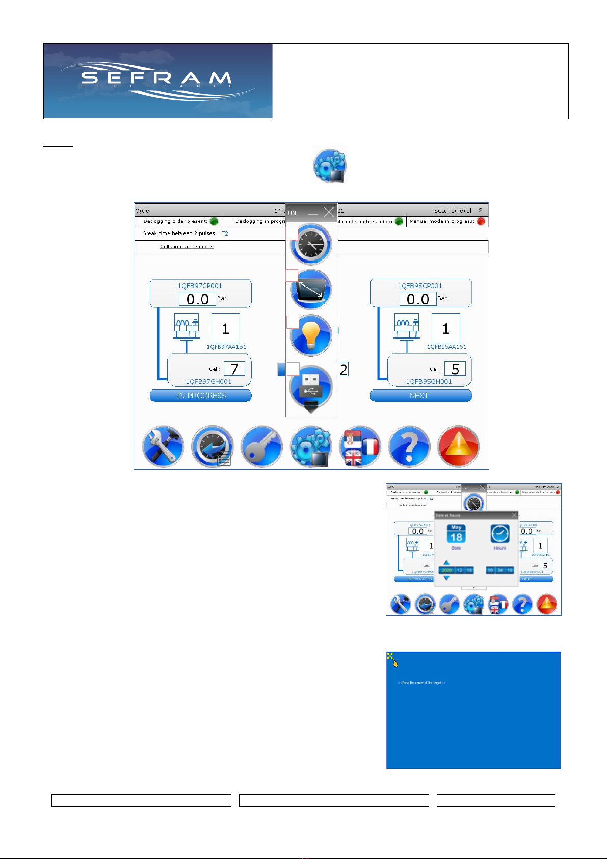
HMI :
Access to the HMI settings is made by pressing the icon
1. Access to the date and time setting by pressing the icon
2. Access to the recalibration of the HMI touch screen by pressing the icon
•Press the cross that appears on the screen
Many times
1
2
3
4
SEQUENCER WITH
DIFFERENTIAL PRESSURE
SWITCH
Technical notice
FI 72.0567.0221E
Page 15 / 45
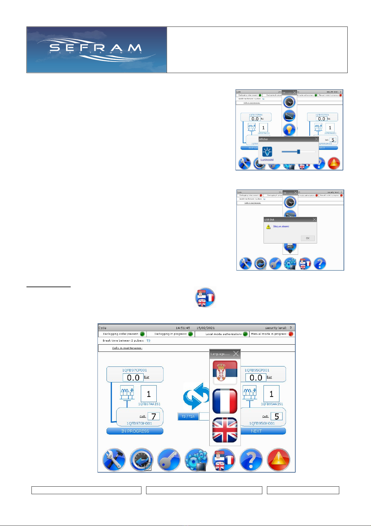
3. Access to the HMI brightness adjustment by pressing the icon
4. Safe removal of the USB key by pressing the icon
Languages :
Access to the language setting is made by pressing the icon
3 languages are available: Serbian, English and French
Press the icon representing the desired language
SEQUENCER WITH
DIFFERENTIAL PRESSURE
SWITCH
Technical notice
FI 72.0567.0221E
Page 16 / 45
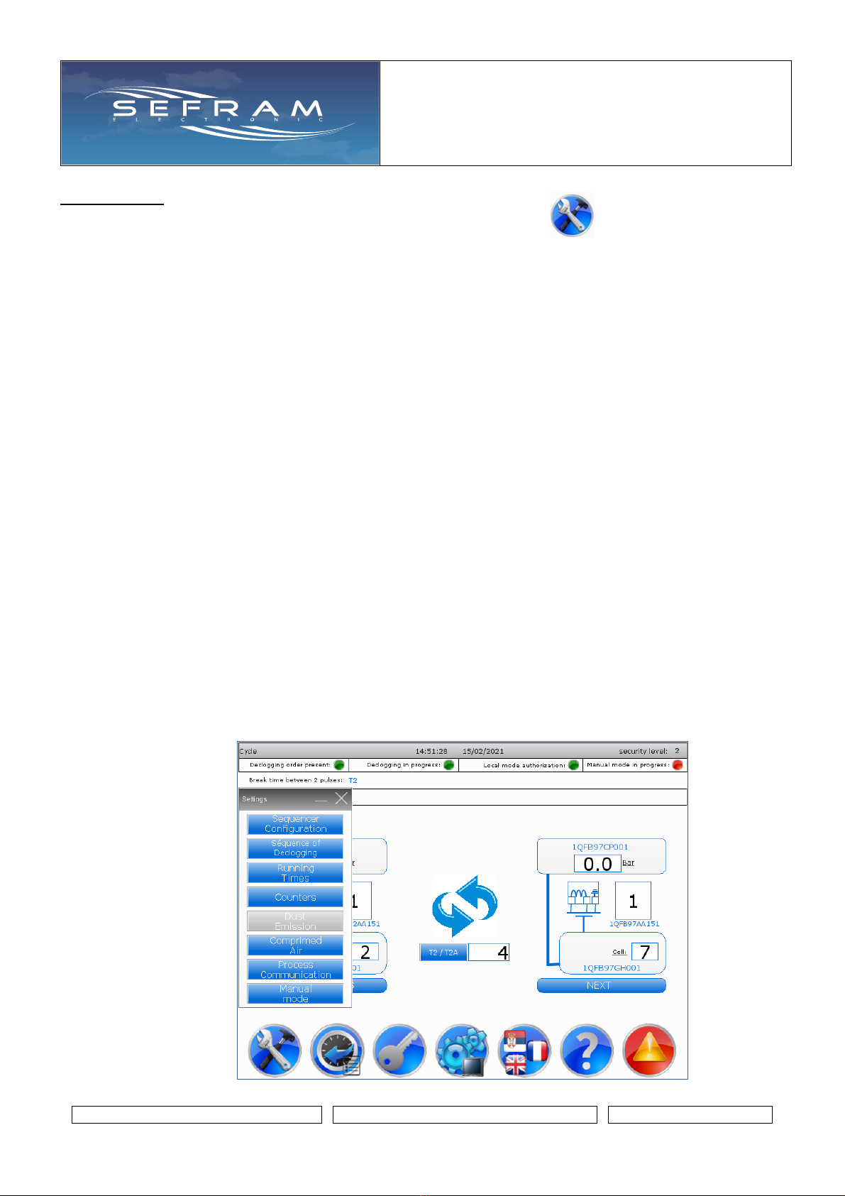
Parameters :
Access to the various sequencer parameters is made by pressing the icon
The parameters are classified according to their function:
•Filter configuration
Display of the number of cells, tanks, number of solenoid valves, etc. which compose the filter
Designation of the declogging cells, tanks and solenoid valves
•Séquence de shots
Configuration of the declogging order for an ONLINE type declogging cycle
•Operating Time
Configuration of operating times, control, etc.
•Counters
Display of various operating counters
•Dust emissions
Settings related to the dust emission incident function - check of pierced sleeves
Accessible if the dust emission function has been integrated into the filter configuration
•Compressed air
Settings related to pressure controls in compressed air tanks
•Customer communication
Settings related to customer communication. Exchange between the sequencer and the operator's
DCS
•Manual mode
Access to the forced operation request of certain functions
Access in level "1: Maintenance"

SEQUENCER WITH
DIFFERENTIAL PRESSURE
SWITCH
Technical notice
FI 72.0567.0221E
Page 17 / 45
Sequencer / filter configuration (1/4):
Display of general parameters on the filter configuration
1. Type of declogging: ONLINE or OFFLINE
2. Number of cells constituting the filter
3. Number of declogging solenoid valves per cell
4. Number of slave boxes required to manage the declogging sequence
5. Number of compressed air tanks constituting the filter
6. Total number of declogging solenoid valves constituting the filter
7. With or without dust emission check option
This option consists in checking that there is no appearance of dust emission downstream of the
filter.
8. If the dust emission check option is integrated, display of the number of probes fitted on the filter.
Parameters 1 to 8 cannot be modified, they are defined during the project.
9. Setting the type of stop of the cleaning cycle
When the SFX+V2 loses the run orders, the cleaning cycle has 2 stop modes:
•Stop "on cycle": the SFX+V2 stops the declogging cycle as soon as the run order is lost.
The cycle will resume where it was stopped when the run order is present again.
•Stop "end of the cycle": the SFX+V2 finishes the current cycle and stops.
Access in maintenance level
10. Depends the configuration, forcing the run order from the HMI
Access at manufacturer level
11. Depends the configuration, forcing the local mode authorisation from the HMI
Access at manufacturer level
1
2
3
4
5
6
7
8
10
11
9

SEQUENCER WITH
DIFFERENTIAL PRESSURE
SWITCH
Technical notice
FI 72.0567.0221E
Page 18 / 45
Sequencer / filter configuration (2/4) :
From this page, it is possible to name each of the tanks constituting the filter.
These names then appear in the CYCLE page, page where it is possible to view the progress of the
declogging cycle.
Naming only possible at manufacturer level.
Operations to do:
•Click in zone “1” the tank you want to name
•Display of the tank selected in zone "2"
•Click in zone 3 so that the
alphanumeric keypad appears
•Enter the desired name on the keypad
•Confirm with the ENT key
•Update of the name of the tank selected in
zone 1
1
2
3
SEQUENCER WITH
DIFFERENTIAL PRESSURE
SWITCH
Technical notice
FI 72.0567.0221E
Page 19 / 45
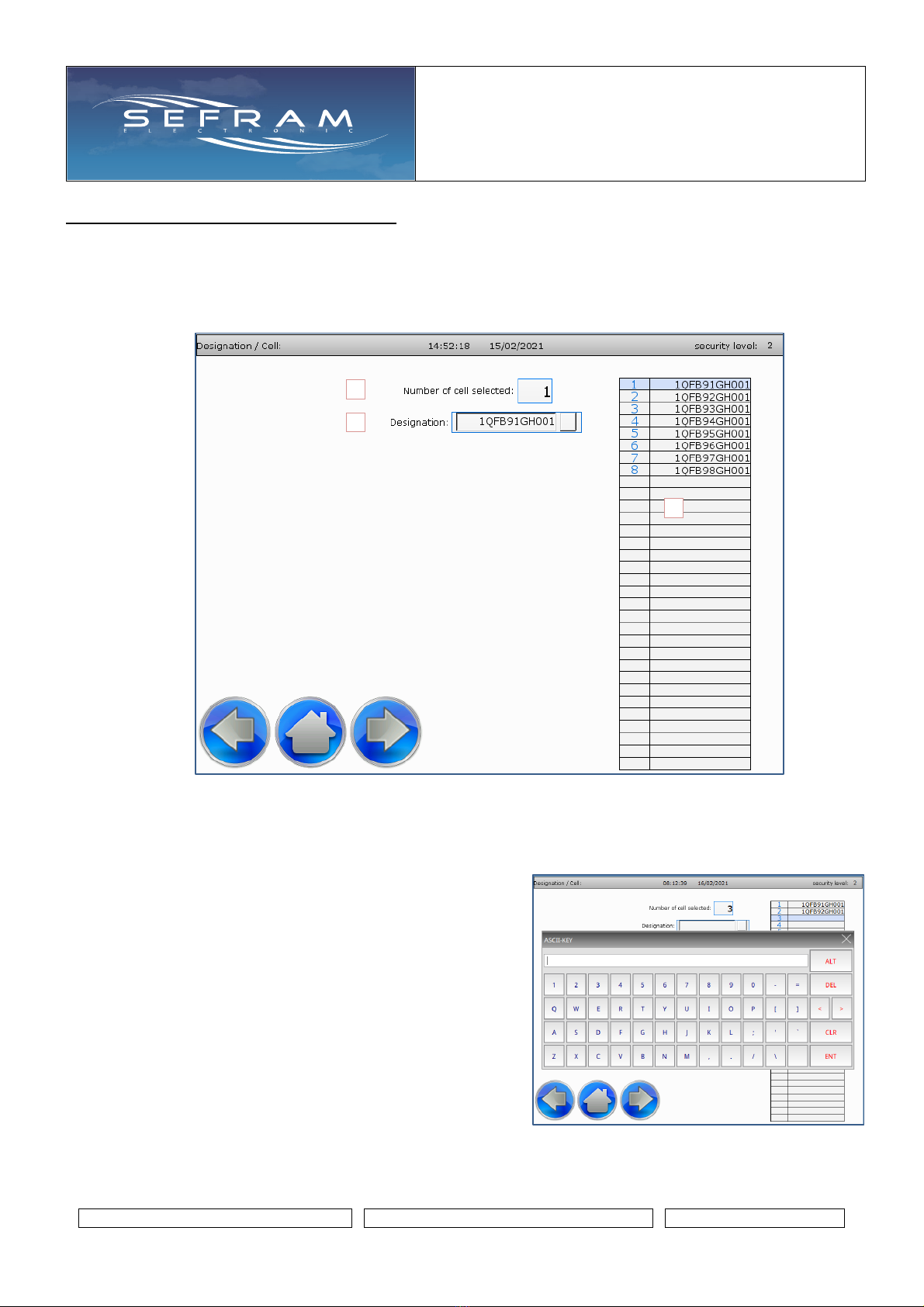
Sequencer / filter configuration (3/4) :
From this page, it is possible to name each of the cell constituting the filter.
These names then appear in the CYCLE page, page where it is possible to view the progress of the
declogging cycle.
Naming only possible at manufacturer level.
Operations to do:
•Click in zone “1” the cell you want to name
•Display of the cell selected in zone "2"
•Click in zone 3 so that
the alphanumeric keypad appears
•Enter the desired name on the keypad
•Confirm with the ENT key
•Update of the name of the cell selected in
zone 1
1
2
3

SEQUENCER WITH
DIFFERENTIAL PRESSURE
SWITCH
Technical notice
FI 72.0567.0221E
Page 20 / 45
Sequencer / filter configuration (4/4) :
From this page, it is possible to name the solenoid valves constituting the filter.
For this part, it is considered that the name of a solenoid valve consists of:
•A prefix identical to all solenoid valves of the same cell
•Followed by a solenoid valve number. Number incremented by 1 for the next one
It is therefore just necessary to record the name of the 1st solenoid valves of each cell.
The following solenoid valves are renamed automatically.
For all other names, it will be necessary to provide it during the project study.
These names then appear in the CYCLE page, page where it is possible to view the progress of the
declogging cycle.
Naming only possible at manufacturer level.
1
2
3
4
5
Table of contents
Other SEFRAM Recording Equipment manuals

Popular Recording Equipment manuals by other brands

Druck
Druck RTD-INTERFACE Quick Start and Safety Manual

Double Intelligence Technology
Double Intelligence Technology SIENNA Multimedia Interface installation guide

Aiwa
Aiwa XC-RW500 Service manual

Tubbutec
Tubbutec SH-1oh1 user manual

Tascam
Tascam DR-680 owner's manual

oticon
oticon Genie 2 Instructions for use


