Sehan Electools SCOUT II User manual
2010. 01. 15 2nd addition /Measuring mode added
2010.01.27 rev /I/O Pin configuration correction
2010.02.05 additional parameter 33,34,35,36
2010.03.26 page 21_ Added 7.8 Connecting to Hybrid HDC controller
2010.04.07 page 31-33_ Added 11.1-3 Protocol, data saving and monitoring
2010.04.15 page 30 _ Cable USB-RS232 code no. corrected
2010.05.11 page 23,24 pin 20 spare1 --> Mid-count signal correction
SCREW COUNTER MANUAL
SCOUT II

- 1 -
INDEX
Contents Page
1. Specification Main features 3
2. Main features 3
3. LAY OUT 4
4. Caution 5
5. Accessaries 6
6. Operation 7
6.1 Mode 7
6.2 Work mode 8
6.3 Log-in mode 8
6.4 Parameter mode 9
6.5 Measuring mode 10
6.6 Program ¶meters 11
6.7 Parameters 12
7. Interface 14
7.1 25P I/O interface 14
7.2 Input (Negative common wiring )15
7.3 Input (Positive common wiring )16
7.4 Output (Positive common wiring )17
7.5 Output (Negaitivecommonwiring)18
7.6 I/O Wiring example #1 - tower lamp, sol valve 19
7.7 I/O Wiring example #2 - Inter-Lock of two driver 20
7.8 Connecting to Hybrid HDC controller 21
8. Timing chart 23
9. Timing chart details for OK /NG setup 24
9.1 Fastening OK 24

- 2 -
Contents Page
9.2 Fastening NG (Time Lapse )24
9.3 Fastening NG (Time Over )25
9.4 Fastening NG (No Torqeu Up )25
10. Cycle Start /Stop in the various operating condition 26
10.1 Auto start 26
10.2 Start (Continuous ON )26
10.3 Start (pulse) +Stop by time limit (Optional) 27
10.4 Start (pulse) +Stop (pulse) 29
11. RS-232C &USB COM port 30
11.1 Protocol details 31
11.2 Parameter change and save 32
11.3 Monitoring data output 33
12. PC software, SCOUT II Manager 34
12.1 Software install 34
12.2 How to use 34

- 3 -
1. Specification
No Description Specification
1Input power 1. 30~40VDC from KT-38D(FT-40D)
2. External power of 24VDC, 1A
for Hybrid controller
2Available tools KT-38D, FT-40D, HDC-30i, HDC-40i
3No of Program 8programs
4Count number 99 for each program
5Screwdriver port 4ports for KT-38D(FT-40D)
1port for HDC-30i, HDC-40i
6Com port RS232C, USB(B)
7I/O Input 15, Output 7
8PC software Scout Manager (on Windows)
9Parameter setting on front panel or PC software
10 Program share
Maximum 4screwdrivers (with KT-38D v4.3 or FT-40D)
can share one program
※Only one(1) KT-38D with the version lower than v4.3
can be connected to Scout II.
2. Main features of SCOUT II
-Maximum 5screwdrivers can share one program of Scout
(4of KT-38D v4.3 or FT-40D through A,B,C,D port +1extra one through 25P I/O )
-OK /NG judgment for each fastening
-Display of the remained screw number to be fastened
-Variable signal type of the cycle start and stop
-Error display with beep sound
-Display of the fastening error information
-Built in Fastening time measurement function
-No extra power is required for KT-38D, FT-40D
-External power (24VDC) is required for HDC or other tools through 25P I/O

- 4 -
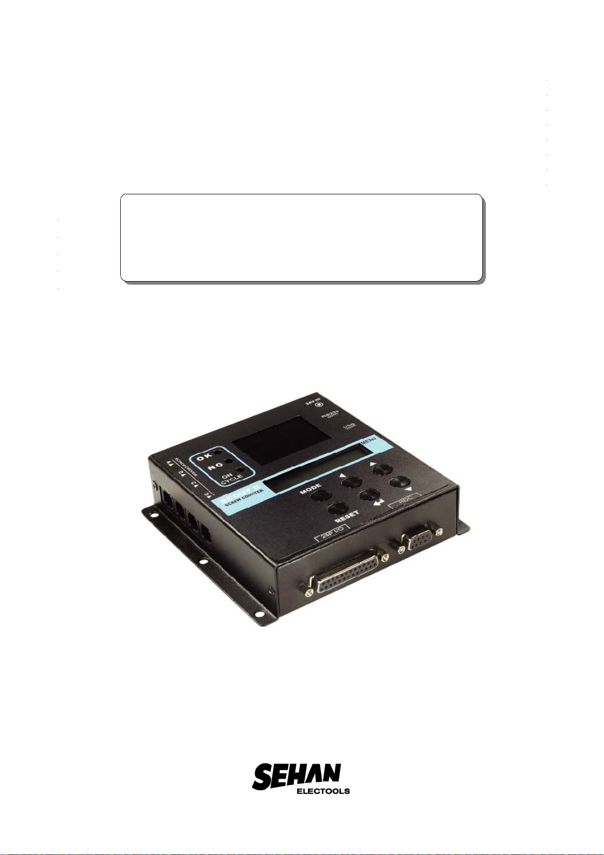
3. LAY OUT
25P I/O port Hybrid screwdriver port
Numeric LED for the number of fastening screw
Power Input
24VDC,1A
for HDC controller
Menu LCD
Key
Fastening result by NG /OK
RS232C Com port
USB
Com port
A
B
C
D
126.5 mm
dia. 5mm
33 mm
136.5 mm
RJ-11(6P) Screwdriver port
KT-38D, FT-40D
55.5 mm55.5 mm

- 5 -
1) The power is supplied from KT-38D or FT-40D controller to Scout through RJ-11 "A"
screwdriver port. The screwdriver port "A" works for power feeding from the
connected controller KT-38D or FT-40D additionally.
If the screwdriver port "A" is empty (not used), then external power (24VDC, 1A) is
required.
2) Scout II have 4screwdriver port for direct connecting of KT-38D and FT-40D.
Also one extra screwdriver can be connected through 25P I/O.
3) Cycle can be started by the signal from PLC, sensor or other equipment.
Also Scout gives the cycle complete signal to PLC or other equipment, too through
the 25P I/O port
4) The numeric LED shows the number of screws which should be fastened for acycle.
5) Power Input (24VDC,1A) is required when the Hybrid screwdriver is connected.
Don't connect both KT-38D (or FT-40D) and HDC controller together to Scout II.
6) Fastening results are displayed by NG or OK for every fastening. In order to use
NG/OK judgment, the different parameter setting can be saved on the program no.
from 1to 8.
7) Parameter setting is also possible on Scout Manager (pc software). It transmit
the settings to Scout II. The settings on programs can be saved in csv format file.
4. Caution
1) The screw counter SCOUT II should be used with KT-38D or FT-40D controller only.
Never use the screw counter with any other tools not specified by the manufacturer.
It can be dangerous by the electrical shock.
2) Be careful of right connecting cable between the screwdriver controller and Scout II.
3) Never use non specified cable by the manufacturer.
4) Don't connect both KT-38D (or FT-40D) and HDC controller together to Scout II.
5) Do not use the screw counter near fire and magnetic environment.

- 6 -
5. Accessaries (Option items )
2M
Connection Cable
RJ-45(8pin)-RJ11(6pin)
Scout -KT-38D(FT-40D)
(7000007)
USB cable[A-B] type 1.8M
(part no. PELZ943)
AC adapter(SMPS) model:PAG024M
24VDC,1A (part no. GCM6913)
RS232 cable /USB_A type
1.8M (part no. PELZ939)
FT-40D
KT-38D
25P I/O cable (M-M) 1.8M
(part no. PELZ944)
PLC
HDC Hybrid
controller

- 7 -
6. Operation
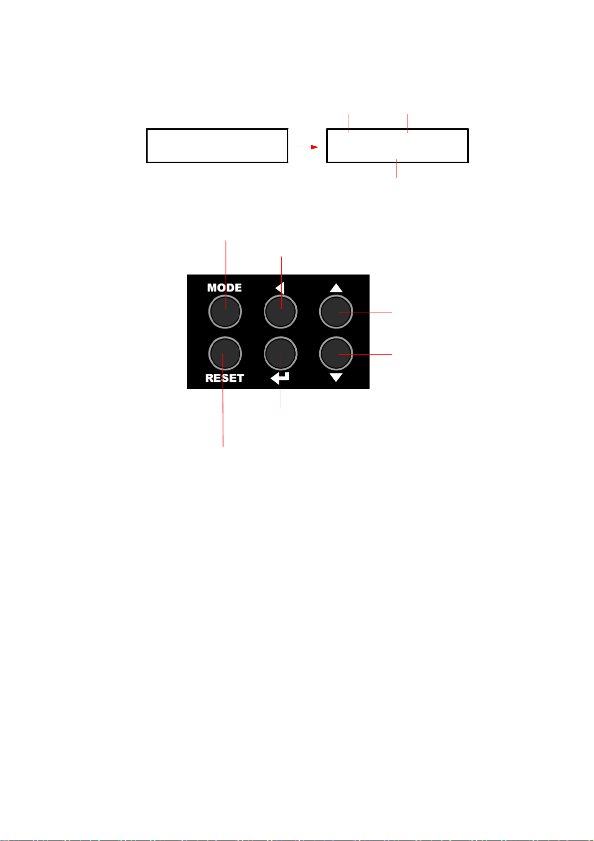
6.1 Mode
By pressing the MODE button, it circulate Work,
Log-in, Parameter and Measuring mode.
Work means operating.
Before parameter mode, password is required.
Every settings is possible in Parameter mode.
Once logged in, it circulate Work, Parameter
and Measuring mode, until the power is off
and on again. Fastening time is monitored on Measuring mode. Minimum and
Maximum measured time can be saved on the selected program #.
Factory setting password :"0"
Measuring Parameter
Work
(Log-in)
1WORK 【READY 】
<0000000 > 0000mS
[PARAMETER ]
PLEASE ENTER
[07] CNT NUMBER 7
[05]
[07] CNT NUMBER 7
[05]
RESET
RESET
MODE
MODE
[PASSWORD ]
[ 0000 ]
[PASSWORD ]
[LOGIN ]
Password
MODE
log in
untill re-boot
[MEASURING] [00]
[0000ms] [0000ms]
[MEASURING] [00]
[0000] [AVG:0000]
[MEASURING] [02]
[PROGRAM NO: 5]
RESET
MODE
MODE ▲
▼

- 8 -
6.2 Work mode
6.3 Log-in mode
1WORK 【READY 】
<0000000 > 0000mS
Program #1to 8
Judgement (READY /OK /NG )
Total fastened screw number
Fastenting time
Mode
Program #UP (1 to 8)
Program #DOWN
Error and Cycle RESET
Move to next MODE when only cycle reset
Number UP (0 to 9)
Number DOWN
Log-in enter
Move the cursor left
1. Move back to work MODE without password login
2. Move to next Parameter MODE after password login
[PASSWORD ]
[0000] [PASSWORD ]
[LOGIN ]
Factory setting password "0000" can be changed in P33 parameter.
Decrease count number (-1)
- 9 -
6.4 Parameter mode
[PARAMETER ]
PLEASE ENTER [01] CNT NUMBER 1
[05]
Parameter #Description
setting data
Number UP
(Parameter #, data)
Number DOWN
Select Parameter #&Save data
Move the cursor left
Move to next Work MODE on Mode display
Move back without saving data

- 10 -
6.5 Measuring mode
[MEASURING] [00]
[0000ms][0000ms][MEASURING] [02]
[PROGRAM NO: 1]
Total measured data Description
Program #to be linked and
saved with the current
Min/Max data
Number UP
(Parameter #, data)
Number DOWN
1. Move the cursor left
2. Cancel the last data in calculation
Move to next Work MODE on Mode display
[MEASURING] [00]
[0000] [AVG:0000]
Min time Max time
last data Average value
Display
select
▲
▼
▲
▼
Link and save the current data to the
selected Program #
Move back without saving data

- 11 -
6.6 Program #and parameters
The program numbers from 1to 8are effected together with parameter 1~8 for
number of screws, P9~16 for minimum tightening time, P17~24 for maximum
tightening time.
Program #Number of
fastening Min. time Max. time
1P1P9P17
2P2P10 P18
3P3P11 P19
4P4P12 P20
5P5P13 P21
6P6P14 P22
7P7P15 P23
8P8P16 P24
1st data 2nd data 3rd data

- 12 -
6.7 Parameters
P# Name Specification Default
P01-
P08 Program #Save total number of screws on P1-8. 1
P09-
P16 Minimum tightening
time Minimum screw tightening time
Input : 0.000 - 9.999 sec ("0":No use )0
P17-
P24 Maximum tightening
time Maximum screw tightening time
Input : 0.000 - 9.999 sec ("0":No use )0
P25 Type of cycle start
and stop
Select one of 4types of Cycle Start signal
input
0:Auto
1:Start (continuous ON)
2:Start (pulse ON) +Stop (timer on P27)
3:Start (pulse ON) +Stop (pulse ON)
0
P26 Input signal type
Select one of 2signal type
0:Active High ( 0 --> 1 )
1:Active Low ( 1 --> 0 )
※When Active Low is selected, the only
one(1) screwdriver ("A") can be connected.
0
P27 Timer setting for
Cycle start/stop type
2of P25
Input screw tightening time limit after Cycle
start signal
Input :0.0-9.9sec ("0":No use )0
P28 Minimum time to
judgement
Set the minimum time to judgement of
OK/NG
Input :0-99(x0.1s) ("0":No use )0
P29 Com port select Select one of two com ports.
0:USB
1:RS-232C 0
P30 Hybrid HDC connect Select one of two condition
0:Not Connected (not use)
1:Connected (used) 0

- 13 -
P# Name Specification Default
P31 Fastening buzzer
Select one of followings
0:Not use
1:OK only
2:NG only
3:OK +NG
0
P32 Cycle buzzer
Select one of followings
0:Not use
1:OK only
2:NG only
3:OK +NG
0
P33 Reset key control Select Reset key Enable /Disable
0:Disable 1:Enable 0
P34 Program key control Select Program key Enable /Disable
0:Disable 1:Enable 0
P35 Program Select Input
with Binary code
Program Select Input by Binary code with
Pin no. 1~3
0:Disable 1:Enable 0
P36 Monitoring data
output setting
Select Enable /Disable of monitoring data
output through RS-232C port
0:Disable 1:Enable 0
P37 Mid-Count signal
setting
Count complete signal come out after the set
number of Mid-Count signal during the cycle
0:
No use
1~99 : Count number
0
P38 Password
Key in the password in 4numbers.
Initial factory setting password is "0000"
If the password is forgot, click the "PInit "
menu on Scout manager control bar with
password "77", then all parameters
are changed to the factory setting.
Once again, the factory setting password is
"0000"
P39 Parameter initial All parameter are initialized to the factory
setting. Key in "77" on P34 and press
Enter button.
P40 Version information It is not allowed to change. 052

- 14 -
7. Interface
7.1 25P I/O interface details
The configuration of 25P I/O port for remote control is as below
PIN no. Configuration IN /OUT
1External Motor Run signal
INPUT
(to Controller)
2External Torque Up signal
3Cycle Start
4Cycle Stop
5Cycle Reset
6Driver Lock
7Spare 1
8PS1 (Program selecting) PS1(P35 Enable)
9PS2 (Program selecting) PS2(P35 Enable)
10 PS3 (Program selecting) PS3(P35 Enable)
11 PS4 (Program selecting) spare
12 PS5 (Program selecting) spare
13 PS6 (Program selecting) spare
14 PS7 (Program selecting) spare
15 PS8 (Program selecting) spare
16 Cycle complete OK
OUTPUT
(from controller)
24VDC, 50mA
max
17 Cycle complete NG
18 Tightening OK
19 Tightening NG
20 Mid-count complete signal
21 Driver Lock
22 Spare 2
23 No use
24 Input COM
25 Output COM
1
13
1425
- 15 -
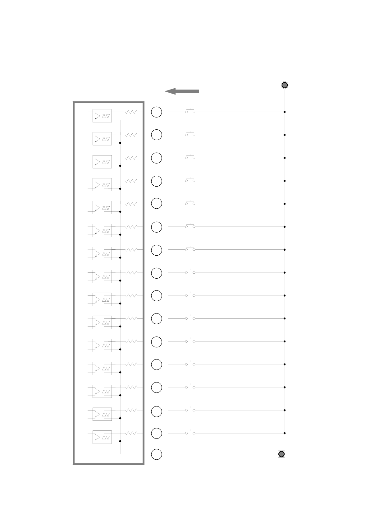
7.2 INPUT (Negative(-) Common wiring)
7
6
5
4
3
2
1
SCOUT II
External power (24VDC+)
Input COM
8
9
10
11
12
13
14
15
24
Cycle Start
Spare 1
PS1
PS2
PS3
PS4
PS5
PS6
PS7
PS8
Cycle Stop
Cycle reset
External torque up
External motor RUN
Driver Lock
Return 24V(-)
- 16 -
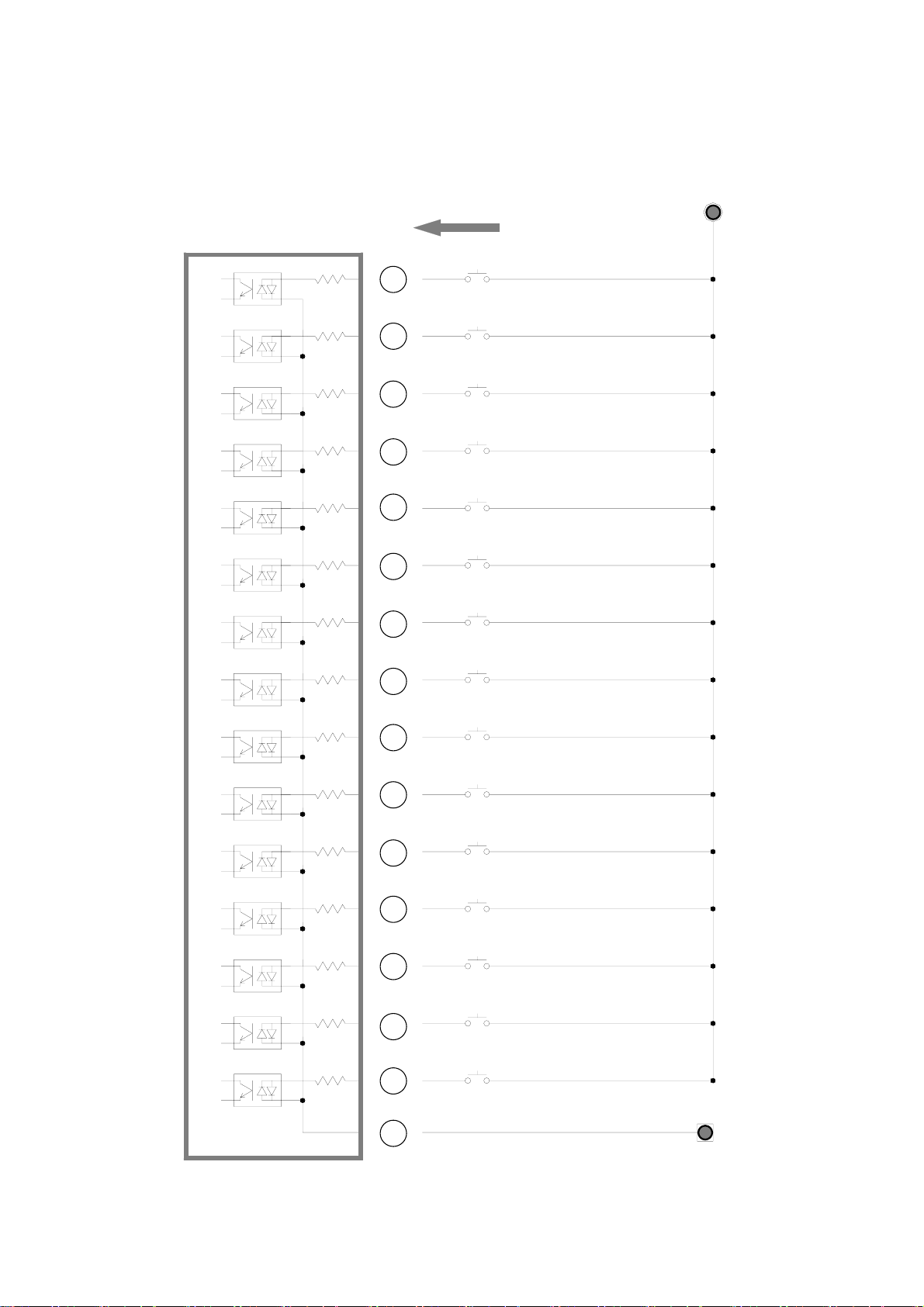
7.4 INPUT (Positive(+) Common wiring)
7
6
5
4
3
2
1
SCOUT II
External power (24VDC+)
Input COM
8
9
10
11
12
13
14
15
24
Return 24V(-)
Cycle Start
Spare 1
PS1
PS2
PS3
PS4
PS5
PS6
PS7
PS8
Cycle Stop
Cycle reset
External torque up
External motor RUN
Driver Lock

- 17 -
7.4 OUTPUT (Negative(-) Common wiring)
Cycle complete OK
Mid-count complete
No use
Driver Lock
24VDC, 100mA max
21
22
23
16
Return(24V-)
External power (24V+)
Output COM
SCOUT II
25
Tightening OK
Spare 2
17
18
19
20
Cycle complete NG
Tightening NG

- 18 -
7.5 OUTPUT (Positive(+) Common wiring)
Cycle complete OK
Mid-count complete
No use
Driver Lock
24VDC, 100mA max
21
22
23
16
Return(24V-)
External power (24VDC+)
Output COM
SCOUT II
25
Tightening OK
Spare 2
17
18
19
20
Cycle complete NG
Tightening NG
- 19 -
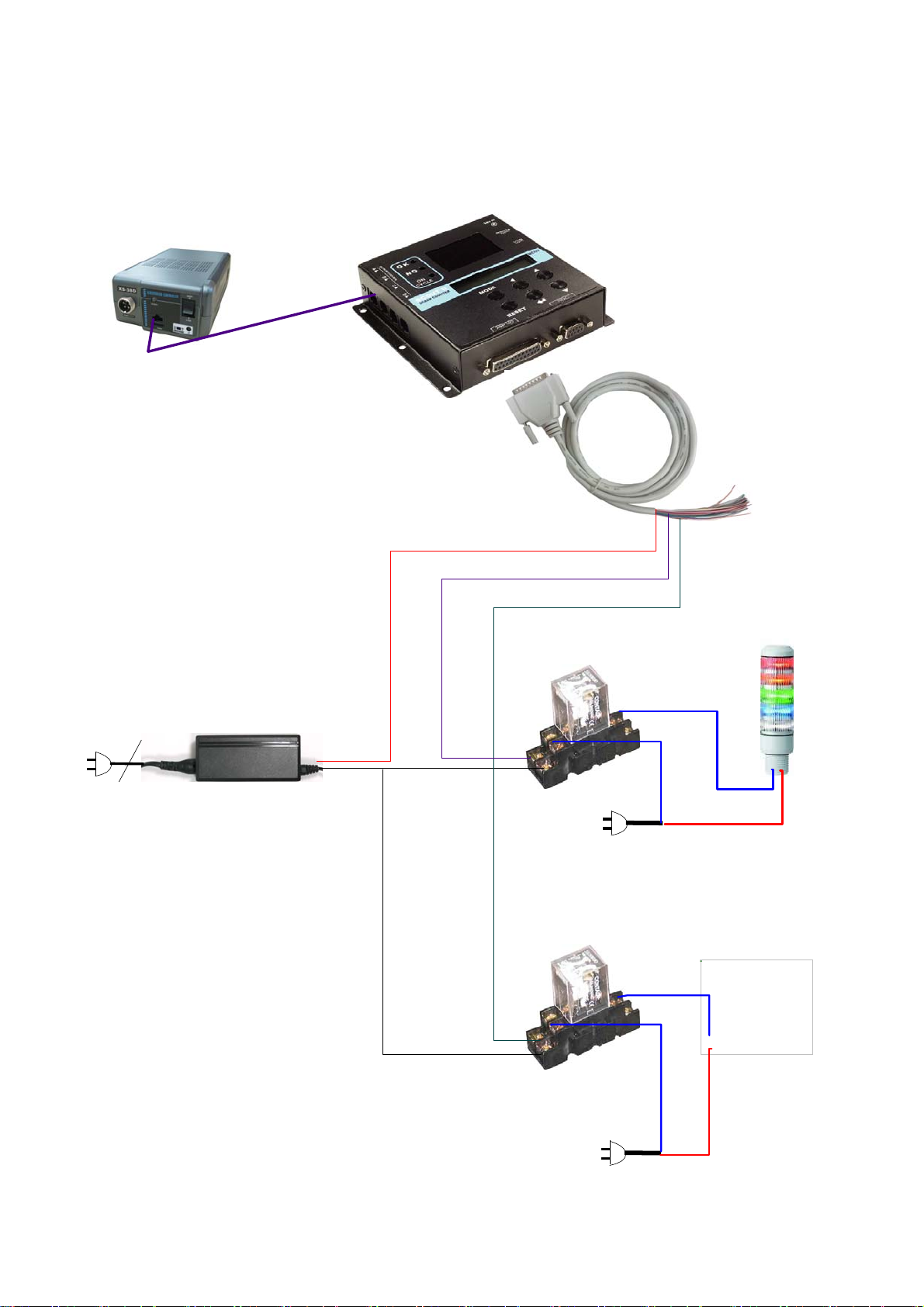
7.6 Wiring example #1 - Tower lamp, solenoid valve, sensors, switch
D:₩sehan1₩해외업체₩DOGA₩Position controller₩sol valve.jpg
AC220V
Solenoid valve
AC220V
Tower lamp
NG
DC12~24V Adapter
Pin 25 Output com
+Positive
-Negative
Pin 17 Cycle complete NG
Pin 16 Cycle complete OK
DC12~24V Relay
DC12~24V Relay
COM
N.O
COM
N.O
Table of contents


